Bob McAuliffe
Active Member
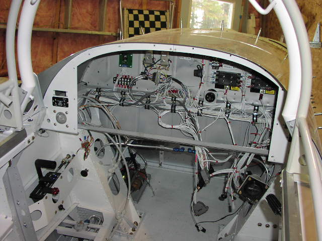
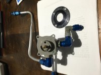
I am installing the Andair Fuel Valve in my RV8 and see that the Andair Valve is too large for Van's Fuel Selector Bracket. How did other folks install their Andairs?
Bob McAuliffe
Bob McAuliffe


Saville
I plan on copying your method. I’d like to know which calculator you used on the engineering website. I tried the calculator but I want to be sure I am using the correct one. When I crunched the numbers they did not turn out verbatim to yours. I feel the error is definitely on my part. The reason I ask, I wanted to see what it was for .040 material instead of the .064
Next time I take mine off I'm putting on some nutplates. It seems surprising, but getting access to that area is not easy once you have the seat in. My advice is to use nutplates as Saville shows.Saville
I plan on copying your method. I’d like to know which calculator you used on the engineering website. I tried the calculator but I want to be sure I am using the correct one. When I crunched the numbers they did not turn out verbatim to yours. I feel the error is definitely on my part. The reason I ask, I wanted to see what it was for .040 material instead of the .064
Next time I take mine off I'm putting on some nutplates. It seems surprising, but getting access to that area is not easy once you have the seat in. My advice is to use nutplates as Saville shows.
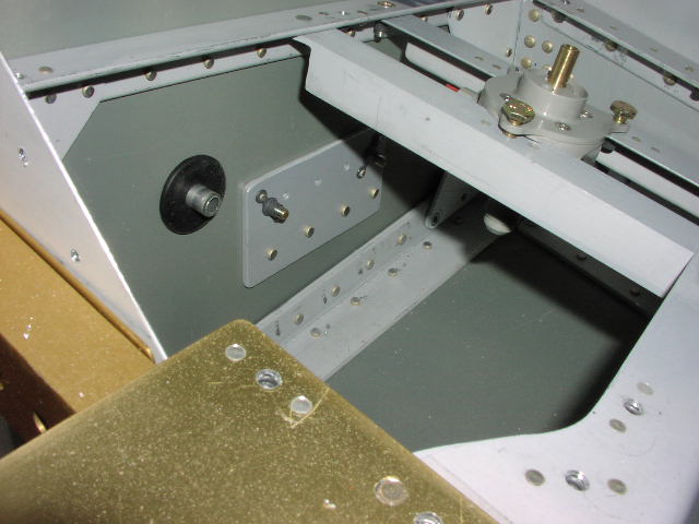
This is how I did it.
https://vansairforce.net/community/showthread.php?t=179791&page=3
My goals in this design were six-fold:
1) Replace the LEFT-BOTH-RIGHT-OFF selector with LEFT-RIGHT-OFF
2) Get rid of all cross braces so that I could get maximum access to the fittings on the selector should I need to.
3) Eliminate the need to get a wrench UNDER the cover plate in order to gain access to the selector and the fittings/fuel lines.
4) Make the connect/disconnect to the left tank much easier than it was with the old installation.
5) Move the selector aft and inboard to make access easier and also make the run of the fuel lines easier.
6) eliminate the multiple connectors on the line that leads from the selector to the aux pump/engine.
So I ran an analysis with various thicknesses of cover plate to find a thickness that would not flex under a +6G load
See Post #17
Post #23 shows a drawing of what I did.
Post #26 shows the installation with a plexiglass cover plate - this was a test install.
Now if I had it to do all over again, I might eliminate the small underplate and just use the nutplates I attached to the selector to mount it directly to the cover plate.
I'm very happy with the installation.
Thank you for posting details!
Can I ask the reason for not wanting the "Both" option on the fuel valve?
Sure.
Prior to starting that project, I had read several posters saying that for high wing aircraft, L-B-R-O is find as the fuel lines are gravity fed and therefore always full between the tanks and the selector. But that for low wing aircraft - where the tank feeds are often below the selector, it's better to not have BOTH because at BOTH, one line will suck air if you run the tank dry.
One FAA inspector on VAF (in some other thread) said he would fail the inspection and not deem the a/c flight-worthy with a L-B-R-O selector on a low wing.
I'm sure there are numerous opinions on this.
But since I had to replace the selector to begin with (it was poorly installed and some of the mounting holes expanded - see attached thumbnail of the old selector: lower right mounting hole), I figured I'd save myself and a future owner any hassle and go L-R-O.
Cheers.
Well let's see. I just re-ran it.
Firstly I selected FIXED EDGE RECTANGULAR PLATE - CONCENTRATED LOAD
Then I changed all the units to inches and "psi" for the load
BUT.....the units for max deflection was micrometers. That's to get SOME numeric result other than zero.
...and I got a max deflection of 0.0 for a load of 3.018
Then for the second run of a load of 80, I got the same 0.0008
So check your units and see if they are the same as mine in post #17
Also, as I wrote above, the whole thing would have been simpler had I attached the selector directly to the cover plate. The way I did it, if you just wanted to remove the cover plate you have to remove all the edge screws plus the 4 that connect the underplate to the cover plate.
This removes the need to remove the selector switch handle - something I'd like to minimize.
If you wanted both plates removed then you remove all the edge screws of the cover plate, the 3 screws for the selector, and the switch handle itself. Kind of a wash.
Pays your money and takes your choice.