What's new
Van's Air Force

Don't miss anything! Register now for full access to the definitive RV support community.

Cowl Differential Pressures

DanH

Legacy Member
Mentor
Let's explore a thought. Why do some RV's cool better than others?

Set the obvious stuff aside and consider the basics. Air flows down through the cylinder baffles for one reason; the air pressure in the upper cowl is higher than the pressure in the lower cowl. If differential pressure is high, you get lots of air through the baffled cylinder fins. If the pressures are the same (zero differential pressure), no air moves through the fins. The majority of aircraft are somewhere in between.

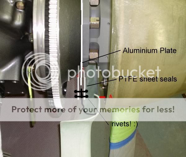
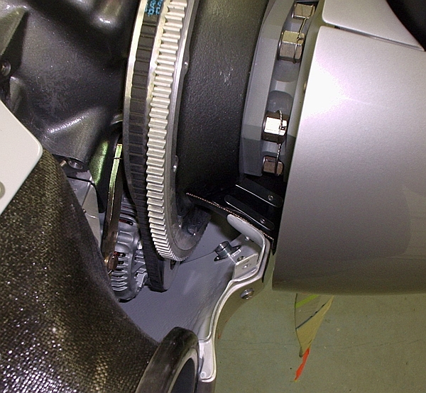
I'm installing a cowl right now and got looking at the gap in the propshaft area:

Cowl%20Propshaft%20Air%20Leak.jpg


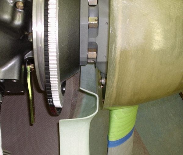
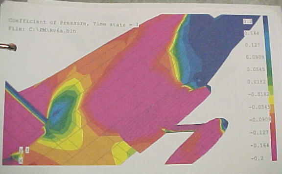
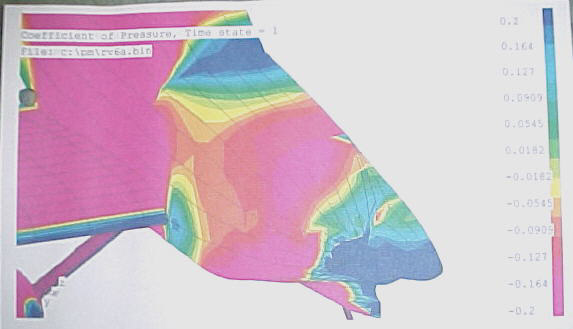
Anybody have a CFD plot of local pressures around the nose of a Vans cowl? You know, the graphical plot with different colors for different pressures? (Dr Svingen called it CFD "porn" in another thread, which made me laugh.) As I recall, pressure around the base of the spinner is pretty high.

If so, I suspect the huge leak path provided behind the spinner signficantly reduces differential pressure (and thus cooling) by raising pressure in the lower cowl area. How huge is it? If the spinner-to-cowl clearance is 3/8", the area of the gap between the spinner and the cowl is 15 square inches (13"D x pi x .375"). That's more area than a 4" diameter round cooling plenum inlet (12.5 sq in).

Spinner-to-cowl clearance is highly variable between builders. A cowl fitted with a bare minimum of spinner clearance would have better differential pressure. With an 1/8" gap, area is down to 5 sq inches.

Maybe we should be thinking about how to seal the propshaft area....and there may be some data points available.

First, surely with 8000 RVs flying I'm not the first guy to think of this. Anybody with a report?

Second, I seem to recall Grumman owners talking about sealing in the propshaft area.

Three, I did an RV8 cowl for a friend with a large diameter Mooney spinner. That spinner mounted on the common bell-shaped backplate bolted to the ring gear carrier rather than the "bolt to the prop hub" backplate supplied by Vans. That required modification to the cowl nose behind the spinner. Bell-to-cowl clearance was kept to a minimum, and I recall CHT and oil temps to be excellent.

Last, if someone is willing to do a little flight test experiment......
 
Last edited:
The Grumman...

....
Second, I seem to recall Grumman owners talking about sealing in the propshaft area.

..........

..non-STC "fix" is a piece of 1 inch wide and fairly thick sponge rubber on the front face of the cowl just behind the spinner.

Have it touch the spinner, and at the first engine start it will wear itself in...:)

As with most cooling mods... some swear by it, and others say it had no effect when they installed it.

The Grummans are a bit different in the front baffling since they have a large vertical "dam" that is sealed agaist the front of the cowling with baffle material.

Front baffle pic (upside down in pic)

http://www.aucountry.com/ACA_Folder/ACA_Services/Projects/Baffles/B13.html

There is no tight fitting connection to the cowl intake holes.
 
I have some CFD plots for a 6A and it is high pressure at the spinner/ cowl junction for the most part. There is high airflow here as this is where my OAT thermistor is placed (beside prop flange) and my 3/8 slot cools the PSRU really well. For low drag and better cooling on air cooled engines, you'd want this as tight as possible or even sealed somehow.

I'm reading Hoerner's book right now and there is some fascinating info on cooling drag, both for air and liquid cooled engines.
 
Last edited:
Cooling

Hi Dan,
I have IO 360 angle valve installed on my 8. I read about all the cooling horrors from everyone else. I was very meticulous fitting my baffles, (baffles 3/8 inch from cowl with rubber material sealing the rest). I did not want to silicone my baffling to the engine until I flew a few times to check everything out before making it so permanent. After 75 hours which included full power climbs to 10,000 ft., the highest oil temp I've seen was 210 degrees on the full power climbs and cruise is around 175 degrees. Most of these test were done in mid September with temps around the mid 80's. At present with the cooler temps, I have my oil cooler blocked off completely and only get about 165 degrees at cruise. If I throttle back to fly with my friends with RV 4's, I usually get around 145 degrees oil temp. As of now I don't plan on putting the silicone around the baffle to engine gaps. I'll wait till next summer to see if it's required. Guess what I'm getting at is if you keep the baffling neat and tight, you probably won't have a cooling issue. At least I don't.:)
 
<<The Grummans are a bit different in the front baffling since they have a large vertical "dam" that is sealed agaist the front of the cowling with baffle material.>>

Thanks Gil. The front dam makes the Grumman a poor data point for this question.

<<I have some CFD plots for a 6A and it is high pressure at the spinner/ cowl junction for the most part. >>

Ross, any chance of a scan?

<<I was very meticulous fitting my baffles>>

Bill, I don't doubt that <g> But what spinner-to-cowl clearance did you use?
 
Spinner Back Plate Seals

Dan,
I plan to install a circular brush seal between the cowl and the rotating back plate to reduce the flow.
An example of the brush is shown here:
http://www.precisionbrush.com/brush_seals.asp

I will use an antistatic type brush attached to the cowl making contact with the spinner back plate. I have reservations about the brush life and possible wear on the back plate so I plan to hard coat anodize the surface and limit the wear to the brush.

From your photos I believe I am in the same state of construction as you so I will not be in a position to test the brush life any time soon.
 
Dan
A small gap here is a good idea to reduce airflow, but the direction of airflow at this location is out, rather than in. I have measured the air pressure in my upper and lower plenums relative to the outside air and both are higher. If it were not this way than the air would not flow out the aft opening of the cowling. My upper plenum has between 5 and 6" of water column pressure more than the bottom cowling and the bottom cowling is about 7" more than the outside air. The airflow spilling out this spinner/cowling gap disrupts the flow of air into the engine air intakes and thus reduces the effectiveness of the inlets. That is the only way I can explain the results that I have found on my aircraft.
I blocked off the spinner area using a flat plate and a foam ring around the prop shaft. This reduced my engine cylinder temps by about 20F without lowering the aircraft speed. Often when you increase cooling you can actually slow the airplane down due to increased airflow so I consider this particular modification a good one.
 
Tom,
<<I have measured the air pressure in my upper and lower plenums relative to the outside air and both are higher. If it were not this way than the air would not flow out the aft opening of the cowling. My upper plenum has between 5 and 6" of water column pressure more than the bottom cowling and the bottom cowling is about 7" more than the outside air.>>

Good info! Pressure higher than ambient certainly makes sense in the lower cowl. However, perhaps external pressure in the immediate spinner gap area is also higher than ambient? That's why I was asking for some of that CFD porn.

You got a change in CHT, so the seal does something. Very interesting.
 
Interesting post from Tom. I've oiled, instrumented and tufted my cowling and the air is going in on mine. The OAT probe also proves this too as it is mounted to the prop brush mount about 2 inches aft of the spinner back plate.

My airplane has rads and oil coolers sealed to the stock inlets so this may not be the same as with a Lycoming and I have a lot more exit area with my exit ramps on the sides of the cowling in a low pressure zone.

You'd be interested to know that there is reverse flow just outboard and aft of the stock inlets.

Dan, there is a photo here of the side lower cowling CFD plot: http://groups.yahoo.com/group/subar...ode=tn&order=ordinal&start=1&count=20&dir=asc
 
Last edited:
Cooling flow theoreticals...

Dan, Back in 1994 I was working full-time on an aircraft called the KL-1C, by Kestrel Aircraft (they're gone now). I did all the cooling flow analysis, CFD around the cowl, inlet/exit area sizing, cowling surface loads... pretty much the whole sha-bang. I had 4.25" annular inlets and about 60 in^2 on a fixed belly exit. Very close to the RV's...

All this to say that cooling effectiveness is all about mass flow and pressure differential. Leaks do nothing but reduce your delta-p and require higher mass flow through the system to get the job done. Its no surprise to me that blocking off the gap you pointed out in the first post here had positive results for those who tested it.

ANY leaking air - that's air not flowing through the cooling baffles, but around them in some way - is bad. Look at how the Reno racers manage this to a fanatical level. So, you're on the right track. I have a full spread sheet to analyze cooling flow drag by way of momentum change from inlets to exit. Its based on the compressible Bernoulli equation. To get valid results from the analysis requires some data acquisition, which can be really tricky to accomplish since pressures and temps vary wildy inside the cowl. Where and how you instrument in this area can give wide variations in data with even small changes in transducer location. I remember Van running into this problem back in the early 90's. So just experiment and see what works is the best way for us in the VAF community, IMHO.

************

Finally, I'd like to voice (once more) the idea that we could benefit pretty nicely from adding cowl flaps to these aircraft. Throttling the cooling flow at the exit is the way to do it - not at the inlet. Basically, I'd propose adding a flap on each side of the lower cowl, down low and just ahead of the firewall. Hinges would be vertically oriented, and the flap could be controlled with linear electric actuators, or possibly mechanically. I calculated a potential 5+ mph speed gain for my RV4 with this mod, but then I sold it :(

A belly flap could also work, but might cause undesirable pitch trim issues when raised/lowered.
 
Last edited:
I agree with Bill here. The Sport Class guys at Reno get the spinners really close to reduce the gap.

I had a cowl flap on my 6A at one time and it was worth 4-5 knots closing it up in level flight. You don't need all that mass flow in cruise. Some of the liquid cooled warbirds show around a 20 mph gain by closing the rad flaps.
 
Dan
A small gap here is a good idea to reduce airflow, but the direction of airflow at this location is out, rather than in. I have measured the air pressure in my upper and lower plenums relative to the outside air and both are higher. If it were not this way than the air would not flow out the aft opening of the cowling. My upper plenum has between 5 and 6" of water column pressure more than the bottom cowling and the bottom cowling is about 7" more than the outside air. The airflow spilling out this spinner/cowling gap disrupts the flow of air into the engine air intakes and thus reduces the effectiveness of the inlets. That is the only way I can explain the results that I have found on my aircraft.
I blocked off the spinner area using a flat plate and a foam ring around the prop shaft. This reduced my engine cylinder temps by about 20F without lowering the aircraft speed. Often when you increase cooling you can actually slow the airplane down due to increased airflow so I consider this particular modification a good one.

I agree with Tom.
The flow at the spinner cowl gap is from the lower cowl area towards the outside, not the inside. The bigger the gap, the higher the flow volume. This outflow causes two problems. It disrupts the inflow in to the cooling air inlets and induces already heated air into the engine cooling path.
The airflow may act differently with other power plant installations but on an RV this seems to be the case with a Lycoming and the typical baffling that we use.
 
OK Tom!

Now you've gone and done it! Another mod on my to do list for this winter even though I find it hard to believe. When I was experimenting with a lower forward baffle to turn the air coming down through the cooling fins I sealed it with red RTV across the crankcase, arternator, starter, inlet lower baffles and the lower cowl thus, there was no outlet path left to the forward cowl opening aft of the spinner from the lower cowl. The stock center baffle in the upper cowl aft of the spinner is well sealed everywhere except for some possible imperfect areas at the lower sections on either side. On an early test with overcast skies below my standard test 6,000ft density altitude it seemed to be faster but since the conditions were different than my standard the results were not comparable. I was never able to demonstrate a speed gain. When I developed a continuation for this baffle curving down an sealing to the cowl outlet, the aircraft speed was reduced. I am quite certain that this was due to the cooling air exiting the cowl flow in conformance to the curved surface down into the airstream below the fuselage. I could possibly go back to the initial lower cowl forward baffle (it's in the attic) and gracefullly fair it into the lower cowl with an additional aft cowl seal and check that out. Argh! I hate that baffle.

Bob Axsom
 
Last edited:
so what is minimum spinner-cowl gap?

Just curious.

We arent running solid engine mounts on these birds, well I'm not going to when I get there! There is going to be some relative movement between the spinner and the cowl during normal ops, although mostly in the radial plane.

I've seen a wide range of gaps. What is a minimum target to aim for given the design we have here?

Tim
 
<<All this to say that cooling effectiveness is all about mass flow and pressure differential.>>

Thanks Bill, well said.

So far we have two different proposed mechanisms (and a very interesting conversation!).

One suggests inflow at the spinner gap, ie external pressure higher than bottom cowl pressure. The effect should be to increase lower cowl pressure and reduce pressure differential between the upper and lower volumes.

The other suggests outflow at the spinner gap, ie external pressure lower than bottom cowl pressure. The effect should be to dump hot air into the inlets and perhaps induce some disturbance in the inlets.

It may not matter which we believe, as it already seems clear sealing the propshaft gap is a big plus either way. Further observations/questions are mostly for education and recreation <g>

<< The OAT probe also proves this too as it is mounted to the prop brush mount about 2 inches aft of the spinner back plate.>>

Ross, if that probe is showing accurate OAT, then clearly your spinner gap flow in inward. There is no other possible source for cool air in that area the way your inlets and radiators are ducted. Unless you really need that air to cool the PSRU, sealing the shaft area should increase mass through the radiators.

Tom, did you get a bottom cowl pressure before and after seal installation? And that was a Rocket cowl, ie extended shaft and long swept rectangular inlets?

Bill, a "check me" question please. Given conventional large RV inlets with a short, poorly shaped internal diffuser, the vast majority of the conversion from dynamic pressure to static pressure is external, out in front of the inlet?
 
Rocket inlets are different and relatively smaller than an -8 has considering the 50% larger engine installed. It could be quite different on an -8. Someone should instrument a flying 8 with Magnehelic gauges and tell us what they see with various spinner gaps. Any takers?

I do need the gap to be able to remove my cowling with the 3 blade prop and nose gear plus it does cool the gearbox very effectively.

I agree for best engine cooling and lowest drag, a minimal gap is best no matter which way the air flows through the gap.

The in flight tuft testing on my 6A showed pretty nasty turbulence aft of the belly exit. I'd guess (and that is dangerous sometimes with
aerodynamics) that an inlet and exit plenum sealed to the engine and cowling exit would reduce turbulence and momentum losses. PITA to build however but Dan appears to have exceptional glass and metal fabrication skills. Hint, hint.:)
 
I tried a cowl flap on my RV4 years ago and I could not demonstrate any speed benefits. It did help to keep the engine warm in the winter months but that was the only benefit on that airplane. I tried it again on my current rocket with similiar results. The neutral position is flush with the current cowling. If I open it fully,down from neutral, it acts as you would think, the engine cooling is better and the aircraft slows down. However fully closed, up from neutral, it actually will slow the airplane a bit and also affects the trim of the airplane. I have tried two variations of the cowl flap and they both had the same results. The neutral postion is the fastest positon for the flap.
However after I closed the front, around the spinner, I no longer get a trim change when I fully close the flap nor do I note a decrease in speed when the flap is fully closed. I am not done with my experiments and I am going to make some more changes this year.
On all of my rockets I have never been able to demonstrate a speed increase with work to the cowling. I can improve cooling and recover the subsequent speed losses but I can not make an improvement to speed. At this point I am feeling that the rocket cowling is very good in the stock form. That is of course if all the basics are done such as leaks, inlets outlets etc.
My experiments continue: As a verification of my work I believe that I have the fastest official time for a rocket ever recorded, 232 knots, and that was in the 2008 AirVenture cup race.
 
Last edited:
My cowl, as modified to facilitate cooling the H6 Subaru, has 125 inches of exit area. That's about twice the standard RV cowling exit. I plan to fly it as is with the Lycoming just to see what happens. And that will happen as soon as Craig Catto gets around to sending a prop.

The inlets are a little different than original because of making room for the former radiators but for the most part the only real change from standard are the exit areas, 3 of them plus a couple Bonanza type side louvers. The internal baffle appears quite tight but no sealer installed yet. I sustpect the engine will cool OK, but there may well be a drag penalty for it as is.

Another issue I have been debating in my mind is the intake for the AFP FM-200 fuel controller. If I went with a by pass option, I could suck filtered air out of the lower engine compartment for take off, facilitating more air coming down through the cylinders due to the lower pressure, and switching to straight-in unfiltered ram air in flight. It would not take too much of a cowl mod to make this work as opposed ot sucking air away from the left inlet area, which obviously must reduce air entering the top of the engine compartment.
 
Just curious.

We arent running solid engine mounts on these birds, well I'm not going to when I get there! There is going to be some relative movement between the spinner and the cowl during normal ops, although mostly in the radial plane.

I've seen a wide range of gaps. What is a minimum target to aim for given the design we have here?

Tim

I have seen 1/16" working on a number of different RV's with no spinner to cowl contact. I do not think this is a good idea though...makes the cowl more difficult to remove / install.
I usually strive for 1/8"-5/32". Even this can make it a little difficult with removal and installation. It is fairly common to see 1/4" - 3/8" which I think is excessive if you are striving to keep drag to a minimum.

Just a side note...I'm sure anyone that has spent much time in these forums has seen the wide range of info regarding oil temps, CHT's, etc. It is common to see posts like "My buddies RV-7A is identical to mine (same engine, prop, oil cooler, canopy, etc). His oil temps are great, but mine are running up to 230F on climb out".
I believe this subject being discussed is just one of a page full of variables that can have an operational effect from one RV to another. The point being, there is so much that we don't know...in reality there can be bigger differences between RV's than we might think (though they may not be apparent in just a casual look).
 
Bill, a "check me" question please. Given conventional large RV inlets with a short, poorly shaped internal diffuser, the vast majority of the conversion from dynamic pressure to static pressure is external, out in front of the inlet?
Dan, I've always assumed 100% recovery *inside* the cowl, but that's probably not actually happening. We're surely getting some dynamic pressure build-up ahead of the inlets, but I've never measured how much. In my prior analyses, I assumed a 100% recovery inside the cowl.

Also keep in mind we've got a propeller plane just inches ahead of the inlets, so there's some added flow energy there as well. Just how much, who knows... but I still think the vast majority of our pressure is recovered inside the upper cowl plenum. That also explains how we've benefited from a set of good inlet diffusers on these airplanes.

I tried a cowl flap on my RV4 years ago and I could not demonstrate any speed benefits. It did help to keep the engine warm in the winter months but that was the only benefit on that airplane. I tried it again on my current rocket with similiar results. The neutral position is flush with the current cowling. If I open it fully,down from neutral, it acts as you would think, the engine cooling is better and the aircraft slows down. However fully closed, up from neutral, it actually will slow the airplane a bit and also affects the trim of the airplane. I have tried two variations of the cowl flap and they both had the same results. The neutral postion is the fastest positon for the flap.

Tom - Sounds like you gave the cowl flap a good tryout. From your description of its operation, it seems to me that you had a belly flap... correct? Did you chop down the fixed exit area *before* installing the flap? This is critical to making it work and seeing any benefit. If you left the fixed belly exit area in stock form (about 60in^2) then the flap's ability to control mass flow would be diminished.

To design the entire system, I'd recommend running the stock inlet areas (with diffusers). Then you size the exit for two conditions: 1) worst case climb (flap full open) 2) typical cruise (flap full closed).

The exit area has to be analyzed in both the fully open and fully closed conditions. If open, you've got the fixed exit area with the deflected flap behind it. The deflected flap gives you some flow entrainment (negative Cp) to help the exit aerodynamics. This effect must be accounted for when looking at the open case, and the -Cp value will affect the fixed exit area just ahead of the flap. For comparison, the P51 got a Cp value at the doghouse exit of -.5. If you do it right, then you can cut down the rectangular exit duct on the bottom of the cowl - probably to around 1/2 its current size. This gives you less frontal area and a smaller "speed bump" on your lower cowl. Now we've got a "win-win" way to control mass flow.

The flap, when closed, should parallel the local streamline. Closing it off more than that doesn't do much good (like you found out). With the flap closed, you have only one exit area to deal with, and no real flow entrainment.

As I said before, I think a nice way to do the flap would be with two doors (L+R) on the sides of the cowl, down low and just ahead of the firewall with the hinges oriented vertically. This wouldn't affect pitch trim, and you could really cut down the belly exit alot. Down side to this implementation is the need to control two doors instead of one.

Heck, I've talked about this so much maybe I should just do it on the 8 I've got in the shop now...
 
Last edited:
<<Dan, I've always assumed 100% recovery *inside* the cowl, but that's probably not actually happening. We're surely getting some dynamic pressure build-up ahead of the inlets, but I've never measured how much.>>

Thanks Bill. So far I've not seen data with actual measurements in the spinner gap area. NASA CR3405 has a pressure rake plot behind the prop disk, but the rake was located on top of the cowl nearly a foot aft of the prop. Location surely matters, both for the position of the spinner gap relative to the inlet, and for the pressure measurement. An extended propshaft would put the gap 4" further forward relative to the inlets (stock type inlets, not James style), which I suspect is a country mile in this context. The Aztec in CR3405 is like that. As for measurement, the gap could be subject to increased pressure by the inlets, lower pressure on top of the cowl, and who-knows-what at the cowl stagnation point under the spinner.

John Huft posted a link to his website back in April 07. Subject was a nice piece from Fred Mareno. Scroll down the page to "An engineer's perspective on cooling drag":

http://www.lazy8.net/speedmods.htm

Mr. Mareno included a nice sketch describing pressure and velocity for an optimized cowl, and it suggests external compression in front of the intake. I'm not qualified to judge its accuracy.

Ross, that CFD porn image is inside a member's only page. Any chance of a copy-paste?
 
Dan - Thx for the pointer to Huft's page. I hadn't seen that one. Fred Moreno's commentary is excellent. His knowlege on cooling drag goes well past mine. I only have a good handle on computing the momentum drag, but Fred has an excellent working knowlege of the system.

To wrap up my thoughts rgds your ambitious ideas on reducing drag in and around the cowl inlets... its gonna take some in flight data gathering. Obtaining pressure data in/around the cowl inlet area can be done but you'll need pressure transducers that can talk RS232 to an onboard PC that can record what you want. At least that's the way we did it in the wind tunnels back in school...
 
A practical interest in the "flow in" or "flow out" question mostly relates to developing an idea about the best way to seal the propshaft.

Don Pansier mentioned a circular brush seal against the spinner backplate. I think that would be Position A. Don, got any more info about the specific seal you selected?

I've been kicking around the addition of a fiberglass ring at Position B. There's a flat face on the ring gear carrier extending outward from the prop hub base. I'd position the ring 1/8" forward of the ring gear flat with about 1/4" radial clearance from the prop hub base. Not a seal really, but it would be simple to fabricate and it would reduce the area of the leak down to about 2.5" sq inches. For reference, a 1/8" spinner to cowl gap is 5 sq inches.

Other ideas?

BTW, don't discount Don's brush seal idea. A glance at the CFD porn supplied by Ross says pressure is high below the spinner, slightly less high on each side of the spinner, and below ambient above the spinner. That means with the shaft fully sealed, air would still flow up and in behind the spinner, then exit at the top. A seal at the spinner perimeter would stop that as well as seal passage to/from inside the cowl.
 
Last edited:
Ross,
<<I'll just E-mail the CFD plot to you. Easier than posting it here.>>

I can post it, with your permission. BTW, got any idea about the units on the scale? Inches of water? Newtons per sq meter?
 
How about....

instead of sealing about the spinner... Could the bottom cowl be sealed against the bottom of the engine. Something similar to the way the top cowl does. If the air behind the spinner doesn't have anywhere to go it would spill back over the outside of the cowl.

I would think the you could get a good seal with a strip of baffle seal. Don't know how hard it will be to replace the bottom cowl though.

Kent
 
woudl this work?

I don't know exactly how much the prop flange moves relative to the cowling in flight, but you might be able to make something like this work for an almost 100% seal.

An aluminium plate between the prop and mounting flange with a couple of teflon sheet seals either side of it mounted on the cowling. Actually if the flow is only one way, you could possibly delete the second seal. Obviously the seals would have to be in semi-circular pairs.

CowlingPropSeal.jpg
 
Ross,
<<I'll just E-mail the CFD plot to you. Easier than posting it here.>>

I can post it, with your permission. BTW, got any idea about the units on the scale? Inches of water? Newtons per sq meter?

Dan, feel free to post them here. They have been in the public domain elsewhere for some time.

I'm working my way through Hoerner's book now and there is a lot of info on rads, air cooled vs. liquid cooled, inlets, outlets, boundary layer effects on inlets, mass flow, stagnation and inlet spilling effects. Mind numbing and I'm surprised after all this time since this was published in 1965, we have applied so little of this knowledge in cooling and cowling engines.

In the end, there are so many variables that we really have to flight test or wind tunnel test full scale with running engines and turning props to see what works best. This would be a good guide to weed out the pre-tried bad ideas however. I was surprised at how much higher drag can become due to tiny air leaks in the system. Certainly many things are not obvious or intuitive to the lay person.
 
Here we go.

Viewed from 1 o'clock low:

cfd1.jpg


....and from 1 o'clock high:

cfd2.jpg


Ross tells me the scale is pressure coefficient.
 
Last edited:
Prop spinner seals

Dan,

I have not selected the specific brush seal sizing as of yet, I am working in that area and should have it firmed up very soon.
I will glass in a channel about .312? wide at about 12? dia. to contain the top and bottom brush sections and allow the cowl to be removed without interference.

My thinking in selecting position ?A? (in your drawing) for the brush seals was less relative movement between the two points. Example, if the engine moves 1/8? side to side during start-up, shut-down, and high power, the seals will need ?? of travel to be effective in position ?B?. In contrast, position ?A? will see a fraction of that movement prolonging the life of the seals.

I believe antistatic brush seals will be a must, plastic rubbing on metal can generate huge amounts of static electricity, enough to shorten bearing life by erosion, similar to EDM. (Electronic Discharge Machining)
Noisy radios and nighttime light shows would be other possible disadvantages.

Mounting the brush seals at about12? dia. will expose them to 8100 FPM at 2700 RPM, I have not received an answer back on expected brush life from the Mfg. but I believe this is not a extreme application based on past experiences.

As I mentioned in the earlier post I will polish the back plate and hard coat anodize the brush surface, doing this will provide a very hard nearly friction free surface prolonging brush life.

I believe the brush seal concept would also work well inside the prop spinner as end plate seals on the blade hubs.
 
I may not have read all the comments but I recall that on some older installations (back then when all that technology did not exist and people had to come up with creative and simple solutions) that the front cylinder baffles were extending below the cowling spinner hole therefore leaving the leaked air on the pressure side of the cylinders, making a good leak in a way.
 
<<I don't know exactly how much the prop flange moves relative to the cowling in flight....>>

Exactly? Neither do I...and I sure would like to know. Anyone have any ideas?

<< but you might be able to make something like this work for an almost 100% seal>>

Thanks Andy. Don mentioned my major reservation about a contact seal, that being seal velocity. Even at seal diameter around 6.5 inches, velocity is 4600 ft per minute, or 77 feet per second. Seems like a tough life for a dry seal. That's why I'm thinking about non-contact and accepting some minor gap in operation.

A little trial and error may be necessary since we lack accurate knowledge of axial engine movement. My current favorite is to glass a 3/4" wide mounting flange into each cowl half, then attach a sheet PTFE half-moon to the flange with screws and nutplates. The flange would be positioned to provide perhaps 1/4" axially (everybody's guess welcome) between the ring gear carrier and the PTFE. We only care about the gap at high power settings, ie when the enigne is pulled forward. So, start at 1/4" axial clearance static, fly, check for signs of contact. If none, shim between the mount flange and the PTFE, thus moving the PTFE sheet closer to the carrier. Fly, check, repeat. Eventually I should be able to shim the in-flight gap down to very little indeed; at the first sign of contact, remove one shim.
 
Then engine moves . . .

approximately 6/10ths of an inch vertically within the cowling of my conical mount, narrow deck, parallel valve, IO-360, RV-6 spinning a Sensenich 72FM.

How do I know?

Years ago, I installed a new 40 amp B&C alternator before a long cross-country flight. I checked the pulley to cowl clearance--about 5/10ths of an inch. 4 hours later, the pulley had just chewed a small "smiley face" through the lower cowl. The smiley was about one inch long.

During those 4 hours of flight time, the aircraft was not subjected to any appreciable turbulence or any unusually :eek: firm landings.

YMMV. Just one data point. Hope this helps. Yadda, yadda :)
 
Resume an old thread.

Tell me what ya'll think of this.

Trying the simple approach first......ordinary black rubber baffle fabric and a few aluminum fingers to help maintain shape.

P1210008.JPG


The edge runs in light contact with the cast ring gear carrier.

P1210009.JPG


I expect it to quickly wear a polished strip or light groove in the casting, which doesn't concern me very much. What might you expect?
 
Last edited:
I think that most of the problems trying to seal the front opening would be on start up and shut down when the engine is lurching around on its mounts.
 
I havent read all posts, but has someone measured hou much air will get in behind spinner? If a little does get in, it will cool the engine casing and prop bearing area a bit, which could actually be good?
If the spinner had a slight lip on the rear edge, would this not pass the airflow past? Maybe have a wing bottom profile on the rear of the spinner?

Out of interest, I know of someone who improved cooling by adding vortex generators at the rear of the spinner.

I suppose that looks are always to be considered as well, so some of the above ideas might just be plain ugly.

Interesting thread, im off to read from the beggining.......
 
The air does not get "in" by the spinner, it is trying to get out. This plume of high pressure air around the back of the spinner not only disrupts the flow of air off the spinner but also the flow of air into the engine cooling intakes.
 
To answer your question, Dan.....

....I think you may well have more speed as a result of little to no air leakage from inside the cowl, interfering with good, laminar flow over the outside....very interesting mod.

Best,
 
I was thinking more along the lines of component wear, frictional heating, safety of flight, yada yada. Anybody see a downside to this experiment?
 
Dan
I see no problems with what you are doing. I took a slightly different approach to accomplish the same goal. The hole provides 1/2" clearance from the prop hub. A seal is accomplished with a foam strip that is bonded to the glass. The hub is protected with a "wear strip" of UMVH tape (note that letters might be in the wrong order but it is the same stuff we use around canopies, gear farings etc.)
I have about 125 hours on this set up now and the foam was replaced once. There are no indications of any wear on the prop. 4gs have been pulled. Start up and shut down engine shake is not an issue as this is usually a rotationa movement around the crank rather then a side to side or up and down movement of the crank.
I did not note a difference in speed but it did make a difference in engine cooling. Before this mod opening and closing the cowl flap actually changed the trim of the aircraft, afterwards it did not. I borrowed this idea from a friend who also noted a positive cooling change.
URL=http://img687.imageshack.us/i/img1736h.jpg/]
img1736h.jpg
[/URL]
 
Last edited:
...I took a slightly different approach to accomplish the same goal. The hole provides 1/2" clearance from the prop hub. A seal is accomplished with a foam strip that is bonded to the glass. The hub is protected with a "wear strip" of UMVH tape

Tom, thanks, got an installed photo?
 
The hub is protected with a "wear strip" of UMVH tape (note that letters might be in the wrong order but it is the same stuff we use around canopies, gear farings etc.)

:cool:

UHMW - Ultra High Molecular Weight - it's a designator for the type of plastic used.
 
I saw a Lancair 4 with a white plastic plate loose around the prop extension. I talked to the owner and he said it was to prevent air from escaping out from around the spinner. He told me that right after start up that there was enough pressure coming from the lower cowl to press the plate up against the inside of the cowl. It would just stay there with the prop extension spinning inside with the plate not moving. The gap between the prop extension and the plate was pretty small. Probably less that an 1/8 of an inch. The owner also said it was for drag reduction not cooling. It looked like a simple solution. It was made in 2 pieces and pop riveted together.

Brian Dal Porto
RV-7
 
The air does not get "in" by the spinner, it is trying to get out. This plume of high pressure air around the back of the spinner not only disrupts the flow of air off the spinner but also the flow of air into the engine cooling intakes.
Thanks Tom,
I actually went and read the earlier posts and picked up on your previous post. Guess I should have read before I posted.
icon11.gif
 
Wow! How did I not read this thread before?

snipped
The in flight tuft testing on my 6A showed pretty nasty turbulence aft of the belly exit. I'd guess (and that is dangerous sometimes with
aerodynamics) that an inlet and exit plenum sealed to the engine and cowling exit would reduce turbulence and momentum losses. PITA to build however but Dan appears to have exceptional glass and metal fabrication skills. Hint, hint.:)

VariEze builder/owner Bill James made a plenum that not only directs the incoming cooling air, but also it's exit. See the link below. Scroll down to the 10th [and later] photo.

http://v2.ez.org/feature/F0502-1/F0502-1.htm

Charlie Kuss
 
....I think you may well have more speed as a result of little to no air leakage from inside the cowl, interfering with good, laminar flow over the outside....very interesting mod.

Best,

Dave Anders solved this issue years ago................ Find out what he did......:rolleyes::rolleyes:

Dave Anders has made a number of modifications to his RV-4 resulting in a substantial improvement in performance. He is able to achieve a top speed of 260+ MPH. Here is a link to his notes.

....... http://www.sacrvators.com/Aircraft Efficiency N230A.pdf
 
Back
Top