What's new
Van's Air Force

Don't miss anything! Register now for full access to the definitive RV support community.

Dynon 10" Your help needed for installation

ron sterba

Well Known Member
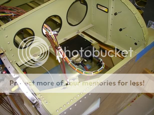
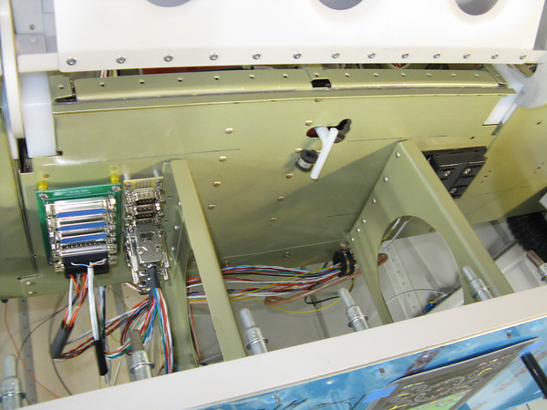
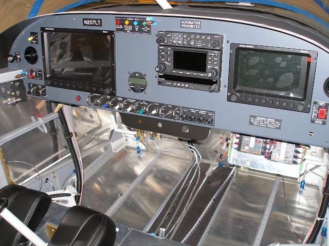
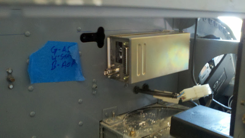
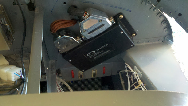
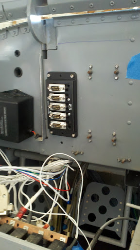
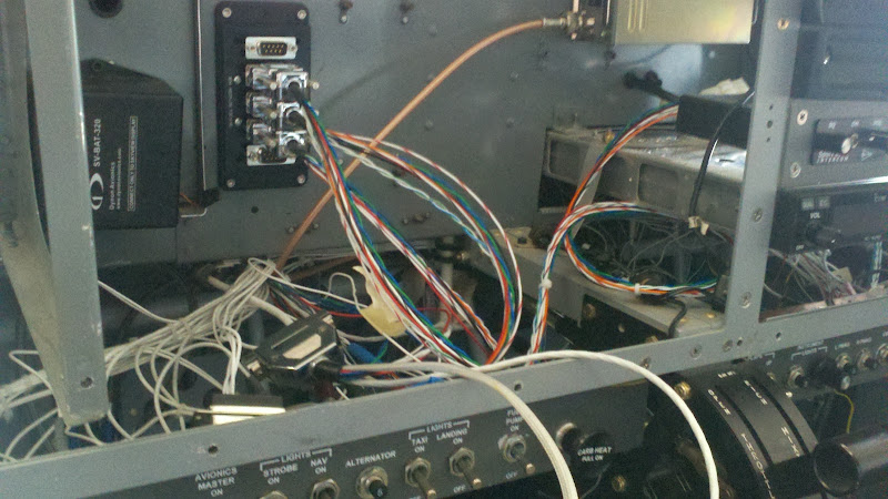
RV9A. Starting my panel. I have a Dynon 10" with a ICOM 210 Comm. Did you use the standard panel from VANS or did you order the larger panel which extends down lower for switches ? Did anybody use a hinge to swing down their panel on pilots side with the Dynon 10" mounted. Where did you mount the transponder? Engine monitor module? Where did you place a pass-thru hole or holes, for engine probe wires? Power strip for 12V? Ground strip ?

I have entered into the DYNON ZONE, All welcome to give me a idea or a picture. Much appreciated!
Thanks Guys.

Ron in Oregon
 
Last edited:
I used the standard panel from Vans and had it CNC cut by Bill at UpNorth Aviation and couldn't be happier.

Dual 10" Dynons outboard, an Xcom and caution panel and a swag of push button switches. I'm yet to install the transponder and other ancillaries though so can't help you there.
 
I used the big one.

I put a couple of steam gauges below so I used the larger panel. If I had it to do again I think I would leave out the steam.

panel.jpg
 
Standard panel for me

The oversized panel would conflict with my knees.

I put the EMS and ARINC on the left side subpanel. I also mounted the two Skyview backup batteries on that side.

I put in a few 3/4" snap bushings scattered around the subpanel and the ribs. I used almost all of them. I also installed nutplates on the lower flange of all the ribs and the subpanel, to make anchors for Adel clamps. Those came in very handy.
My blog posts for this were around January 2011.

The trig transponder went on the center rib, right side, forward of the subpanel. As mentioned, be sure to plan everything so that you'll have room to set rivets.


P3256225.JPG
 
Last edited:
I used the Afordable Panels Panel with the switch sub-panel. Great setup.

Since I did a retrofit, the transponder is mounted to the sub-panel as is the battery, EMS module, and hub.

BTW, use platenuts or rivnuts. Do not bolt through the panel as you will have to remove those items at some time in the future.

Here are some pictures taken before I cleaned up all the wiring
2012-04-14_15-59-03_291.jpg

2012-04-14_15-59-27_455.jpg

2012-04-15_11-28-56_519.jpg

2012-05-06_10-33-06_237.jpg
 
Last edited:
Well I feel stupid. I am also approaching the instrument panel phase and didn't even know there was an extended panel from Vans. I further didn't fully realize until earlier today that the two upper fuse ribs F-745L/R (TipUp) attach to the instrument panel, thus potentially obstructing instruments placed there. I plan on using the 10" Dynon Skyview and now am a bit worried if it will fit.

I have XPanel and am playing around with layouts, including the Affordable Panel. So one question I have is, for the TipUp, is there any problem fitting the 10" Skyview with either Vans standard or extended panel, or with the Affordable Panel XL? In other words is there room to center the Dynon Skyview in front of the pilot, or must it be shifted some left or right to fit?
 
It will fit!

Well I feel stupid. I am also approaching the instrument panel phase and didn't even know there was an extended panel from Vans. I further didn't fully realize until earlier today that the two upper fuse ribs F-745L/R (TipUp) attach to the instrument panel, thus potentially obstructing instruments placed there. I plan on using the 10" Dynon Skyview and now am a bit worried if it will fit.

I have XPanel and am playing around with layouts, including the Affordable Panel. So one question I have is, for the TipUp, is there any problem fitting the 10" Skyview with either Vans standard or extended panel, or with the Affordable Panel XL? In other words is there room to center the Dynon Skyview in front of the pilot, or must it be shifted some left or right to fit?

It will fit, it does take some moving of the ribs. Mine is the standard Van's panel and the Skyviews are centered to the sticks, well almost centered.
With the switches I used I had to keep the display's as high as possible which makes them have to be moved inboard slightly.
http://www.vansairforce.com/community/showpost.php?p=661954&postcount=679
 
Last edited:
I wouldn't get too hung up about exactly centering the EFIS with the stick. You won't even think about it when you are flying.
 
Well gentlemen----------------Ideas afloating! love all your pictures. I see what you mean about laying it all out first. Great idea on the nutplates under the ribs and sub panel. THATS A GO! I like the sounds of locations for the back up battery. I forgot about that one frankly. I now know where to penetrate the firewall. Thats good! Like the switch layouts. OH guys I believe the larger panel is 2" deeper and you cut the the height to fit. On that note of the panel, my buddies have said that getting in and bending the knees to fit under the panel (if you are a tall guy) is a little more difficult.. You all have made this a great discussion and keep it up. Lots of the builders are watching so thats cool. I'll be back on tommorrow night to check. Thanks guys.

Ron in Oregon 9A
 
how do you do that?

It's pretty simple, really. The F-745 rib, or ribs, are simply cut off flush at the sub-panel. The aft ends are moved left or right and re-mounted on the sub-panel wherever you wish, using some homemade angle brackets. I've already cut my left one off, anticipating a 10" screen right in front of my face.
 
Well gentlemen----------------Ideas afloating! love all your pictures. I see what you mean about laying it all out first. Great idea on the nutplates under the ribs and sub panel. THATS A GO! I like the sounds of locations for the back up battery. I forgot about that one frankly. I now know where to penetrate the firewall. Thats good! Like the switch layouts. OH guys I believe the larger panel is 2" deeper and you cut the the height to fit. On that note of the panel, my buddies have said that getting in and bending the knees to fit under the panel (if you are a tall guy) is a little more difficult.. You all have made this a great discussion and keep it up. Lots of the builders are watching so thats cool. I'll be back on tommorrow night to check. Thanks guys.

Ron in Oregon 9A

The nutplates on the ribs can also be used to attach cross angles for mounting "stuff" on. Screws inserted from below, of course...:)

cross-angles.jpg
 
Chip and Richard, Where did you get your switches from? Nice panels. Gil nice wiring job. Neat. Someday I'll learn to tie!. Hey got a answer to the stainless screws in the wing tips. You heard it first here. I took a AN507-6R6 screw to the Buffing wheel a WA-LA a polished bright head looking like chrome. The answer to the corrosion gossip with stainless steal screws. Cheaper too!
Ron in Oregon 9A
 
I bought the switches from B&C. They have small color plastic covers to give them a more organized look, I think these also came from B&C. Most of the rest was purchased from SteinAir, including the switch guards and all the wiring bits.
 
It's pretty simple, really. The F-745 rib, or ribs, are simply cut off flush at the sub-panel. The aft ends are moved left or right and re-mounted on the sub-panel wherever you wish, using some homemade angle brackets. I've already cut my left one off, anticipating a 10" screen right in front of my face.

whoa...I printed a full-scale image (actually a few % bigger) of my proposed panel (using XPanel) and put it on the Vans instrument panel:

IMG_8174.JPG


Notice the two clecos right through the 10" Dynon Skyview. So I'm going to move the left F-745 for sure. But that will leave a largish gap between the two, so I'll add another brace more-or-less in the middle.

NB. Yeah, the vents are in the wrong place. And the iPad will really be RAM-mounted so I'm not worried about that F-745 rib. I'm using a VP-200 for the electrical. And at the moment I'm planning on two pairs of throttle/mixture.
 
Last edited:
Gil Im liking that you put a couple of angle brackets underneath with nutplates. Im thinking of feeding on the idea by putting a hinge and a plate and have it drop down with one of those modules on the plate. I going to make my wiring neat like yours. It just doesn't get prettier then that, Great job Gil. Thanks for the inspiration my friend.

Thanks guys for the websites on the switches. I like them. I wondering if the the LEDs are dimable?

Stainless screws. Got a NEW IDEA here. AN507 6R6 screw I put to my buffing wheel (just the face) and WA LA. Chrome looking face but still the coated screw into Aluminum and nutplate for the threads. I have to put some out in the rain for a while to see how they do.

Ron in Oregon 9A
 
Last edited:
I moved both of the ribs inward 5". I still have just over 8" of width in the center section, and the 10" Dynon SV will fit right up to the moved rib on the left side.

IMG3928-M.jpg


The panel is very well supported by the relocated ribs, so I don't think there is any need for additional reinforcements.
 
Panel Wiring

Bruce, beautiful work!!! Do you have any pictures showing how you did wiring for both your "Ground" and "Power" fields... Thanks, Mark C.
 
Back
Top