What's new
Van's Air Force

Don't miss anything! Register now for full access to the definitive RV support community.

IFR RV-4 Schematic

FitzRX7

Well Known Member
Just finished wiring my RV-4 panel up, Garmin G3X everything. GPS-only IFR, redundant on almost all fronts, I think I have all my bases covered except dual engines.

Wanted to see what the masses thought about how we ended up designing it. I had a lot of help from some very smart people, many many thanks are in order. Especially Paige Hoffart and Jim Beyer, lots of their brain-bytes when into making this reality.

Some neat things on this are:
-$30 backup battery system instead of >$300 backup battery system.

-$5 bluetooth audio + $10 dual comm relay + built-in intercom instead of >$1000 audio panel, and also takes up way less space which was very important to me.

-$5 circuit designed by Paige to enable automatic remote on-off functionality of GDL39 with battery pack. Folks familiar with the battery pack know that it turns on when power is applied but doesn't turn off unless the power button is pressed, or the remote on/off wire is grounded and then ungrounded once power is applied. This automates that process.

uK4cUkceadzhhijIKfrewW_aIs0yXHWzFZryB5I88WungQPjbLO-2r6wVzhDmNMoSSCZpxe2MGtNxg5IBnHgkTEuQT-HsNQEnWVIZhfdPUy8AdZ9HOS4bHsks-b1cqQ4sSG9q9ZReeejeCkT3UTrmfKolXvxp5V70SaCHoI_BULb_bTVUGM-12JSl3HnYtZGjycVYROWQfQYV6RZOApFbZtDaGXrlBdSzDaAUaHziiw7VXgTsqSQu60aTQGXDqQYcjilMiUn7VOc3pafU3rieRrTgs89oPFyimM81edSu-j1BU103JVxTr0oN3-hpSnXTtcQ5_dgEiVZTkolsaFmXWjM7PpIJVsrghUkwz1O_q7q0ObPF3VHLFYZ1aLuxheloUogspMketpi84LuS1TCTovARfBdbER01m962qEzqL_aWNELHi3YqA4E7XMoerzJGtfgUuzsVqB_2A2jQ-y6LSuLLMiep2k08d4ivwQdlKZOEuVJeF6aHbW6bdkVHrTRQgd_7ByF0JvcWp-f9mae2p5Emag-qTKx55mP2rnbDXyu3Rs2_IXCisDYlpMBWDtvsqoWgV5pGaZpuigCbSlTGYYC7ORzd4M=w977-h670-no

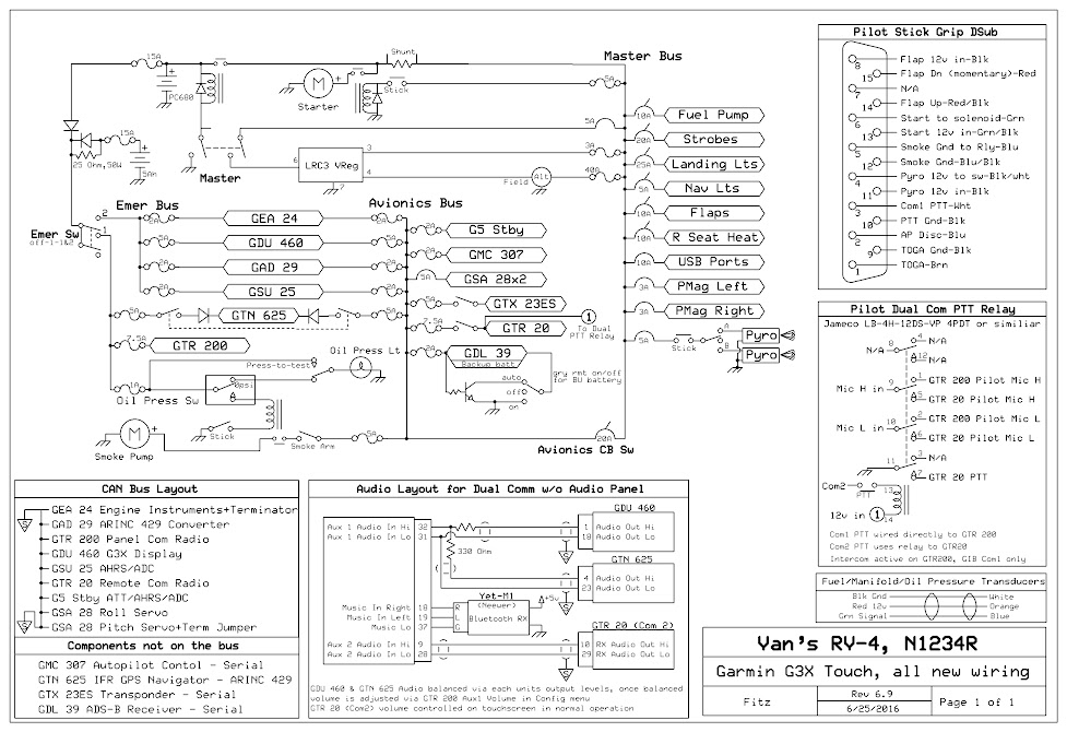
I just can't figure out how to get it to post an uncompressed image, so here's the full Res on Google Photos

Questions/comments/thoughts?

Jon
 
schematic

I have wondered about the GDL39 power down method. In my case, I took the battery off. The Garmin display will run on batteries as will the GRT EFIS. I might re-think this pwr down circuit you came up with.
Anyway, it looks good at first glance. Well designed, now practice some approaches to minimums. (personal mins !!!)
 
BTW... with that much work put in... you might add an LED that shows the starter is drawing current. The relay is 18th century after all....
 
BTW... with that much work put in... you might add an LED that shows the starter is drawing current. The relay is 18th century after all....

I have thought about that, but what I'd really like to do is power the starter switch on the stick from the oil pressure switch, so it only works when there is no oil pressure. But I need to look up the current capability of the oil switch, probably would have to run another relay which I was trying to avoid.

Jon
 
A few observations:
If com 1 fails, com 2 won't work?
Com 1 power?
Aux battery won't charge very well with a 25 ohm resistor.
 
A few observations:
If com 1 fails, com 2 won't work?
Com 1 power?
Aux battery won't charge very well with a 25 ohm resistor.

I hadn't thought of that, but yeah with Com1 failed I lose both coms, intercom, and alert tones! (But same thing happens if you have an audio panel fail I think) Guess that's what the 7600 squawk code is for!

Com1 (GTR 200) is powered by the emer bus through the aux battery. That way if the contactor or main bus or main battery fails it still has power.

Aux battery does have a reduced charge voltage with the diode voltage drop (and very little with the resistor at low current if my JV level electrical understanding is correct), but I adjusted the volt reg up to the PC680 desired charge of 14.7, so the voltage at the aux bat (PS-1250) should be close to 14v, which should work pretty good. I check the charge condition at startup with the emer bus voltage plus .5 for the diode drop.

Great comments! Keep em coming!

Jon
 
The diodes drop between 0.5 and 1 volt, depending on the type. That might not be desirable when the alternator fails and the batteries are slowly being discharged. Bob Nuckolls electrical diagrams have the diode located so that it conducts alternator current pushed by 14+ volts. At that voltage, diode voltage drop is not important.
I suggest that only one diode be used and located where the avionics circuit breaker is. In fact, that circuit breaker is an unnecessary failure point.
Connect the aux battery to the avionics bus without an additional battery or resistor.
Engine-starter voltage-spike is an old wives tale. The only danger is voltage sag during starting. The aux battery will prevent that.
 
The diodes drop between 0.5 and 1 volt, depending on the type. That might not be desirable when the alternator fails and the batteries are slowly being discharged. Bob Nuckolls electrical diagrams have the diode located so that it conducts alternator current pushed by 14+ volts. At that voltage, diode voltage drop is not important.
I suggest that only one diode be used and located where the avionics circuit breaker is. In fact, that circuit breaker is an unnecessary failure point.
Connect the aux battery to the avionics bus without an additional battery or resistor.

You can do that, but you will easily exceed the max charge current of the battery if you ever allow it to discharge (tried it once, the smell will get your attention). With a 2.5 ohm resistor, and basically no load, the standby battery will be held pretty close to bus voltage. We also used oversized Schottky diodes to minimize the drop.

Paige
 
Last edited:
I hadn't thought of that, but yeah with Com1 failed I lose both coms, intercom, and alert tones! (But same thing happens if you have an audio panel fail I think) Guess that's what the 7600 squawk code is for!

Com1 (GTR 200) is powered by the emer bus through the aux battery. That way if the contactor or main bus or main battery fails it still has power.

Aux battery does have a reduced charge voltage with the diode voltage drop (and very little with the resistor at low current if my JV level electrical understanding is correct), but I adjusted the volt reg up to the PC680 desired charge of 14.7, so the voltage at the aux bat (PS-1250) should be close to 14v, which should work pretty good. I check the charge condition at startup with the emer bus voltage plus .5 for the diode drop.

Great comments! Keep em coming!

Jon

If your audio panel fails the typical fail safe mode is direct connection to com 1 which will continue operate normally.

Your diode during transmit will be handling up to 10 amps.
 
Last edited:
If your audio panel fails the typical fail safe mode is direct connection to com 1 which will continue operate normally.

Your diode during transmit will be handling up to 10 amps.

I didn't know that about audio panels. So to lose coms with one of those Com1 and then audio panel have to fail. I'm fine with just using 7600 if my #1 radio fails, same thing that single com aircraft would have to do.

Yes, the big diode can handle that. Neat thing about the GTR 200 is in one of the setup screens it'll show you how manny amps it's drawing, 3.5A is the most I've seen from it. Now with the GDU/GAD/GEA on the Emer bus and without the avionics bus on, yes It could be close to 10A. In normal operation though, the avionics bus voltage will be slightly higher (due to the schotty diode on the Emer bus) and with the internal diodes on the G3X components they should use the higher voltage input, leaving the Emer bus to just power the GTR 200.

Jon
 
I have thought about that, but what I'd really like to do is power the starter switch on the stick from the oil pressure switch, so it only works when there is no oil pressure. But I need to look up the current capability of the oil switch, probably would have to run another relay which I was trying to avoid.

Jon

I would be concerned with getting a good connection to energize the starter if you had a situation were you needed to make a midair restart. It does happen, sometimes when you least want it to. Hope this helps. R.E.A. III #80888
 
I would be concerned with getting a good connection to energize the starter if you had a situation were you needed to make a midair restart. It does happen, sometimes when you least want it to. Hope this helps. R.E.A. III #80888

Since it's all together and flying, I'm inclined to just leave it be. Don't touch the green button after start is easy enough, and there's just one other person that flies the plane except me. The Infinity grip buttons take quite a bit of pressure to activate, that helps too.

I personally don't like the systems where you have to turn one mag off to get the starter to work, I don't think I'd remeber to do that under duress.
 
25 ohm resistor

Don't understand the purpose of the 25 ohm resistor? Even if it is a 2.5 ohm resistor, it doesn't make sense. Under high current draw, it will get hot (if it is 2.5) and if it is 25, then it will limit the battery charging as mentioned before.
 
Don't understand the purpose of the 25 ohm resistor? Even if it is a 2.5 ohm resistor, it doesn't make sense. Under high current draw, it will get hot (if it is 2.5) and if it is 25, then it will limit the battery charging as mentioned before.

It's a 2.5 Ohm, misprint on my part that will be corrected shortly.

You can do that, but you will easily exceed the max charge current of the battery if you ever allow it to discharge (tried it once, the smell will get your attention). With a 2.5 ohm resistor, and basically no load, the standby battery will be held pretty close to bus voltage.

Paige

Paige is the big brains on this one, but it's my understanding that the resistor limits the current into the Emer battery if it's significantly discharged, preventing it from popping. It is a big resistor, 50W rated with heat sinks on the case mounted to aluminum.

Also, the only current going through the resistor is for charging the aux battery. The bus current only "sees" one diode and goes straight to the emer bus.

Jon
 
The aux battery charging current depends on the battery voltage. If the battery voltage is say 10 volts, then 14.5V minus 10V = 4.5 volts dropped across the resistor. 4.5V x 4.5V divided by 2.5 ohms = 8 watts that the resistor needs to dissipate. The battery voltage would have to be less than 3.3 volts before the wattage rating of the 50 watt resistor would be exceeded. No worry about the resistor getting hot.
 
Don't understand why the emergency battery would be much different voltage than the main battery since it would be charging all the time (when engine running) like the main battery. The main battery doesn't use a current limiting resistor so why should the backup? I would take out the one diode and resistor on the emergency battery ... don't think it is needed. With that said, it won't hurt anything to leave it in either.
 
Don't understand why the emergency battery would be much different voltage than the main battery since it would be charging all the time (when engine running) like the main battery. The main battery doesn't use a current limiting resistor so why should the backup? I would take out the one diode and resistor on the emergency battery ... don't think it is needed. With that said, it won't hurt anything to leave it in either.

Well, if you ever lose your alternator, the battery will discharge. When you fix your alternator, you will be applying about 14V to the batteries. The internal resistance of the backup battery will not limit the current sufficiently (max charge current is only an amp or two for a 5AH battery) A full size battery has no problem absorbing 20 or 30 amps of charging current, a 5AH will vent and destroy itself. As I said earlier, I've seen it happen.

Using a current limiting resistor on small backup batteries isn't new. You can search the archives. I believe Brantel, Walt, and perhaps Ironflight have used similar systems.

Paige
 
Last edited:
Back
Top