What's new
Van's Air Force

Don't miss anything! Register now for full access to the definitive RV support community.

Canopy frame/rollbar

LettersFromFlyoverCountry

Well Known Member
On DWG 40, cabin frame installation side view , it indicates "fuselage station" with a measurement of 56 13/16. What is this referring to?

I'm not doing any work right now other than reading plans and this one stuck out.

Also, I'm trying to figure out where the base of the cabin frame fits in the brackets. That is, how high above the base. Looking at drawing 39, the height of the frame itself should be 17 19/32. On DWG 40, it shows a height above the inside base of the bracket of 17 28/32 (when I first looked at this, it looked like it was indicating the height from the longeron, but I'm interpreting a top line there to actually be the inboard edge of the longeron. Let me know if tis is not correct.

The front edge appears to sit abut 8/32" above the inside base. The rear edge appear to be resting just on the base of the F-631C.

However, given the original height of the frame of 17 19/32. Positioning the forward edge of the frame bottom 8/32 above the base of the F-631C bracket would yield a total of 17 27/32 or, 1/32" short of 17 7/8" callout on drawing 40.

Also on DWG 40, B-B, it appears to show the outside of the F-631C, just slighty inboard (maybe 1/64") of the side skin. When I'm measuring the width of the fuselage (to determine the width of the frame), I'm preently measuring from skin to skin. Should I adjust this meaasurement to reflect the fact that the brackets are not flush with the side skin location, or am I seeing an offset there that doesn't reeally exist?
 
Station: from FW

I called and asked when I got to that. It's from the SS firewall. That said, you may want to position the rollbar according to where it comes out when the canopy side pieces and the front deck are in place. I came out lucky, but the real trick is to get the rollbar in the right place vis-a-vis the canopy, which is located by the hinge pins after drilling. Van's answers were that it did not really matter much, but I think that it does. You may want to wait to determine the final position.

If this makes no sense, send me a private msg. with a phone number and time zone and I'll call you from my hangar.

BTW - with Van's OK, I'm using blind rivets for the last three forward on the turtle deck skin on the longeron, where F-705G bracket interferes. There's otherwise a real circular problem with what gets riveted when.
 
hevansrv7a said:
I called and asked when I got to that. It's from the SS firewall.
ah, yes. that's what I figured.

One other thing. My measurements -- all, about, 15 of them -- of the fuselage width has come out exactly what Van's plans called for -- which makes me nervous, no end. ;) But I notice that several builders have reported that when they riveted the channels to the straps, the rollbar tended to pull inward.

Is that a consistent result and, if so, does it make sense to factor, say 1/32", into the equation (a fudge factor, basically) when calculating the desired width of the rollbar itself (42 5/32)?
 
Rollbar dimensions

Many builders find that the rollbar "grows" when they rivet it, no matter how well clamped during assembly. However, it can take a little pre-load during installation to make it come out OK. I don't know what to tell you about any fudge factor, but the tendency is for the lef-right dimension to come out bigger than you expected.
h
 
How to find correct position of roll bar

If you cleco on the turtle deck skin, using all the holes you can, then the prepunched holes in the "ears" that are for 2 screws that go through the skin and into the forward side of the roll bar should be centered on the forward side for a good fit. You really want to double check this before you commit to any holes.
hh


This is one of the reasons I love VAF. I'm at this step right now, and this tidbit right here is going to save me a lot of head-scratching.
 
Nice website showing cabin frame install....

Check out Mike Bullock's website. He does a great job of showing how he did his cabin frame installation. He's on the Motherships links under RV-7's.
 
If I remember correctly station "0" is the firewall. Hope this helps. Have fun with the tip-up. Everything always seems to shift from clecos to riveting. I have built 5 of them so far and they all seem to come out a little different, but in the end it all works out well.
 
Tip-up

I built my roll bar and rear canopy bow exactly to Vans dimensions ... had to grind 1/16" to 1/8" off the inside edges at the "meeting point" to do so. A little of the bottom edges too. When riveted up, it turned out dead-on the Vans dimensions. Everything else for mounting the roll bar also fit perfectly , i.e. brackets, hdwe, etc. When it came time to put it all together it fit like a glove.
Some of the confusing height dimensions relate to the fact the roll bar sits on a backward angle, giving you more than one place/way to measure height. That vexed me a bit 'til I got it all figgered out. :)
 
The side view height is 17 7/8" from the TOP of the longeron to the TOP of the rollbar. Since my cross bar (F-705) was 3/16" lower than the top of the longeron (thickness of horizontal part of longeron angle plus latch plate), I just measured 18 1/16" to the top of the rollbar at the center from F-705 before clamping and drilling the rollbar to the brackets. I used this height and did not measure how far each leg was above the bracket except to make sure each leg was even side to side.
The 631 C brackets are supposed to be flush with the skin sides, though a hair more narrow won't matter with the overlapping turtledeck skin ears. Just finished this area, though wish I read the advice above about fore/aft spacing matching the turtledeck skin ears, though it came real close.

Also, I'm trying to figure out where the base of the cabin frame fits in the brackets. That is, how high above the base. Looking at drawing 39, the height of the frame itself should be 17 19/32. On DWG 40, it shows a height above the inside base of the bracket of 17 28/32 (when I first looked at this, it looked like it was indicating the height from the longeron, but I'm interpreting a top line there to actually be the inboard edge of the longeron. Let me know if tis is not correct.

The front edge appears to sit abut 8/32" above the inside base. The rear edge appear to be resting just on the base of the F-631C.

However, given the original height of the frame of 17 19/32. Positioning the forward edge of the frame bottom 8/32 above the base of the F-631C bracket would yield a total of 17 27/32 or, 1/32" short of 17 7/8" callout on drawing 40.

Also on DWG 40, B-B, it appears to show the outside of the F-631C, just slighty inboard (maybe 1/64") of the side skin. When I'm measuring the width of the fuselage (to determine the width of the frame), I'm preently measuring from skin to skin. Should I adjust this meaasurement to reflect the fact that the brackets are not flush with the side skin location, or am I seeing an offset there that doesn't reeally exist?
 
When measured from the SS firewall to the roll bar positioned for lineup with the holes in the skin ears, I get 57 and 3/16". The tape measure tang is about 1/16", so that make 57 1/4" from the firewall, compared to the 56 13/16" the plans call for. However, my aft top skin is just clecoed on. I have a feeling it's not going to move forward 3/8-1/2" during the riveting process, so I must be measuring something wrong.

So if I understand this correctly, the chicken is the turtle deck skin and the egg is the roll bar. Or vice versa.

Off to measure again.
 
After measuring again from the proper points, everything looks pretty good. Mike Bullock's method of using an angled piece to match up with the forward edge of the turtle deck skin ears is great. Everything falls into place.
 
Old thread, but it was the first thread I found concerning the precise location of the tip up cabin frame on the fuselage. I located and drilled the brackets using the dimension on Dwg 40 that specifies the bolts that attach the brackets to the fuselage should be 19/32” aft of the aft face of the vertical leg of the F-705G angle. This was before I even noticed the 56-13/16” station dimension. I measured that dimension on my fuselage to be 57-1/16”, which is 1/4” aft of where he drawing says it should be. I have the luxury of already having the finish kit on hand, so I placed and clamped all the forward fuselage and canopy frame parts in place and found the cabin frame to be perfectly located as is, with the forward face of the forward cabin frame bulkhead coming out exactly 1/2” aft of the aft face of the subpanel. My guess is that the 56-13/16 measurement is actually for the aft edge of the aft canopy frame instead of the forward face of the cabin frame. Maybe this should be (or is?) in the plans “gotcha” thread?

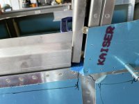
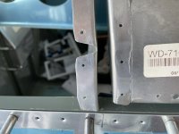
The first picture shows the aft canopy frame clamped in place 1/4” forward of the cabin frame per Dwg 48. Notice the 56-13/16 station line marked on tape on the longeron. Notice also that the the two forward holes in the turtle deck skin come out right in the middle of the forward channel of the cabin frame, as they should. The second picture shows the forward canopy frame bulkhead 1/2” aft of the F-702 subpanel. This dimension isn’t called out specifically on the drawing, but measuring off the scaled drawing that’s exactly what it is. Also, the hinges seem to be in the right location relative to the F-745 forward fuselage ribs per Dwg 47.
 

Attachments

  • 18DFCFFC-0615-45AA-A1A1-18C6EA1E5C1B.jpg
    18DFCFFC-0615-45AA-A1A1-18C6EA1E5C1B.jpg
    269.7 KB · Views: 57
  • 15F3FC4E-D79B-4558-8D22-288D6B0A397D.jpg
    15F3FC4E-D79B-4558-8D22-288D6B0A397D.jpg
    251.4 KB · Views: 58
Last edited:
Back
Top