What's new
Van's Air Force

Don't miss anything! Register now for full access to the definitive RV support community.

RV-6 Panel .dfx File

Rob Erdos

Well Known Member
Fellow RV6ators,

I'm thinking of doing the final design of my panel using Front Panel Express. Does anyone have a dfx file for a tip-up RV-6 that I could use as a starting point for the FPE panel design?

In the interest of constructive feedback, my panel design looks like this:
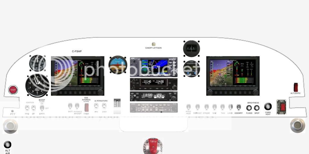
021b6df47db4ba2b8f0f4c96f130615e_zps47ba8f75.jpg


Thanks,

Rob Erdos
Ottawa
 
Compass

That's a great looking panel with lots of capability and redundancy. One thing I noticed is that you have a whiskey compass near where my vertical card compass is located. I have a lot of magnetic interference at that spot. I think it has to do with the canopy release hardware. You might want to see how your compass works in that location before cutting the hole.

John
 
These files might help.

http://thedukes.org/rv/20050526.html

Be careful that the DXF file you use may include the 1 inch of the lower panel that is bent 90 degrees away from the pilot.

The depth of the upper instruments near the tip up canopy frame is critical, but your A/S and compass should be shallow enough to clear the frame.
 
I have a -6A with a glass panel and tip-up canopy. During panel planning I wanted to move the ribs that span the distance between the sub-panel and the main panel so the Dynon D100 and D120 would be centered on the pilot and passenger. I added two ribs (with factory blessing). You need to compensate for those ribs (I don't see them in your rendering). In addition, none of the panel planning software I tried had any provision for figuring out how much clearance was needed behind the panel.

What worked for me was to make a prototype panel out of Masonite and install the actual instruments and avionics I was going to use. It's kind of old school, but there were no surprises when I cut the holes and mounted the equipment.

Please note that you will be cutting some large holes in your sub panel for those avionics. Ask me how I know.

Jim Bower
RV-6A N143DJ
St. Louis
 
....
What worked for me was to make a prototype panel out of Masonite and install the actual instruments and avionics I was going to use. It's kind of old school, but there were no surprises when I cut the holes and mounted the equipment.

....

Or use cheap acrylic from Home Depot for a true "glass panel"...:)

glass-panel.jpg
 
Gil,

That looks nice - How did you cut the Acrylic ?

Flycutter, regular drills (old blunt ones preferred), unibits and a 1.5 inch cut-off disk in a Dremel for the straight lines.

For this test oversize holes are OK...:)
 
Gil,
That is a good idea. The thought comes to mind that a regular print on photo paper or some other paper could be printed with a pattern, color, or whatever with labels and placed on the back side of a clear panel. If there was a acrylic or other clear plastic material strong enough that wouldn't crack in turbulence, it may be a new way to make putting the panel together and getting it labeled easier. Just an idea.
 
Back
Top