What's new
Van's Air Force

Don't miss anything! Register now for full access to the definitive RV support community.

Nav/Strobe Shielded Wire Wing/fuselage connector

osaleh

Active Member
Hello folks

I am running a shield wire for my Strobe/Nav Aero LEDs in the wings of my RV7A all the way to the VPX and switches. However, I would like to install a molex connector close to fuselage to unplug if i need to remove the wing. Aero install documents instructs to connect shield to ground at a one point. Where do I do that now that i have a molex connector in the middle ?

Also in the diagram attached, why do they show the shield attaching to ground at two points? i thought we are only supposed to connect shield to ground at 1 point only.
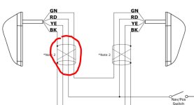
aeroled nav strobe.JPG
 
The rule of thumb is to ground a shield at only one end. However,
manufacturers instructions take precedence over rules of thumb.
They have done testing and know the best way to wire their products.
 
RFI is an issue with LED nav/strobes. For the AreoLed product (which is what I fly with) I recommend:
- Mount the nav/strobe per the instructions, but add a piece of aluminum on the inside of the wingtip, using the three nav/strobe bracket screws to make a sandwich. This provided a ground backing plate.
- Run the nav/strobe ground wire, as short a run as possible to a ring connector under one of these screws, on the inside of the wingtip.
- Run a three, #20 conductor shielded cable through the wing to the nav/strobe.
- Use a four pin Molex plug at the wingtip.
- On the nav/strobe side of the molex plug, run the shield (the ground wire) to the same screws as the nav/strobe ground. The other three nav/strobe wires connect to the three #20 conductors.

Carl
 
I thought the rule of thumb was to ground the shield on each end of a shielded wire, EXCEPT for audio circuits like headphone jacks and other audio inputs where all those are grounded at the audio source end (audio panel, comm radio or intercom as applicable). With respect to LED strobes I found differences in what Whelen and AeroLED suggest in their instructions and would go with what they have decided is the best for their respective products.
 
RFI is an issue with LED nav/strobes. For the AreoLed product (which is what I fly with) I recommend:
- Mount the nav/strobe per the instructions, but add a piece of aluminum on the inside of the wingtip, using the three nav/strobe bracket screws to make a sandwich. This provided a ground backing plate.
- Run the nav/strobe ground wire, as short a run as possible to a ring connector under one of these screws, on the inside of the wingtip.
- Run a three, #20 conductor shielded cable through the wing to the nav/strobe.
- Use a four pin Molex plug at the wingtip.
- On the nav/strobe side of the molex plug, run the shield (the ground wire) to the same screws as the nav/strobe ground. The other three nav/strobe wires connect to the three #20 conductors.

Carl
So ground the shield on the inside of the wing tip, how about the other ground of the shield? in diagram it shows two grounds for the shield. On the fuselage side , are we also running shielded wire back to VPX?
 
+1 to the above, chances are you'll never pull the wings.

I wired before wings were installed, so was left with a necessary joint. Left an extra foot on both sides of wire and soldered together with adhesive style shrink wrap (tie wrapped all of it together to avoid movement of the joints) once the wings were installed. I thought that was a tough environment that would support corrosion type issues in a connector. IF I ever have to take a wing off, it would add 1 hour of work.

Larry
 
So ground the shield on the inside of the wing tip, how about the other ground of the shield? in diagram it shows two grounds for the shield. On the fuselage side , are we also running shielded wire back to VPX?

Not exactly correct. I recommend a three #20 conductor shielded wire to the nav/strobes. One conductor is strobe power, one is nav power, one is the sync wire. The shield is the ground (the black wire) for the Nav/strobe. By doing as I suggest you create a ground plate for the Nav/strobe in the fiberglass tip (where none exists), this mitigates potential RFI issues from the LEDs. Keep the nav/strobe black wire to the plate screw short. I add a four pin Molex at the wingtip 18” or so down from the nav/strobe to allow for wingtip removal.

If you are doing standard practices, the shield ends up connected at the firewall ground tabs, just like all your other grounds. I can’t help you with VPX stuff.

Carl
 
Back
Top