What's new
Van's Air Force

Don't miss anything! Register now for full access to the definitive RV support community.

What's the theory on F1 Rocket Air Inlet Shape and Placement

Couple notes.

The intake is more or less throttled by the engine. The theoretical maximum air volume which can be put through the system is equal to

[ (RPM x displacement) / 2 ] = cubic inches per minute

Divide by 1728 for cubic feet per minute (CFM).

Volumetric efficiency is a measure of how well we actual fill the cylinders. You can define it as the ratio of actual CFM to calculated CFM from the above equation. Lacking a dyno with a mass airflow sensor, we don't have a handy way of measuring actual CFM. However, you can make a safe assumption; common engines do not achieve much better than 75 - 85% VE. That's probably quite true for the Lycoming, which has very mild cam timing. Chris doesn't account for VE, so the calculated inlet size intended to be an exact match for the air requirement is actually a wee bit oversize. Oversize is not a bad thing.

An inlet sized to strictly match the air requirement does not convert dynamic pressure to static. As Chris says, all it will do is cancel one conventional inlet loss; the engine isn't required to accelerate flow into the inlet because it is already moving.

To capture dynamic pressure you must slow the moving air. Same choice here as with a cooling intake; you can go for internal or external recovery. You can do internal recovery behind a rather small hole if you have the length for a reasonable diffuser angle. I'd suggest the hole size indicated by Chris' numbers. Even smaller might work.

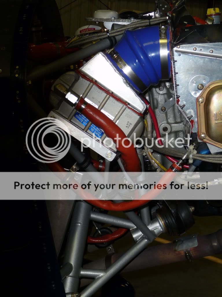
If you don't have the length, external recovery (a big hole) may be your best bet. With a modified Vans cowl and no prop extension, I needed to transition from the entry to a big flat filter is just a few inches. No way to get the desired 7 degree diffuser angle, so I went external....and thus a 4" inlet hole.

The wide mouth Rocket intake allows practical angles in the approach to a flat filter, assuming the filter can lay down more or less horizontal. Sadly, that also requires some length. The packaging gets really tight on a 4-cyl with no prop extension.
 
...Sounds like what the Formula racers often do, and what was on one of Paeser's iterations on his plane.

Any picutres Michael?

Sure, I have a few...

ic8bp2.jpg


This airplane has a rear induction sump, so the original setup is simply to run a 3" SCAT tube to the rear baffle (as some oil coolers are done). Simple and light, but no air filter. This is a problem in my area. My experiment intended to create not only a nice long divergent duct for maximum recovery, but also a large reservoir of high(er) pressure air to smooth the intake pulses out and also to provide for an effective filter.

16mjko.jpg


You will note that the straight section of tube violates the "pure" divergent duct concept, but it does allow me to vary the overall length for experimentation with a simple hoseclamp. As I said before. I could fly, adjust and fly again with essentially the same air conditions and found that it liked it best as close to the TE of the prop as I could get it.


2rhb3ie.jpg


I did run just the 3" tube without the lip for quite a while. Once I finally dusted off the lathe and turned one down, I was hopeful that it would show positive results - and it did. Despite the ID of the inlet being choked down to 2.5 inches, I still picked up a few tenths of an inch in MP. Plus it looks a whole lot better.

Overall, the filter housing picked up a little over an inch of MP, the inlet lip picked up a little more, and the location close to the prop, a touch more again. While the results were not exactly scientifically gathered, the gain was enough to convince me that I'm on the right track. So the -8 will get a cone filter mounted to the servo, and a nice "pure" divergent duct straight forward to the prop TE. Looking for a 2.5 in ID at the inlet to a 6 in ID back by the servo. Just have to make a plug for the duct and glass it up.
 
Last edited:
Interesting thread! A couple of words of explanation...not knowing any better and following some thread or other 2-3 years ago, I sealed my intake track to the cowling believing that I could readily install my lower cowling while sliding it on over the silicon inlet hose I was planning to use. I actually bought and fitted a beautiful blue silicon inlet hose that matched the even larger one I got for my baffle-to-oil-cooler plenum connection. The whole package looked really cool and worked beautifully until I tried to actually put my lower cowling on!

Both hoses were custom made, beautiful, expensive, and way too stiff to work. Soooo...I cut the access hole in the bottom of the cowling that you see in one of my earlier pictures, planning as before on clamping the hose to the FI intake and 'oil canning/collapsing' it by hand to get it to go over the exit of the air box. Still way too stiff. So, I bought the appropriate size SCEET and all has been well since. SCEET is wire wound and though pretty stiff itself, its collapsible in length with some effort. The length from the air box to the FI inlet is short but even so, I collapse the SCEET an inch/inch and a half to get it on the airbox exit collar. It is solidly clamped to the FI inlet and has a tight pressure fit to the rear of the airbox. If it's leaking, it's not showing up in performance insofar as I can tell and I don't think there's any chance of it's coming loose unless something fairly serious breaks. I've had it on and off many times and it's always right where it belongs with a 100+ hours on it now. I think it's a pretty sanitary solution, actually. I bought my silicon hoses through a racing source and it's likely that they were overbuilt for this application. There may be better choices out there, but mine were just too robust to be useful.

The other issue was that I quoted my 9,500' cruise MP the other day off my EDM 900 and got questioned on it as being too high. Sure enough, the MP on the ground with the engine off read about 1" too high. I never thought about it before that! I went into the program today and the displayed setting seemed to actually be right (same as altimeter reading---I'm at sea level), but I'll take another look at it this week when I get a chance to fly. So, the upshot there is that I'm pretty sure my MP is reading high, but I haven't found the source of it yet. If it is though, I appear to be getting nice speeds out of even lower manifold pressures than I thought!

And oh yeah... that pretty silicon connection I had from my aft baffle to my oil cooler didn't work out either. Don't have a shot of the silicon inlet hose, but the picture shows the oil cooler hose. It was custom made to the angle it makes and with the 'shake' section in the middle---still too stiff and eventually, not big enough either. YMMV in this regard!

P1000234.jpg


Lee...
 
nice pictures guys! this thread has been interesting and is timely for my alternate filter box that I have been thinking about as a winter project. Keep posting the those comments and pictures!
 
Both hoses were custom made, beautiful, expensive, and way too stiff to work.

You have a valid point Lee. Some of the 4-ply reinforced hoses are really stiff, in particular the larger diameters. Smaller diameters are available in 2-ply, but you may have already tried that route. I don't actually use the silicone hose like a hose, but rather cut rings from them use as couplers. For example, the airbox is suspended between a machined cowl intake ring and the throttle body with a silicone coupler at each end. The whole airbox yaws side to side when the engine moves on the mounts, so the couplers don't need to give very much.
 
air inlet

I had the original smiley inlet. Using K&N's formula, the square filter had approximately half the area recommended. The area above the smiley stacked full of bugs. I assumed because it was a high pressure area. I designed a 3" inlet with the bottom no lower than the smiley. I used a K&N cone filter with almost twice the area. I put an R C prop spinner cone on the end of the filter. The inlet is flush with the front of the cowl. I tried to make the airflow as straight as possible from the inlet through the filter and into the servo. It also is very easy to seal.

I made a two way flight with both the smiley and the round inlet about 20 minutes apart. I used full throttle at 2500 ft. The best I could measure I gained 1/2 inch MP and 2 MPH average GPS with the round inlet. That's the best I know how to compare results. I made a mold for the inlet and the filter cover if anyone would like to have one. It fits a standard cowl.

After having an RV-4 with no filter and seeing all the bugs and dirt in the carb, there is no way I will run without a filter even at altitude. And I still hate that fiberglass, but isn't it marvelous what an amateur can do with it!

If you would like a photo of the inlet, let me know and I'll email it to you. Jim Winings
 
...Using K&N's formula, the square filter had approximately half the area recommended.....I used a K&N cone filter with almost twice the area.

Important detail....the surface area of the filter shape is not the area of the filter media. The pleats on the cone filters are quite shallow, while many of the flat filters have pleats 7/8" to 1" deep.

This was my first try at a filtered intake:

x3zgps.jpg


The RU-3120 is a little smaller than the RU-5111 (2" small end, 4" big end, 6" long, vs 3.5", 4.4, and 5.75) but of course it was intended for a 390, not a 540. At 1400 PPH (390 at 2700 RPM) on the Airflow Performance flow bench the above setup (running with an intake bell) lost about 4" H20 as compared to the bare FM200 with the same intake bell. It also made the FM200 go rich about 13%.

An RU-1470 cylindrical filter drops about 3.3".

For comparison, the current flat plate airbox has a 1.9" H20 loss.

4" H20 is 0.294" Hg. The flat plate box improved manifold pressure by a whopping 2.1" H20, or 0.154" Hg. Not big numbers, but it all counts. FWIW, 1.9" H20 restriction is a bit less than the published numbers for a Bower with the butterfly open.

Remember, the above is pressure drop due to airbox and filter, not pressure recovery. The "perfect" design will have very little filter loss, lots of pressure recovery, and low external drag.
 
Last edited:
...This was my first try at a filtered intake...


My concept follows the same as yours except for the minor detail that I'm not necking it down at the filter and reaching further forward. I will have a 6" dia plate sandwitched between a machined filter mount nipple and the face of the servo (RSA-5). The plate will feature a lip on the outer dia to couple with the plenum/duct. My duct goes from this 6" dia at the face of the servo to the 2.5" just behind the prop. It looks like I can get it just in between the starter and alternator, plus it adds just a bit more volume which should aid in recovery.

When finished, it should be easy to instrument with an old altimeter or VSI and see if it is actually recovering any pressure.
 
Last edited:
Remember, the above is pressure drop due to airbox and filter, not pressure recovery. The "perfect" design will have very little filter loss, lots of pressure recovery, and low external drag.

Our airbox fits a bit closer to the filter than yours does, and has a sharper point on front of the filter since an r/c airplane blank spinner is attached to it. Perhaps there is a bit more pressure recovery.

On my bucketlist is to build one of these: www.flowbenchtech.com/plans.html
 
Dan,

Have you done any measurements to determine the relative contributions of the airbox designs to the pressure drops between the cone and flat filters?
 
On my bucketlist is to build one of these: www.flowbenchtech.com/plans.html

Bob, run that RU-5111 up to 1900-1950 pounds per hour for the 540 application and I'll bet a beer the RU-5111 drops 6" H20 (0.44 Hg) or more.....which is not to say it isn't better than the original airbox Jim was flying.

Don Rivera considers the cylindrical RU-1470 to be a 100-150 hp filter. The RU-1470 is 4"D x 6"L.

Have you done any measurements to determine the relative contributions of the airbox designs to the pressure drops between the cone and flat filters?

Paul, I'm not sure what you mean. Got an example?
 
Last edited:
K&N does not have data for all of their filters. Also they quote air flow per sq inch, but do not list the total area (including pleats) of the filters so it turns out to be a close guess. I have talked to them a few times when I was trying to size my intake and the best info I got out of them was that the re-oiling amount listed is directly proportional to the amount of media.

The RU-1470 re-oiling amount is 0.67 oz

The RU-5111 is 0.6 oz

My 33-2255 is 1.01 oz

Dan's 33-2124 is 1.09 oz

Don't know how accurate a comparison it is as they do not list if it is filter alone or with the applicable stock airbox as well, but a 33-2945 has a re-oil amount of 1.15 oz and was flow tested at 417.8 cfm @ 1.5" H2O.

That big difference in media amount is the reason I dropped the cone filter right away.
 
Last edited:
Pleat depth was something that I had not considered and as Dan Horton suggests it makes a big difference on actual filtering surface area.
I have a Rod Bower cone filter here with pleat depth of 0.53 inches and a flat standard F1 filter with a pleat depth of 0.79 inches. If you do the math on the external surface area of both filters then the F1 flat filter has 53 inches, or 16% more surface area then the Bower filter. It is about 7% larger then the filter that Dan is using.
Checking on the web site there are some flat filters that have even more depth which greatly increases their total surface area in respect to the foot print that they have. Based on this information, thanks dan for the hint, my proposed test airbox will have a flat filter rather then the cone shapes that I had been considering.
My goal is to see if I can get equal performance from a always filtered system then from that of my current filtered/non filtered Bower system. Please keep in mind that I am pleased with the current performance, my engine really howls on the straight ram air, I am just wondering...
This is a winter project and so do not expect results soon.

F1 filter 33-2104
Bower RU 4250
D Horton 33-2124
 
Last edited:
Dan, sorry for the late reply, I've been on the road this week.

The total delta p measured on the bench is a function not only of the filter design, but also the airbox/ shroud that surrounds the filter. This thread has been pointing (justifiably so) towards the filter configuration as the largest culprit. I'm just wondering if you or anyone else have actually tested different shroud designs around a given filter. Given the difference in total area, it appears from a functional viewpoint that Jim W's setup is actually working pretty well.

Of course, we are in the tenths of inch of Hg, so we may be at a point of diminishing returns.

I'm pleasantly surprised at how well my F1 airbox has been working (nice job, Mark!) but I am with Lee, I would like an easier way of removing and reinstalling the lower cowl.
 
Concerning the flat filters-

The RV-8 has the standard inlet mounted flat filter and it looks as though it has been "drumming" in use. The wire mesh supporting the cotton is fractured in the middle and looks like it will eventually end up going through the servo. Perhaps mine is a freak example, but this is one of the reasons I'm looking at using a cone filter (a big one) - I think it has more structural support.
 
I've been poking around searching for different filters. For our cone filter housing the RC-9640 will fit...its dimensions are slightly longer and 1/2" wider at the base. The required oil goes from 0.6 oz to 0.9 oz, which tells me it has 50% more filter area. Easy enough to compare these two between flights. I'll venture to guess the H20 drop difference between .9oz and 1.09oz is a hair on a gnat's hiney.
 
Last edited:
Tom, Mark F, gang:

After talking with Mark and considering all the options, looks like I'm going to try out the MKII Rocket inlet this winter. I don't have the dimensions of the filter box yet, but am interested in finding the filter with the largest media area (deepest pleats?) that will fit in, or can be trimmed to fit in, that filter box.

I see the filter numbers you're looking at Tom, but before I wander throught the K&N forest of part numbers, what outer dimensions should I be looking for, and how much can safely be trimmed off the edges of the filter to make a larger media filter fit? (Trimming might not be required, but I did pick up that Dan trims his to fit...just thinking ahead as a just in case).

I don't use this type of filter at the moment, so just getting the K&N gouge! Of course, if your research has already found the perfect match, please do tell! :D

Next is how to put my mod together to allow ease of removal and installation of the cowl, and how best to connect it (looking at those silicon hoses too!)

Great info here...keep er rollin'!

Cheers,
Bob

PS: Bob, I was also wondering if the filter with the RC spinner on it showed any pressure drop differential over one with no spinner (flow bench testing or in-flight testing on another plane)? Sounds like a pretty neat idea...any pictures? Any shark's teeth on the little spinner? :D
 
Last edited:
.. how much can safely be trimmed off the edges of the filter to make a larger media filter fit? (Trimming might not be required, but I did pick up that Dan trims his to fit...just thinking ahead as a just in case).

Most of 'em have a flange molded on the perimeter rubber, maybe 1/4" wide or so, easy to trim off with razor or bandsaw.

Ease on over to the auto parts store and slide a few filters out of the box.
 
I am not sure we can use the recommended oil amount as a measure of surface area as there are inconsistencies between filters, dimensions, and how much oil they use.
Some of the filters have airflow data and I would consider that to be a good indicator for performance. It is too bad that all the filters do not have that data. Perhaps there is another location that shows that data for all filters?
 
Bob
If you are going to use the Rocket filter box then I would stick with the filter recommended. There really is not much room in that box for a larger filter without a great deal of work.
 
F1 filter 33-2104

Tom,

Is that the correct K&N filter number for a textbook F1 filter box?

Where can they be purchased north of the 49th?

Thanks,

Richard
 
Will have to test to be sure

I am not sure we can use the recommended oil amount as a measure of surface area as there are inconsistencies between filters, dimensions, and how much oil they use.
Some of the filters have airflow data and I would consider that to be a good indicator for performance. It is too bad that all the filters do not have that data. Perhaps there is another location that shows that data for all filters?

Yes, I do not believe we can use that number as gospel. But it is the best indicator the tech people at K&N could give me. The dimensions listed are the total for the frame and all, not media area or pleat depth. They do not have a list of pleat dimensions, numbers, or even exact dimensions of the the media area. In fact, the first guy I spoke to said all the pleat depths were the same, even though I had held filters with different depths in my hand at an auto parts store not even 1 hour prior.

If we can find someone who can and would be willing to test them, maybe we can all send in a different model and have them tested.
 
When finished, it should be easy to instrument with an old altimeter or VSI and see if it is actually recovering any pressure.

Might be a little difficult to use a VSI for this. But an altimeter or airspeed indicator ought to work - or a manifold pressure gauge.

Dave
 
Tom, Mark F, gang:
PS: Bob, I was also wondering if the filter with the RC spinner on it showed any pressure drop differential over one with no spinner (flow bench testing or in-flight testing on another plane)? Sounds like a pretty neat idea...any pictures? Any shark's teeth on the little spinner? :D

In all seriousness I was thinking about making a couple of different shapes and trying them to see what effects they would have on pressure recovery. Kind of like how a garden hose nozzle works but in reverse.
 
Bob,

This is the question I was asking Dan--how much delta p loss can be attributed to the shroud/box design for a given filter (or conversely with a given box, how much delta p for differing filters)?

But given that the differences are in the .1" or so, my interest lies mostly in the ease of maintenance of the different configurations.

Does the cone filter system that you and Jim came up remain in place when the lower cowl is removed? I can't quite tell from the pics you supplied...thanks!
 
Paul the filter air box is bonded to the removable scoop. On the outlet of the filter there is a short piece of aluminum tube with a taper pressed into it. A short piece of 3" scat is hose clamped to the front of the servo, and when the scoop is attached (with camlocks) you just have to steer the short piece onto the tapered aluminum tube as the scoop is put into place. Fairly easy to work with.
 
Bob
If you are going to use the Rocket filter box then I would stick with the filter recommended. There really is not much room in that box for a larger filter without a great deal of work.

Roger that Tom. Since I'm going from a completely different set up, and not having peered under the skirts of many Rocket cowls, I'm not sure of the size and physical limitaitions. That will be much clearer when I have the intake(s) and the box in hand.

That being said, I was thinking along the lines of the pleat depth and filter media size we were discussing. I saw your estimates of media size (F1 33-2104 7% more area than Dan's 33-2124 and 16% more area than the RU-4250 cone). I understand those are derived estimates from your pleat depth observations. So perhaps the stock F1 filter is truly best. The trimming thought was that if we found a filter with a large increase in media area over the 2104, and it was close enough to be trimmed to fit the Rocket box, it may be worth the effort.

We may very well be dealing with "delta MP's" (if you'll allow me that term) of tenths of inches of MP (or less), so as another poster mentioned, could be diminishing returns. But here's a potetially provactaive question...how much is each 0.1" of MP worth in terms of speed? I haven't done any GPS testing with Ram Air open or closed, but I have seen the effect of opening Ram Air during SARL races. Not like I ever forgot to open the Ram Air in a race (ahem :eek:), but at race speeds and faster cruise speeds, I pick up approximately 0.7-0.9 "MP when I open the door. Observed speed increase at sea level has been 3-4 knots. Not real scientific, but very observable. That roughs out to about 1 knot per each 0.2 to 0.3 "MP. What say you guys in your experience?

So we may be pickin' nits between filters, especially as we narrow the field to a few top choices. However, if a filter swap or a little trimming nets a few tenths of an inch of MP, it might be worth it! Tom, I do understand what you mean about a larger filter that would require glass work to fit, and I appreciate that advice (mucho!). I'm just over-anal-yzing the filter media size thing a bit for fun.

yes that is the number that is on the box, you can order it from any auto shop supplier, CarQuest?

Most of 'em have a flange molded on the perimeter rubber, maybe 1/4" wide or so, easy to trim off with razor or bandsaw.

Ease on over to the auto parts store and slide a few filters out of the box.

You mean these are automotive filters!...oh the horror! :p

And I can buy it from O'Reilly or Napa (both on the way to the airport)! :D

OK, so yes, much to learn here, even on simple things like this sometime! Having been buying the rectagular black oiled filters for my different style inlet from aircraft supply venues, this is great news. If these magical, mysterious, purple-pleated marvels are available down the street, I'm a happy guy...and I will do as you recommended Dan! :)

Cheers,
Bob

PS: Tom, I think you should pose the flow versus pressure question we talked about yesterday, and then I'll pose my changing MP versus RPM question.
 
.....
You mean these are automotive filters!...oh the horror! :p

And I can buy it from O'Reilly or Napa (both on the way to the airport)! :D

.....

Those exact same filters are sold with a "FAA/PMA" stamp in the rubber seal for an increased aviation price for STC conversions.

They are called STC'd Challenger Air Filters for certified aircraft - made by K&N....:)
 
I knew I'd seen a "delaminated SCEET liner" accident report somewhere.

http://www.ntsb.gov/aviationquery/brief2.aspx?ev_id=20001212X22159&ntsbno=FTW01LA016&akey=1

As I recall in that case the engine used a rear-facing sump, and there was a long hose going to the intake that came off. It got sucked to the side of the cowling and that is what caused it to collapse. This is virtually impossible in either the stock F1 scoop our ours, even though we use a short piece of scat to connect the two.
 
Thanks, Bob--

I'll give Jim W a call this week. I'm not interested in giving up any performance, but a tenth or two is acceptable to me for a bit easier maintenance.

Now, just don't decide it's really .5".....

Thanks again!
 
As I recall in that case.....

Well heck Bob, maybe it was this one....

http://www.ntsb.gov/aviationquery/brief2.aspx?ev_id=20030716X01119&ntsbno=NYC03LA154&akey=1

...or this one...

http://www.ntsb.gov/aviationquery/brief.aspx?ev_id=20001211X15013&key=1

...or my favorite.....

http://www.ntsb.gov/aviationquery/brief.aspx?ev_id=20001212X17699&key=1

...and yes, there are more.

There's a very practical problem with a short length of SCEET tube in this application. It is impossible to know if you peeled back the edge of the liner when you shoved it on the airbox or throttle body spigot. The problem with SCAT is poor fixation of the wire coil. After enough handling the wire gets loose and moves around, allowing the tube to collapse.

Hey, seriously, I'm not here to make your life miserable. This is a discussion about air intake design, which is not entirely about dynamic pressure or filter loss. A particular design feature may have a low probability of failure, while another approach may have none. It's worth discussing.
 
Last edited:
A particular design feature may have a low probability of failure, while another approach may have none. It's worth discussing.

Very highly unlikely for the hose to collapse due to how the aluminum tube extends into the scat tubing. Its also compressed as its installed and in my case, there is only about an inch of scat that's unsupported. The filter would collapse before the scat would. My alternate air setup will completely account for both.
 
In, looking at all sides of the scat vs. silicon hose issue, as well as alternate air, a couple questions pop up:

I've searched for silicon hoses and found many exaples of 4-ply (HPS, FlexFab, etc), but not many 2-ply examples. In fact, the 2-ply units seemed to have a wire coil in them for reinforcement, much like a scat tube. So are the 4-ply units too stiff for this use, and any idea if the 2-ply units with coil reinforcement are better than scat in terms of collapse or FODing the servo? Dan, you appear to have some experience with them...any thoughts and leads to narrow the search would be very much appreciated.

If scat just works better due to the physical constraints (tight fit and engine movement), is there a good, better, best product to use?

Last, on alternate air considerations, I've seen Dan's clever solution...Bob, can you show yours as well? More data is mo betta! And from a "do we need alternate air" perspective...if its a VFR airplane (no penetration of icing conditions, etc), is alternate air a necessary item? Do most Rockets that have a single, filtered path of induction air have an alternate air path? Don't get me wrong, I'm all up for safety...just wondering what the Rocket norm is.

Thanks!

Cheers,
Bob
 
Just to make sure I'm not steering anyone wrong, my airplane has SCEET hose, not SCAT. SCEET is wire wound reinforced and has a smooth interior, which I'm told, flows a bit better the SCAT---someone posted some test results on that 2-3 years ago. Mine is just like RocketBob mentioned, there is no more than an inch to an inch and a half if it that is unsupported. I was not comfortable that I would get enough flex out of my original 4 ply silicon hose connection. The SCEET I'm using now isn't dramatically less stiff than the silicon was (an inch and a half of SCEET is stiff as heck). BUT, I'm guessing it will be flexible enough, without giving up too much strength and durability. Dan's idea for two-ply silicon is appealing, but when I was looking for the right connector material 2 years ago, I couldn't find any standard 2-ply. I'm not sure what ply my custom pieces were, but though they could be readily deformed by hand, once installed, they weren't going anywhere.

During my first year of flying which included my 'program' 40 hours, I had the cowling on and off countless times. When it came time for my annual, I replaced the original SCEET with a new piece. The old one was getting a bit shopworn around the forward edge where it 'overbites' the collar coming out of the filtered air plenum, just as you would expect. I expect a new one each year wouldn't be the worst idea in the world, but there did not look to be anything going on with the original that would make me think it was in any danger of collapsing or disconnecting from either end. It takes more than just a little effort to get it off by hand. I just don't see it coming off on it's own.

Lee...
 
The connection to the engine is a geometry problem:

2hq5ke8.jpg


The above is to scale. The Rocket box on the left is fixed to the cowl, so all relative movement is between the box spigot and the throttle body. When the throttle body moves 1/2" in response to engine torque, the connector (here 1-1/2" long) must deform a good bit. A shorter connector has it worse. And yes, reinforced silicone hose is probably too stiff for this application.

My airbox is not part of the cowl. It is suspended between an intake ring (bonded into the cowl) and the throttle body. The entire airbox yaws side to side with engine movement, so there's no shear required at the silicone connectors. Actually they are not even clamped to the airbox, which is trapped. As a bonus there is no load applied to the cowl.

.any thoughts and leads to narrow the search would be very much appreciated.

There's all kinds of stuff out there.

Here's 2-ply:

http://www.siliconehose.com/commerce/ccc1042-2-ply-silicone-connector-hose--gloss-black-color.htm

Here's non-reinforced:

http://vibrantperformance.com/catal..._1143&osCsid=d7d7d1c463ddf77c51801c6ea942353f

And you could cast your own using room temperature cured silicone or urethane rubber.

is alternate air a necessary item?

Don't plan to ever fly into known icing, but I did have visions of a cheap plastic shopping bag blowing across the runway.....
 
My inlet is fixed to the cowl as well,so I made the upper part complately flexible. The upper half of the upper section is the room cure polyeurothane which is bonded to the lower half which made with 2 layers of kevlar. The kevlar is very flexible.

I feel the odds of something filling the entry completely are very high so did not see a need for an alternate air door. I do have an alternate air path, with 3 grooves cut into the inside of the upper lip. This empties into a small chamber at the top edge of the filter and has a eurothane flap. The large radius curve should not allow any large particles to follow.
 
Good stuff, Dan. I'll get foot or two of each of those and see how they do. My engine probably shakes more than I perceive that it does from sitting in the cockpit, but in general 540's don't appear to shake nearly as much as the high compression 360 I had in my RV-4. Worth checking out. I'll get a picture of what current connector looks like when I take it apart next time. I don't think there is all that much movement, but I could certainly be wrong.

Regards,


Lee...
 
Getting back to the inlet shape itself for a moment, I'd think that for an identical placement and area, a smiley or frownie shape would have more loss than a circular shape due to the smaller area left after the boundary layer is accounted for.

Also, wouldn't the critical inlet area be determined from the low-speed climb condition - or maybe even take-off? It would have less ram air pressure but the engine (assuming constant speed prop) would be putting out max power and needing the same amount of air as at full power at high speed.

Dave
 
There's all kinds of stuff out there.

Here's 2-ply:

http://www.siliconehose.com/commerce/ccc1042-2-ply-silicone-connector-hose--gloss-black-color.htm

Here's non-reinforced:

http://vibrantperformance.com/catal..._1143&osCsid=d7d7d1c463ddf77c51801c6ea942353f

And you could cast your own using room temperature cured silicone or urethane rubber.

Thanks Dan. The volume of data and options is huge...a rec from someone that has used the stuff sure helps. I saw the first in my research, the second is new info.

Lee will get there first, so it'll be interesting to see his research play out (thanks Lee!)


Don't plan to ever fly into known icing, but I did have visions of a cheap plastic shopping bag blowing across the runway.....

Your solution is well done too. Good food for thought. Thanks!

On the smiley versus round (mentioned in another's post)...I'd like to run a comparison test between a donated round inlet (thanks Tom) and a MkII Rocket smiley (same filter airbox behind them. Winter will be "push my composites envelope" time...its good for ya, right! ;) The info will be interesting.

Cheers,
Bob
 
I'd like to run a comparison test between a donated round inlet (thanks Tom) and a MkII Rocket smiley (same filter airbox behind them.

Cool. What did you have in mind as a test setup?
 
Cool. What did you have in mind as a test setup?

Similar concept to your shrinking exit, which is something I also want to emulate...in an RV-6 kinda way (why I asked earlier about the stability of the lower cowl with two cutouts).

For the inlet test, once I have the round and smily inlets in hand, I should be able to see what would be required to make the two fit the same hole in the cowl in front of the filter airbox. Similarity of connection to the airbox is also something I need to check (and rectify if needed, to make this test work). Not having seen them yet, I may be out to lunch, but if the inlet-to-filter box connections can be made interchangeable, then I hope it will be as simple as swapping the two inlets and seeing which delivers the highest MP, etc.

Of course, is anything ever that simple? :rolleyes: Hopefully I'm not making promises I can't keep! ;)

Thoughts and suggestions welcome!

Cheers,
Bob
 
Courtland, Alabama Test October 29, 2011

Bob, it would be great if you had them ready and were able to fly from Reno, Nevada to Courtland, Alabama for the Tennessee Valley air race and straight line 2-way speed dash. I'm pretty sure that Chris Murphy would allow you to make two 2-way speed dashes if you could make the change during the speed dash time period.

This is the only unbiased speed trial that I know of and he has refined it each time so it would give you valid comparable numbers for low altitude at least. Alas, I know if that were possible you would be signed up already.

Hey, what about you Dan Horton? I'm sure you have a world beater there and I would love to see what it can do.

Bob Axsom
 
Bob, it would be great if you had them ready and were able to fly from Reno, Nevada to Courtland, Alabama for the Tennessee Valley air race and straight line 2-way speed dash. I'm pretty sure that Chris Murphy would allow you to make two 2-way speed dashes if you could make the change during the speed dash time period.

This is the only unbiased speed trial that I know of and he has refined it each time so it would give you valid comparable numbers for low altitude at least. Alas, I know if that were possible you would be signed up already.

Bob,

I'd love to go to Courtland...Chris Murphy hosts a great race, and I'd love to run the speed dash and figure out a way to launch pumpkins at the outhouse! Just a bit far given other events (hosting my In-laws' 50th Anniversary among them)...hoping for next year! And the cowl work will be a winter project...some new territory for me! Thanks for the thought though!

Hey, what about you Dan Horton? I'm sure you have a world beater there and I would love to see what it can do. Bob Axsom

Me too! Better yet, would like to meet ya too. Whether you do Courtland or not, perhaps consider the Rocket 100, last race of the year, in Taylor, TX. I'll be there along with a fairly large cast of the usual suspects (and I'll pick up my smily inlet then too...to keep 'er on topic! ;))

Cheers,
Bob
 
Back
Top