What's new
Van's Air Force

Don't miss anything! Register now for full access to the definitive RV support community.

fuel gauge floats

larrys

Well Known Member
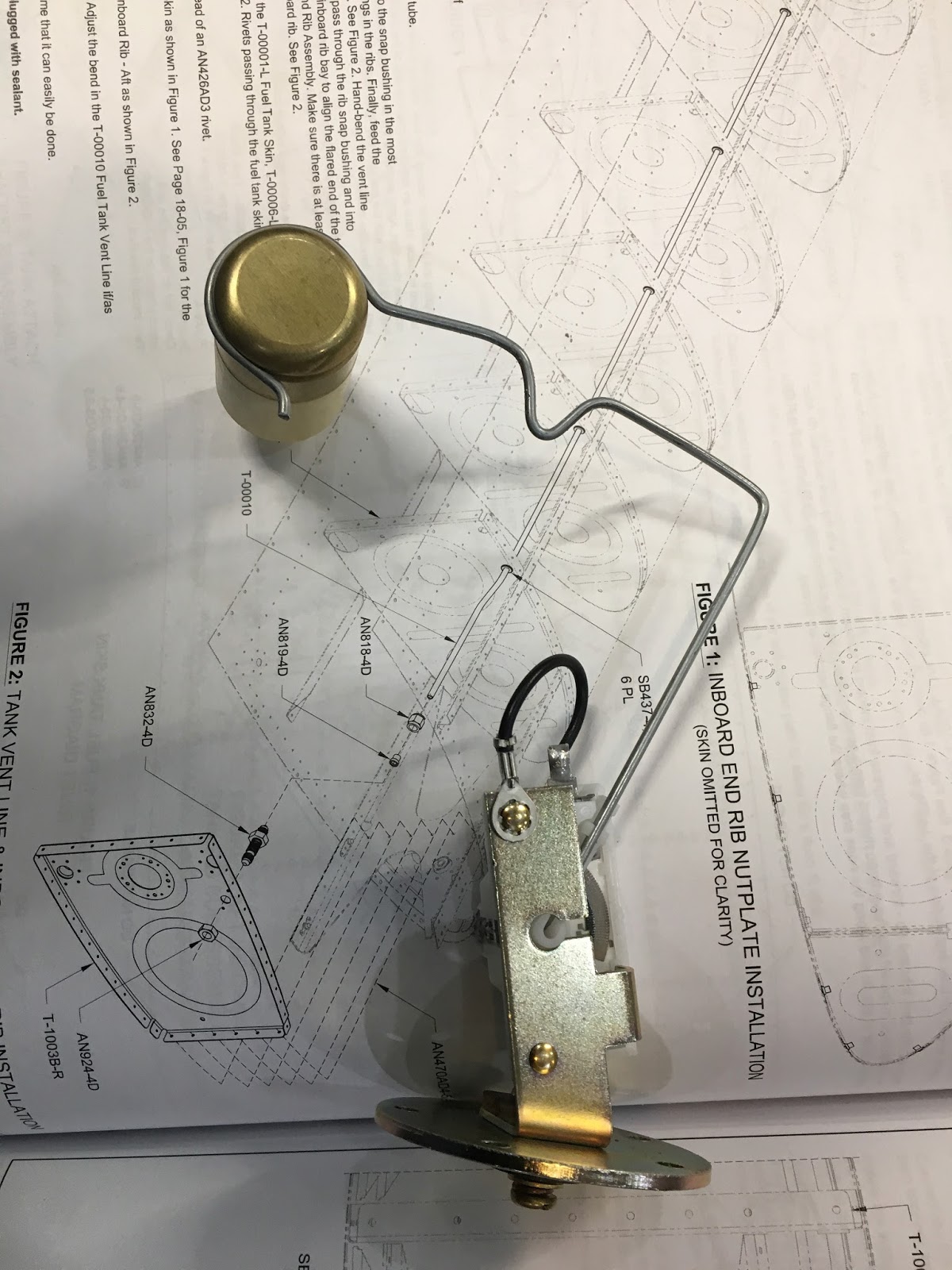
I am questions myself of fuel floats. The RV14 kit comes with 2 fuel sensor boxes. One was marked right and other left.
Seems easy. And the plans are always the left only.

When the wing is in the upright position meaning the float would be down if empty what should the reading be on the sensor? I assume with no power I would be measuring ohms.

Could the boxes be mis-marked?

And if they are opposite will Advanced flight 5600 flip high to low / low to high?
Thanks, Larry
 
If the boxes are correctly marked, the two float sets should be mirror images. You can test the resistance value at "full" and "empty" position to assure they're both correct. Be sure to carefully test the bends for clearance: as marked in the plans the bends tend to allow the floats to catch on internal tank structure. I removed the tanks from my QB wings and flipped them over about 100 times each to assure the floats would clear structure and sit in the correct position. Ended up with quite a different bend than shown in plans:

IMG_4242.jpg
 
The units are the same for L & R, the arm that gets attached comes straight and you will bend them for the L & R operation. Once it is bent, those arms are not interchangeable.
 
follow up

Thanks for the reply. On the bend and clearance I think that is OK. Is it possible to put the left in the right / right in the left. I know I needed to flip the float to miss the spar. I just don't know if the reading full ohms or no ohm reading would be correct for full or empty. The right wing is up side down right now working on wiring so the float should be "full". What would the ohm reading be?
Thanks, Larry

If the boxes are correctly marked, the two float sets should be mirror images. You can test the resistance value at "full" and "empty" position to assure they're both correct. Be sure to carefully test the bends for clearance: as marked in the plans the bends tend to allow the floats to catch on internal tank structure. I removed the tanks from my QB wings and flipped them over about 100 times each to assure the floats would clear structure and sit in the correct position. Ended up with quite a different bend than shown in plans:

IMG_4242.jpg
 
I don't recall which direction the resistance goes - thus my point about testing. If you orient the base correctly, the move the arm to full and empty positions while measuring resistance, that will become clear. The plans are clear on the orientation - see page 18-07 of plans.

I hope this makes sense.
 
30 ohms for full
240 ohms for empty.

The two sensors are not the same. There is a left and right.
They key to the holes in the tank rib which are mirror images of each other but not symmetrical, so each sensor can only be installed in the correct tank and have the screw holes line up.
 
I am so grateful for you and VAF.

Thanks! I am so grateful for you and VAF.
That is exactly what I needed to know.
Larry

30 ohms for full
240 ohms for empty.

The two sensors are not the same. There is a left and right.
They key to the holes in the tank rib which are mirror images of each other but not symmetrical, so each sensor can only be installed in the correct tank and have the screw holes line up.
 
The units are the same for L & R, the arm that gets attached comes straight and you will bend them for the L & R operation. Once it is bent, those arms are not interchangeable.

I don't believe this is correct, assuming they are the same as the 6 & 10. The arm can only be installed from one side of the assembly and the float arm always comes out of the assembly on the spar side (possible it points away from the spar. Just know they are the same). Therefore, two different assemblies are provided, with the arm attach point on different sides. In addition, the clocking of the three screws is different with the assembly in the vertical position to differentiate the two.

Larry
 
Last edited:
Back
Top