Van's Air Force
You are using an out of date browser. It may not display this or other websites correctly.
You should upgrade or use an alternative browser.
You should upgrade or use an alternative browser.
Relocation of Panel Brace? RV6 Tip-up
- Thread starter dmat
- Start date
jsharkey
Well Known Member
Panel Brace
On my RV6 I moved the LH panel brace a couple of inches to the right to clear a Dynon D100. The brace doesn't align with or connect to the forward deck rib behind the sub panel. I didn't add any other reinforcing and it is still solid after 200+ hours.
Jim Sharkey
Rv6
On my RV6 I moved the LH panel brace a couple of inches to the right to clear a Dynon D100. The brace doesn't align with or connect to the forward deck rib behind the sub panel. I didn't add any other reinforcing and it is still solid after 200+ hours.
Jim Sharkey
Rv6
BillL
Well Known Member
In the process of upgrading to a g3x(non-touch) and it looks as if the panel brace is getting in the way of the screens. I search the forums but couldn't find any info on how anyone relocated the brace(s).
Anyone do this before?
Thanks,
D
D, I had the same issue on my 7 tipper. that sub panel is in three pieces and lousy stiffness - (eyeball FEA evaluation). I might suggest an angle all along it's bottom edge for stiffness. Riveted of course.
I offset/angled the panel stiffeners with lots of little pieces for modification until they were pretty stiff. It worked for me and find that I grab the panel a lot getting in.out and under the panel maneuvers for changes/debugging. I'll post a pict if I can find it.
Zero4Zulu
Well Known Member
I used 1/2 dia. aluminum rod. Milled the ends 13.5 degrees parallel, drilled and tapped 10-32 holes in each end. Installed in line with the forward ribs. They at the upper edge of the panel and angle downward to be below my tip up canopy brace (when closed) and screwed to the sub-panel and ribs. Solid at a rock and no problem grabbing the top of the panel when climbing out.
I used 1/2 dia. aluminum rod. Milled the ends 13.5 degrees parallel, drilled and tapped 10-32 holes in each end. Installed in line with the forward ribs. They at the upper edge of the panel and angle downward to be below my tip up canopy brace (when closed) and screwed to the sub-panel and ribs. Solid at a rock and no problem grabbing the top of the panel when climbing out.
Looking at doing something similar with a new panel in my 6A tipper. Any chance you have a picture of your panel / sub-panel?
Radioflyer
Well Known Member
Given the age of the RV6 fleet, this topic is going to become more and more frequent. I hope somebody does a full documentation with pictures of their solution so that others won't have to re-invent the wheel too much.
N804RV
Well Known Member
I was just troubleshooting an erratic EMS on a friend's RV-6. He's not the builder, so he's not completely informed on some of the "mods" the builder made. Apparently this builder ran into the same problem mounting his MGL Odyssey EFIS display. His solution was to cut a notch into the support angle. Probably not the recommended solution. But, the airplane has a couple thousand hours on it without any structural issues we can find.
[email protected]
Well Known Member
I can post pictures in a couple days as I'm out of town. BUT I do not have any factory braces anymore. I use angle an made braces for the top and bottom both sides. Sure solves the brace in the way problem. I have a second RV-6 I'm working on and am going to remove the braces from the sub panel before I even put the panel in .Given the age of the RV6 fleet, this topic is going to become more and more frequent. I hope somebody does a full documentation with pictures of their solution so that others won't have to re-invent the wheel too much.
The glass panels have pretty much caused the braces to be deleted
Kinds funny. I was at Oshkosh last year and my wife wanted to sit in an RV-14 and the lady warned """Don't put your hand on the panel"""
I says !!!!Ya think somebody would have put a brace back there so you could put your hand on the panel for ingress and egress.!!! I DID!!!
You want to put your hand on my panel to climb in??? GO AHEAD It is reinforced. And I might add it is very easy to do.
My luck varies FIXIT
Ralph Inkster
Well Known Member
I cut the factory rib out & replace it with two struts, one to the top edge & one to the bottom bent flange of the istrument panel. Did this to 3 aircraft, plenty strong.
planenutz
Well Known Member
I had to move my left rib inboard a couple of inches to allow the installation of my GRT screens when I built the panel. I didn't move the right rib as I didn't have any plan to do a panel upgrade, however I now wish I'd done so. It seems to me that the best layout would be to have these ribs placed either side of the centre radio stack (or very close to it) to give you unobstructed room behind the panel... however this would also provide a few other challenges. Nothing insumountable though.
I did this installation. I had to create a very wonky looking bracket and a doubler for the subpanel to provide the offset between the panel support and the ribs in front of the subpanel. There are drawings of it available.
 vansairforce.net
Dual display setup in an RV-6
I recently finished designing and installing a dual display setup in my RV-6. The normal panel installation has two formers supporting the panel which perfectly interfere with where the displays would go in a dual setup, so some creative bracketry was required - the RV-7 structure is...
Zero4Zulu
Well Known Member


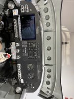
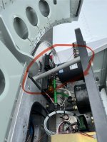
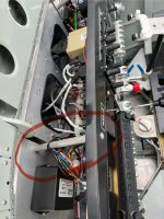
I made these solid 1/2” dia. Alum. rods. They go from near the top of the panel and reach back to the sub-panel and mount near the tip up hinges down lower, lined up with the ribs forward of the sub panel. So the rods are at an angle behind the panel and the holes in the rods are drilled and tapped perpendicular to the panel. In other words the the drilled and tapped holes don’t go straight into the end of the rods and the ends are milled to fit the back of the panel when they are mounted at an angle. Obviously they have to be positioned so they don’t interfere with the tip up canopy. I made a card board temporary to get the angles.
Easier done that explained I guess… My panel is solid as a rock and I grab the top of the panel to pull myself up departing the plane.
Also, this method leaves more room for your hands when reaching in to work on the wiring.
View attachment 60408View attachment 60409View attachment 60410
I made these solid 1/2” dia. Alum. rods. They go from near the top of the panel and reach back to the sub-panel and mount near the tip up hinges down lower, lined up with the ribs forward of the sub panel. So the rods are at an angle behind the panel and the holes in the rods are drilled and tapped perpendicular to the panel. In other words the the drilled and tapped holes don’t go straight into the end of the rods and the ends are milled to fit the back of the panel when they are mounted at an angle. Obviously they have to be positioned so they don’t interfere with the tip up canopy. I made a card board temporary to get the angles.
Easier done that explained I guess… My panel is solid as a rock and I grab the top of the panel to pull myself up departing the plane.
Also, this method leaves more room for your hands when reaching in to work on the wiring.
Thank you very much - that's perfect. I'm in the middle of cleaning up the sub-panel which was apparently "edited" multiple times to fit long 80/90 style radios. The plan is to cut and install a doubler panel to go over the whole Swiss cheese mess. I'll add the support bars to my work plan.


