wiring diagram.
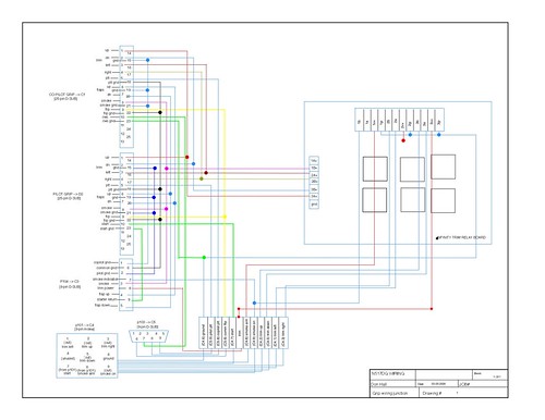
For an example just to help you wrap your head around the task, here's the wiring diagram I made for the junction where the control columns are connected to the rest of my system. The diagram itself is probably not much use outside of illustrating the nature of the task since it references wiring runs that are specific to my panel and installation.
When tackling wiring tasks, I began with pencil and graph paper, committing to a turbocad drawing when I was done with most of the erasing. The actual task of wiring was always done by simply doing what on the diagram.
Notes:
- Like others I used the infinity relay board for trim (and smoke).
- Everything in the diagram is located below the pax seat.
- I used DB connectors for most of the wiring from panel and grips, and I also used a molex for thicker gauge voltage lines to the relays.
- (not shown) For flaps, I used the vans flap relay board, actually made by AFS, since it supports multiple flap switches without negative consequence.
- (not shown) I added a switch in the panel that allows me to disable some pax grip's functions (specifically trim, smoke, flap). This is easily done by terminating the relevant pax ground wires through a switch.