Greetings,
In reference to the front page on Friday Aug 20, 2021.
Device name: MZ-30L.
Description: 3 lb, 30 amp, vacuum pad driven generator for experimental aircraft running Lycoming engines.
Company: Monkworkz.
Price: $995.
Installation manual and frequently asked questions are on the website: monkworkz.com.
A bit of commentary:
The manual is long and detailed because this device is different than anything else for this application.
It does everything I need in a single power source. I can run solely on this power source from start up to shutdown and I'm at a towered field where long taxis and ground delays are common.
I have an IFR RV-8 with dual electronic ignition and I wanted a backup power source that wasn't difficult to install, powerful enough to carry all of my typical loads, and light enough to offer a substantial weight savings over a single alternator/dual battery PC625 setup. This device checks all of those boxes for me. Onboard fuse and current shunt are bonuses on top of that.
RPM vs power output:
The manual objectively addresses this: ~900-1000 is where you will get 15 amps. But subjectively, even at 700-800 RPM I still get enough power for my plane but not 15 amps and there are periods when I'm slowing down that the battery is carrying my system. From the Sacramento Sky Ranch Manual, 2nd edition, on idle speed, pg 137: "An Idle Speed of 1100 is necessary with cold oil to create sufficient splash." Given that, 900 RPM shouldn't be a problem for anyone but you know your own airplane. For me, even doing just a lap or two around the pattern I come back with a charged battery after tower delays, and long taxis out and back.
Cooling:
It does require one more cooling duct than a traditional alternator (per Vans instructions). The cooling duct provided is identical to Vans duct material for an alternator. The duct inner diameter is 0.65", that is around 1/3 of a square inch in area. Estimating what sort of loss of cooling is difficult. How much area do all the passageways between the pressure side and exit side of the cowling add up to? For rough comparisons the inlet area of my cowling is around 64 square inches (two inlets, ~4 inches high x ~8 inches wide), so we're talking about adding something that is less than 1% of the inlet area. My engine temps are well managed and for me I think 1% is in the noise but you have to make your own decision based on your airplane.
Almost everything under the cowling requires cooling otherwise you could just tape those openings over on the front and pick up some speed. Unless we're violating the 2nd law of thermodynamics every energy conversion is less than 100% energy efficient. This applies to conversions from gas to mechanical energy (your cylinders), and mechanical to electrical (whatever you use to generate electricity). This means that heat is a byproduct and that heat needs to be liberated. This is why you have cowling inlets and blast tubes on various things under the cowl. The unit is capable of dealing with the temperatures under the cowling but it generates heat on it own that needs to be removed. The question is how much and how the cooling resource gets allocated, this additional cooling duct is in the noise for me.
For me, the additional cooling is easily justified by the other advantages of this device, mainly weight and size savings. Race pilot Dave Anders, didn't even hesitate to save 3 lbs and have the additional cooling load. He also reports that he gets more power on taxi than he did with his vacuum pad alternator. I can report that even in 115 F OATs, after a heat soak during a fuel stop, his unit was still within temperature limits that I am comfortable with. Big thanks to him for going out and sweating in those conditions.
Field testing:
There are ten prototypes in the field. Below is a list of the types of planes, and who has them. If you know them, please feel free to contact them. Most have authorized me to put prospective buyers in contact with them, so contact me if you would like to talk with them and I'll make the connection. In three cases I did the installation myself but for the rest of these I provided the manual and they were able to install it with very few or no questions. In one case, basically all I heard back was "All good so far, no issues" (Paul Rosales).
RV-8 - Bill Judge (Primary power, alternator is backup)
Please don't ask me how long it took to develop this thing.
Tailwind - 2021 Raspet Awardee [google that] (sole means of power)
Are you sure you want to be associated with me?
Harmon Rocket - Adam Pontius (Backup, dual electronic ignition)
Flawless.
RV-4 - Paul Kessel (Backup, dual electronic ignition)
Completely good! If you want to use me as a reference for people to call I am fine with that as well!
RV-4 Dave Anders (Backup, dual electronic ignition)
I think you’ve got a winner.
RV-3 - Wheeler North (Backup, dual electronic ignition)
Don't you want me to pay for this?
RV-10 - Rich Jankowski (Backup, IFR platform)
RV10, LYC IO-540 BU DC generator performs flawlessly! Easy to install!
RV-10 - Joe Waltz (Backup, IFR platform)
Glad to report that all testing has gone well.
Lancair IVP - Bob Pastusek (LOBO founder, long time Maintenance officer, 28V version on a continental TSIO 550, backup power for an IFR platform)
N437RP, a Lancair IV-P based in Ft Worth, TX. Bob Knuckles “model Z” dual 28 volt electrical system. The alternator normally runs in “on-line standby” mode at an output voltage just less than the primary alternator. In this mode it outputs 1-2 amps continuously to aircraft systems. If the primary alternator fails or is taken off-line, the standby automatically picks up the full steady-state power requirement of 14-15 amps during daylight ops and 18-20 amps at night.
I could not be happier with it!!
RV-6 - Paul Rosales (backup power)
I can’t thank you enough for this and giving me great great great peace of mind! Rosie
Letting someone else put something in your airplane is a huge decision. All of these guys volunteered and I'm incredibly grateful for that. Big thanks to all of them. They are all still running them.
I see two use cases for the MZ-30L:
1. Primary power for a magneto ignition day VFR plane where minimum weight is a priority.
2. Backup power for planes that are dependent on electrical power whether that's dual electronic iginition or IFR.
I think that the MZ-30L can do both well in almost every case, but every application is going to vary and have compromises: Such as spending $995 vs $100 at autozone or one vs two 3/4 inch ducts that probably represent a 1% change in cooling capacity.
Please contact me if you're interested: [email protected] or [email protected]. I want to get an understanding of each user's application before I sell them a unit and make sure that it is right for them. My website will eventually support online purchases.
Here is the boilerplate info about the unit:
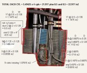
Monkworkz, LLC is proud to introduce the MZ-30L(Patent Pending) for Lycoming and similar engines. A clean sheet design to aircraft power that leverages the most recent advancements in power electronics and electromechanical machinery. The MZ-30L is a 30 amp, 3 pound, vacuum pad driven generator for 14 volt electrical systems. It can be used in backup or primary power applications and is optimized for easy installation on experimental aircraft.
The MZ-30L has several features that simplify installation and add capability, including:
*Also available: 28 V versions, and versions for Continental engines where the vacuum pad RPM is 1.5 times the crankshaft RPM.
~15 amps available at 1000 rpm on engines where the vacuum pad RPM is 1.3 times the crankshaft RPM, 30 amps available above 1800 crank RPM
In reference to the front page on Friday Aug 20, 2021.
Device name: MZ-30L.
Description: 3 lb, 30 amp, vacuum pad driven generator for experimental aircraft running Lycoming engines.
Company: Monkworkz.
Price: $995.
Installation manual and frequently asked questions are on the website: monkworkz.com.
A bit of commentary:
The manual is long and detailed because this device is different than anything else for this application.
It does everything I need in a single power source. I can run solely on this power source from start up to shutdown and I'm at a towered field where long taxis and ground delays are common.
I have an IFR RV-8 with dual electronic ignition and I wanted a backup power source that wasn't difficult to install, powerful enough to carry all of my typical loads, and light enough to offer a substantial weight savings over a single alternator/dual battery PC625 setup. This device checks all of those boxes for me. Onboard fuse and current shunt are bonuses on top of that.
RPM vs power output:
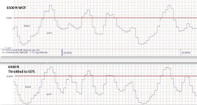
The manual objectively addresses this: ~900-1000 is where you will get 15 amps. But subjectively, even at 700-800 RPM I still get enough power for my plane but not 15 amps and there are periods when I'm slowing down that the battery is carrying my system. From the Sacramento Sky Ranch Manual, 2nd edition, on idle speed, pg 137: "An Idle Speed of 1100 is necessary with cold oil to create sufficient splash." Given that, 900 RPM shouldn't be a problem for anyone but you know your own airplane. For me, even doing just a lap or two around the pattern I come back with a charged battery after tower delays, and long taxis out and back.
Cooling:
It does require one more cooling duct than a traditional alternator (per Vans instructions). The cooling duct provided is identical to Vans duct material for an alternator. The duct inner diameter is 0.65", that is around 1/3 of a square inch in area. Estimating what sort of loss of cooling is difficult. How much area do all the passageways between the pressure side and exit side of the cowling add up to? For rough comparisons the inlet area of my cowling is around 64 square inches (two inlets, ~4 inches high x ~8 inches wide), so we're talking about adding something that is less than 1% of the inlet area. My engine temps are well managed and for me I think 1% is in the noise but you have to make your own decision based on your airplane.
Almost everything under the cowling requires cooling otherwise you could just tape those openings over on the front and pick up some speed. Unless we're violating the 2nd law of thermodynamics every energy conversion is less than 100% energy efficient. This applies to conversions from gas to mechanical energy (your cylinders), and mechanical to electrical (whatever you use to generate electricity). This means that heat is a byproduct and that heat needs to be liberated. This is why you have cowling inlets and blast tubes on various things under the cowl. The unit is capable of dealing with the temperatures under the cowling but it generates heat on it own that needs to be removed. The question is how much and how the cooling resource gets allocated, this additional cooling duct is in the noise for me.
For me, the additional cooling is easily justified by the other advantages of this device, mainly weight and size savings. Race pilot Dave Anders, didn't even hesitate to save 3 lbs and have the additional cooling load. He also reports that he gets more power on taxi than he did with his vacuum pad alternator. I can report that even in 115 F OATs, after a heat soak during a fuel stop, his unit was still within temperature limits that I am comfortable with. Big thanks to him for going out and sweating in those conditions.
Field testing:
There are ten prototypes in the field. Below is a list of the types of planes, and who has them. If you know them, please feel free to contact them. Most have authorized me to put prospective buyers in contact with them, so contact me if you would like to talk with them and I'll make the connection. In three cases I did the installation myself but for the rest of these I provided the manual and they were able to install it with very few or no questions. In one case, basically all I heard back was "All good so far, no issues" (Paul Rosales).
RV-8 - Bill Judge (Primary power, alternator is backup)
Please don't ask me how long it took to develop this thing.
Tailwind - 2021 Raspet Awardee [google that] (sole means of power)
Are you sure you want to be associated with me?
Harmon Rocket - Adam Pontius (Backup, dual electronic ignition)
Flawless.
RV-4 - Paul Kessel (Backup, dual electronic ignition)
Completely good! If you want to use me as a reference for people to call I am fine with that as well!
RV-4 Dave Anders (Backup, dual electronic ignition)
I think you’ve got a winner.
RV-3 - Wheeler North (Backup, dual electronic ignition)
Don't you want me to pay for this?
RV-10 - Rich Jankowski (Backup, IFR platform)
RV10, LYC IO-540 BU DC generator performs flawlessly! Easy to install!
RV-10 - Joe Waltz (Backup, IFR platform)
Glad to report that all testing has gone well.
Lancair IVP - Bob Pastusek (LOBO founder, long time Maintenance officer, 28V version on a continental TSIO 550, backup power for an IFR platform)
N437RP, a Lancair IV-P based in Ft Worth, TX. Bob Knuckles “model Z” dual 28 volt electrical system. The alternator normally runs in “on-line standby” mode at an output voltage just less than the primary alternator. In this mode it outputs 1-2 amps continuously to aircraft systems. If the primary alternator fails or is taken off-line, the standby automatically picks up the full steady-state power requirement of 14-15 amps during daylight ops and 18-20 amps at night.
I could not be happier with it!!
RV-6 - Paul Rosales (backup power)
I can’t thank you enough for this and giving me great great great peace of mind! Rosie
Letting someone else put something in your airplane is a huge decision. All of these guys volunteered and I'm incredibly grateful for that. Big thanks to all of them. They are all still running them.
I see two use cases for the MZ-30L:
1. Primary power for a magneto ignition day VFR plane where minimum weight is a priority.
2. Backup power for planes that are dependent on electrical power whether that's dual electronic iginition or IFR.
I think that the MZ-30L can do both well in almost every case, but every application is going to vary and have compromises: Such as spending $995 vs $100 at autozone or one vs two 3/4 inch ducts that probably represent a 1% change in cooling capacity.
Please contact me if you're interested: [email protected] or [email protected]. I want to get an understanding of each user's application before I sell them a unit and make sure that it is right for them. My website will eventually support online purchases.
Here is the boilerplate info about the unit:
Monkworkz, LLC is proud to introduce the MZ-30L(Patent Pending) for Lycoming and similar engines. A clean sheet design to aircraft power that leverages the most recent advancements in power electronics and electromechanical machinery. The MZ-30L is a 30 amp, 3 pound, vacuum pad driven generator for 14 volt electrical systems. It can be used in backup or primary power applications and is optimized for easy installation on experimental aircraft.
The MZ-30L has several features that simplify installation and add capability, including:
- Self-exciting: no external phantom current needed to generate power.
- Fast (~5 ms) electronic current limiting backed up with an integrated fuse. No need to have a panel mounted breaker or oversized “ANL” type fuse in line. Connect directly to the electrical bus wherever convenient such as the switched side of your contactor.
- Integrated current shunt: read current from a shunt provided with the device.
- Integrated current measurement with proportional voltage output: 0-4.4 volts that scales linearly with current out for input to EFIS/EIS systems or other device.
- Compact design with a compact shear coupling: Generator depth is less than 4 inches from the vacuum pad face. Diameter is less than 2.5 inches.
- Intelligent integration with other power sources: in a backup power application the MZ-30L actively monitors bus voltage and comes on line ~200 ms after bus voltage drops below spec.
- Remote Enable: Allows installation of pilot operated switch to enable/disable the device.
*Also available: 28 V versions, and versions for Continental engines where the vacuum pad RPM is 1.5 times the crankshaft RPM.
~15 amps available at 1000 rpm on engines where the vacuum pad RPM is 1.3 times the crankshaft RPM, 30 amps available above 1800 crank RPM