What's new
Van's Air Force

Don't miss anything! Register now for full access to the definitive RV support community.

timing test LS Plasma II+ ??

prkaye

Well Known Member
I'd like to do a timing test on my mag and on my Light Speed Plasma II+ Hall Effect Electronic Ignition. I've never done a timing test on either before.
I found a good video showing how to do the timing test for the mag. I've read through the instructions provided by Light Speed for doing the test on the Light Speed, but some parts of it aren't really clear to me. For example, they say to "start the engine" and then "referencing the split line of the case and your pointer, make a written note of the actual ignition timing as seen with the timing light". I don't get this at all. How am I supposed to see any of the markings on the flywheel with the engine running?

The video I saw for timing the mag showed the procedure being done by turning the prop slowly by hand and waiting for a test light to illuminate. The engine was not run. Why can't the test be done this way for the Electronic Ignition?

Does anybody know of a thread or site that has a good detailed explanation on how to do the test and timing adjustments for the Plasma II+?
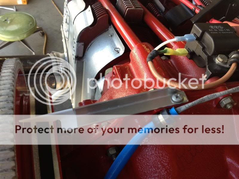
 
Has nobody done this? Is it unnecessary - are these EI systems not subject to the same kind of timing drift has happens with mags?
 
You need to get an auto timing light. It strobes the timing marks so you can see them. This whole process scares me. I do not like being that close to a swinging prop. It is at least a two man evolution, if not three. I would like a safety man to stand back and watch the whole thing. I have never put a light on my plasma III. I tried once, but my light was so old, it was not bright enough for the early morning sun. I gave up and have not tried again.
 
I've done it a number of times with a timing light, other than it being a little windy it's really not that big a deal, one should be very careful obviously. If you loosen them just enough to turn you can adjust them at the same time.

PS: I grew up working on cars and 'back then' you had to use a timing light to set the timing!
 
Last edited:
timing LSE

Phil - I assume you are using a crank triggered LSE system.. It's not really a big deal when you measure it against every other step on the plane building journey. When you start your plane the first time someone will probably be in close proximity to the prop behind it checking for leaks, etc. Just something else to be aware of and be careful around. If you have ever checked the timing on a car engine with a timing light... this is very similar.

First of all, if you are using a crank triggered ignition, make sure the 0 degree mark on the LSE ring is aligned properly to the case line on the engine. On the DC board (older style crank triggers) this is a vertical triangle with 0 degree symbol next to it. Point this right at the case split line. If you have the newer dc mini sensor, the alignment procedure is in the manual as well.

Something confusing for me with this initially was LSE's timing marks shown in the manual vs. the recommended actual timing shown on pgs 20 and 29 in the LSE manual. Notice the timing marks added to the back of the flywheel in the pic shown at 37 & 42 degrees. However, with compression ratios < 8.7:1 you will be looking for 21(+-2) degrees with the MAP tubes disconnected or pinched off and 40 (+-2) with MAP open to the boxes. I find it easier to use forceps with rubber tubing over the jaws to clamp off the map tubing. It can be a bear to pull off of the LSE brain box after install.

I had to add the additional timing marks to my flywheel since the engine builder sent it with only the factory marks with dual LSE's installed. Klaus or Aerosport will add them if you send the flywheel back to them or you can do it yourself with a automotive cam degree wheel. (I borrowed one from a local engine machine shop or you can buy just the timing wheel from Jeg's or Summit racing style shops). If you use the wheel method, line up the 0 degree mark for TDC on the wheel to the 0 degree TDC mark on your flywheel and add your timing marks. I added the marks at 21 and 40 degrees to the back of my flywheel.

So, using the light is simple. It has 3 leads... red = POS, black = GRD, 3rd lead clamps on the #1 plug wire. Connect the red and black leads of the light to your battery and the inductive (clamp on lead) to your #1 top plug wire. (If you have dual LSE's - you will do this to the top and bottom ignitions to check them independently. If you do have dual LSE's - disconnect the interconnect cables between the brain boxes to time if you are using this feature.) Attach a make shift pointer (i.e. stiff safety wire, scrap AL, etc) to the front baffle that is directly above the engine case split line. After the plane is tied down, chocked etc. have your helper start the engine and make sure your idle is set to proper RPM. Take your timing light and lean over the front skin to direct the now flashing strobe light directly in line with the pointer you made and the back of the flywheel. (it helps if you wear a cool hipster hat like Klaus is sporting in the manual) the timing marks will appear to be motionless due to the flashing strobe. Check the timing at the recommended marks with and without the MAP tubes connected or pinched off. Ideally - you will see the 21 degree mark directly inline with the pointer you made with the MAP line disconnected... and the 40 with it connected. Hopefully, its right on. If not, you need to move the sensor ring under the flywheel to adjust. Moving the sensor ring against the prop rotation direction advances the timing.

Seems like a pain but in the grand scheme of things you will know if your ignition timing and advance is working as advertised. Proper timing is a beautiful thing for your engine. Hope this helps.
 
If there's one thing that can be suggested -- do yourself a favor and get the crank sensor instead of the one that hall effect that bolts where the mag was..
 
oops

Phil - just saw you are using Hall effect... my bad. more coffee is needed on this end.
 
The mag is triggered by a set of points opening, and it is possible to measure this at zero RPM.

The LSE uses an electronic sensor, (Hall I believe) and it does not generate a usable signal unless the prop is moving fast enough.

It is possible to pull the spark plugs, and flip the prop really hard, and get the LSE to fire, but you can not check the timing this way. BTDT.

Thus, using the automotive type timing light is used.
 
The Hall sensor has a timing light built in. It is set at TDC.

From the manual......
Turn electrical power on and rotate the sensor module in the accessory case counter clockwise until the green light on the module case turns on and then off again.
Maintaining its position, fasten the sensor module with the toe clamps commonly used with Slick Magnetos.
This procedure positions the Hall Effect Module for engines normally timed at 25 degrees Before TDC (usually standard compression ratio). If your engine is normally timed at 20 degrees Before TDC (usually compression ratios of 8.7:1 or higher), the timing must be retarded 5 degrees. In this case, position the crankshaft to 5 degrees past TDC in the direction of rotation and use the procedure outlined above.

The engine timing advance can be displayed in the cockpit using the optional timing
display from LSE or any digital mV meter connected to pins 3 and 11 of the output

connector. I.e. 0.025V = 25 degrees BTDC.
On DC Mini Sensor installations, the timing display will show the actual timing advance. On other sensor installations, the displayed timing information may need to be corrected if the sensor board is not mounted in the center of the mounting slots or, in the case of the Hall Effect Module, if it is not set for 25 degree timed engines.

Hall Effect Module:
The above statement also applies to the Hall Effect Module.
Rotating the Hall Effect Module will change the actual timing of the engine but the
remote indication will not change since the TDC reference is also rotated.
If your crankshaft was not at TDC when you set your Hall Effect Modul e in Section 3.2, make a note on your display, i.e. - 5 degrees.


7.3: TIMING TEST
USING A STROBE LIGHT
To verify proper operation of the ignition system, you can check ignition timing using
a strobe light, automotive style, both on your new ignition and, should you still have
one, on the magneto. The magneto timing should be set to the manufacturers
specs.

I do not like this procedure (timing light) and have never used it on my installation. I time the Hall sensor static at TDC once a year. It has never been off of that mark

I just find it hard to believe that you can get the timing within 1 degree by holding a timing light as close as you dare an try to read the marks from leaning over the motor to center your eye with the center line of the case, better yet, the pointer that you made.... and see the timing mark on the flywheel with the prop blasting you.

I guess I just trust the designed in advance of the system.

I also see noting wrong with the Hall sensor. I have no problem with gear lash...... mags have had it for ever. And the thought of pulling the prop to make an adjustment in your timing is just bull s... period. KISS.
 
Not an RV [engine is on the wrong end of the plane :) ] but here is an index pointer for verifying dynamic timing on the LSE. Most Lycs have a machined boss on the spine that allows tapping a **small** hole to position the pointer. Checking the LSE timing with an automotive timing light is the only way to verify the ignition timing varies with MP and RPM per LSE specs. Klaus is also adamant one should verify mag timing dynamically with the same auto strobe light if a mag is retained.

Also, a very strong "concur" on leaving the Hall Effect Module off and using one of Klaus' direct crank triggers. I put 2,300+ hours on the LSE and only recently converted to direct crank trigger - something I should have done 23 years ago :(

klaus_zpsc5993672.jpg


deek
 
Last edited:
An interesting item regarding the flywheel marks. When I set mine up I had to mark flywheel in different locations as mentioned by others. How to do this accurately? I measured from the "0" out to the first set of marks already on the flywheel and the measurements seemed to make sense. I wondered how could this be a coincidence? I then checked the circumference of the flywheel between the ring gear and the main body of the flywheel and found that it measures exactly 36"!! Those old guys, before computers,were pretty sharp. This allows you to translate the 36" into 360 degrees and simply measure around the inside of the ring gear using your steel ruler to locate timing marks, using the "0" as a starting point.
There may be some smaller flywheels that do not measure 36" but the ones I have checked have. How cool is that.
 
I'm in gasman's corner on this one. I've used a the LSE Hall effect sensor for 8 years over 875 hrs. in place of a right mag without any issues. I, too, have yet to use a strobe timing light to verify the Plasma II+ timing.

On my O-360 with Sensenich fixed pitch prop on my -7A, I can run 40 - 50 degrees F lean of peak, burning 8 gph or less of 100LL or ethanol free 93 octane autogas with a TAS of 160 - 165 kts. at 8500 - 9500 MSL. How much better could it get if I fine-tuned the timing with a strobe timing light?

Mike
 
When I installed my Lightspeed ignition, I set it statically, then checked it with the timing light. The timing light showed that the static setting was perfect, so I've only done the static check since then.
 
I've used a the LSE Hall effect sensor for 8 years over 875 hrs. in place of a right mag without any issues.

Yes, some of the Hall modules work fine for extended duration and others... I can't explain it and neither can Klaus. I installed the old trigger bolt system on the flywheel of the IO-360 on the LimoEZ when it was built in '88 and enjoyed zero failures. When updating my '83 LongEZ in '91 with an EI system the Hall module was available and it seemed like a much easier way to go for the O-320 powered bird.

I won't go into details online, Klaus and I are friends, but I've replaced the aluminum housing once, the bearing twice, and the circuit board/connector 3 times. I've since sold the LimoEZ, but the new owner hasn't had any issues with the LSE or direct crank trigger. I LOVE my Plasma I EI but will no longer fly with the Hall Effect Module. Both the IO-360 and O-320 were Mattituck Red-Golds and ran very smoothly so I don't think it was a weird harmonic in the accessory case.

As a newb (and uninvited guest here on the RV forums) I sincerely wish you continued good luck with the Hall Effect Module :)

By the way, Direct Crank Trigger or Hall Effect Module, Klaus recommends using the strobe light to 1) verify low rpm, MP line disconnected timing and 2) low RPM MP advance function. How can you know if the MP advance is working correctly without putting a strobe on the engine?

deek
 
Last edited:
By the way, Direct Crank Trigger or Hall Effect Module, Klaus recommends using the strobe light to 1) verify low rpm, MP line disconnected timing and 2) low RPM MP advance function. How can you know if the MP advance is working correctly without putting a strobe on the engine?

deek


The engine timing advance can be displayed in the cockpit using the optional timing
display from LSE or any digital mV meter connected to pins 3 and 11 of the output
connector. I.e. 0.025V = 25 degrees BTDC.
 
Thanks for the input

Deek - Glad to have you on the forum. I surf several glass builder's sites from time to time and always learn a ton about different ways to solve similar problems. Good input on the LSE system from your experiences. Thanks.
 
Ah, that's right. I don't think my Plasma 1 supports that functionality, but even if it did I am old, really old and believe what I can see. I like looking at the ring gear smoothly advance with MP and by advancing the throttle seeing the RPM timing change. Admittedly this may be EZ'er in a Long since it's parked on the ground nose down and I can crouch in the rear cockpit and perform this simple test safely by myself. I do this with the EI and left mag (after setting it static with a buzz box) at every annual.

Having ignored some of Klaus' generally very good advice I have also learned it's best to have followed his directions exactly and precisely when calling for assistance :D

deek
 
Last edited:
Having ignored some of Klaus' generally very good advice I have also learned it's best to have followed his directions exactly and precisely when calling for assistance :D

deek

If you are running a Lightspeed, this is the best advise that anyone can give you.
 
ok thanks guys! I did the static check with the little green light on the Hall Effect module. The instuctions seem to suggest that the critical thing is when the light goes OFF (at TDC) and not so much where it goes on. Mine light turned off at exactly TDC as expected. I had expected it to go ON at 25 BTDC (just because I figured the light would be ON for the entire interval between firing and TDC, but the light actually came on at a different angle. Is my interpretation correct that it only matters when the light turns OFF?
 
ok thanks guys! I did the static check with the little green light on the Hall Effect module. The instuctions seem to suggest that the critical thing is when the light goes OFF (at TDC) and not so much where it goes on. Mine light turned off at exactly TDC as expected. I had expected it to go ON at 25 BTDC (just because I figured the light would be ON for the entire interval between firing and TDC, but the light actually came on at a different angle. Is my interpretation correct that it only matters when the light turns OFF?

There is no need to read things into the instructions that aren't there.
 
When I installed my Lightspeed ignition, I set it statically, then checked it with the timing light. The timing light showed that the static setting was perfect, so I've only done the static check since then.

I did the same as Kevin.
 
Back
Top