What's new
Van's Air Force

Don't miss anything! Register now for full access to the definitive RV support community.

Fitting the Spinner

Rick6a

Well Known Member
RE: Spinner Installation (Hartzell BA Constant Speed)

It is difficult for me to envision the limits of motion characteristic of a constant speed propeller and is the basis for my questions.

I have made the preliminary blade cutouts on Van's fiberglass spinner and have fitted it to the aircraft.

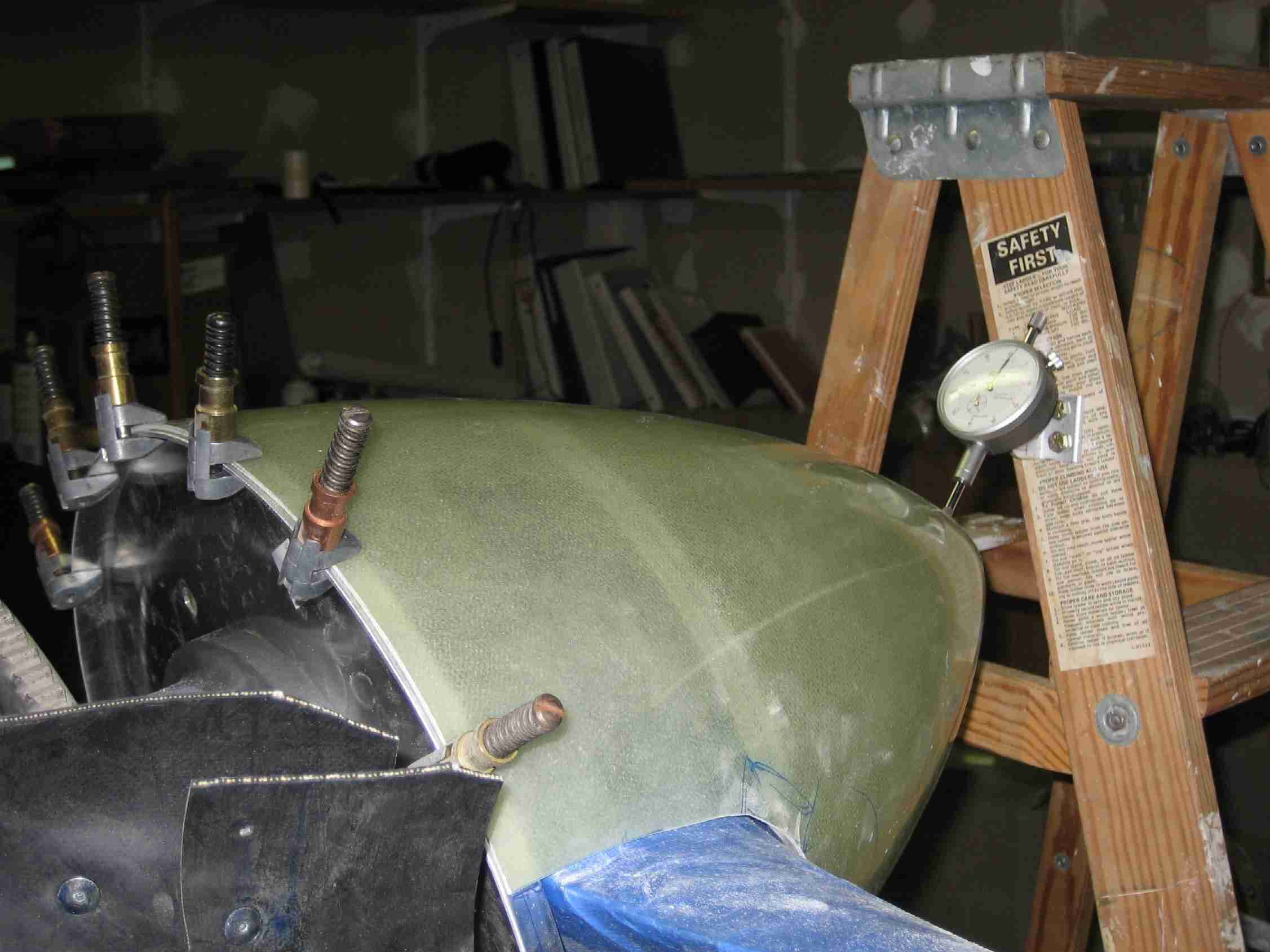
What is the recommended gap between the propeller blades and the spinner? As the first photo shows, for now I left the gap at approximately 1/8." Is this sufficient? Also, DWG C4 provides an illustration for the fabrication of filler plates to be installed directly behind the blades of a fixed pitch propeller. See photo on the right. It is unclear to me what dimensions I should seek when fabricating filler plates for the Hartzell constant speed propeller.

As you can see, my questions are based upon my lack of knowledge of the precise limits of motion of the prop blades around the hub of a constant speed propeller relative to its fixed spinner and thus the final shaping the spinner cut outs to account for such movement. Is there an approved way to rotate the prop blades to the full limits of travel around their respective hubs without causing (expensive) damage?

 
Open it up!

Hi Rick,

We recently increased the clearance on Louise's spinner because ti dug a groove in the prop....you don't want to have these too tight! We used 1/4" clearance for the new gap after looking at, and measuring the gap on several RV's at the field. I don't think I'd risk going too much closer - there just isn't much point.

As for moving the prop through it's range, take a stout broomstick, maybe three feet long. take another piece of wood a foot long. Put the broomstick against the back face of a blade, and the other stick on the front - now lash them together very tightly using non-stretching rope. The broomstick now gives you a lever to mover the prop through it's range. Now set up your clearance, and you'll be happy.

(A sanding drum on a dremel does the job neat and quick!)

Paul
 
Success!

Many thanks Paul,

Your tip worked out perfectly. I lashed a broomstick and board to one blade and quickly found out that the original 1/8" gap I cut into the spinner was woefully inappropriate and increased the overall gap to about 1/4" to insure no chaffing is possible when the blades go to coarse pitch. Later, I'll fab up the filler plates..... now that I am armed with a much clearer understanding of what is required.

Thanks again.
 
Laying out the nutplate pattern

Guys,
I'll be mounting my spinner soon, too. (RV-7) How did you lay out and drill the nut plates to the backplate? I'm leery of messing this up and haven't found it documented on any web sites yet. Can you point me to some links? Believe it or not there isn't an RV within a hundred miles of me to look at.
 
I spaced mine evenly on the front plate (6) and, after determining where the prop cut out would be, space the back plate ones evenly from prop opening to opening (7 on each half). It is very important to just use silver clecoes (and don't drill all the holes right away) and get everything fitting properly before drilling out for nutplates. If off a bit, you can still correct with bigger clecoes until you get a good fit. Then drill out the holes for the nutplates. You can see right through the epoxyglass. I marked the hole locations on the plates in black diemarker. When set inside the spinner, you could readily see the marks.

I did all the spinner fitup before the prop was on the plane. It was much easier doing it on a level bench.

Hope this helps.

Roberta

spinner1ww2.jpg
 
Roberta, and how did you get the spinner perfectly centered so it does not wobble? My current prop, the MT, comes with a pre drilled spinner, but I've had a problem with getting a spinner perfectly centered in the past.
 
I've done several spinners on the airplane with varied success. I eventually built a 3-sided "square", an upside down "U" that just fits around the spinner, with the center of the center piece marked. This way I can do the spinner on the bench by rotating it around. This method has proved to be much more accurate and repeatable.
 
I'm a little challenged!

O.K. Mel,
You're giving me a headache. :) I'm envisioning a miniature St. Louis Arch with 3 equi-distant legs standing over the spinner which is placed on a table. I line up one leg with a place I think a nutpalte should go and use the other arch legs as a reference for the other nutplates or what?
 
O.K. Mel,
You're giving me a headache. :) I'm envisioning a miniature St. Louis Arch with 3 equi-distant legs standing over the spinner which is placed on a table. I line up one leg with a place I think a nutpalte should go and use the other arch legs as a reference for the other nutplates or what?
Sorry, I didn't mean that this method spaces the screws. You can space them anyway you want. This method is for getting the spinner "centered" for a "no wobble point".
 
I put the spinner and backing plate on an old phonogragh turn table and sanded the edges until the tip spun true. Important to get the backing plate in the middle, then sand the edges of the spinner. to get the tip in concentricity.

Roberta
 
I put the spinner and backing plate on an old phonogragh turn table and sanded the edges until the tip spun true. Important to get the backing plate in the middle, then sand the edges of the spinner. to get the tip in concentricity.

Roberta

Mel and Roberta, thanks. There's always more than one way to skin a cat. I tried marking a spinning spinner with chalk and then adjusting it away from the marks but it never got very perfect. That Lycoming was not very steady.

We sold an old record player at a garage sale a few years back, should have kept it. :)
 
Got it!

What David said... thanks! I'd envisioned using a potter's wheel and mentioned it at the airport today and someone else mentioned substituting a record player since we weren't potters.:) Rick, I'll use your tip for the nutplate spacing.
 
worked for me

Here's another low-tech way:

spinner105pa.jpg

Just as shown in Van's manual. Coincidently, the Spinner was perfectly centered naturally when seated against the backplate and forward plate. The overhang on the back plate was consistent. In other words, it required no adjustment at all, as verified by the "ladder and stick" method.
 
spinner nut spacing

Guys,
I'll be mounting my spinner soon, too. (RV-7) How did you lay out and drill the nut plates to the backplate? I'm leery of messing this up and haven't found it documented on any web sites yet. Can you point me to some links? Believe it or not there isn't an RV within a hundred miles of me to look at.

After some head scratching, I used a large piece of white poster board placed flat on my work benchand and used the spinner as a template for the 13" dia circle. I found working on a flat surface using a protractor and drafting triangles,I could be very accurate while laying out the spacing for nut plates. I started by placing the spinner on the prop to determine how wide the prop blades were for the initial cuts for width and depth. These marks were transfered to my drawing to insure my spinner was symetrical. After initial fitting, there are nut plates adjacent to prop openings, I used 3/4" back from edge, Van says use 14 or 7 per side you already have 2 on each so by using my drawing and a protractor I simply divided up the remainig spaces on the paper and transfer the lines to the spinner. I found work on a flat surface with accurate lines to work from made the process a lot easier.
Hope this helps.
 
Coincidently, the Spinner was perfectly centered naturally when seated against the backplate and forward plate. The overhang on the back plate was consistent. In other words, it required no adjustment at all, as verified by the "ladder and stick" method.

Mine was the same way! Somehow, in all the excitement of mounting the spinner and making the thing looked finished, I forgot all about having to try and center the nose so it wouldn't wobble. Turned out that the part was so well made that it was perfect right out of the box. I found that with a lot of the pieces that people traditionally have trouble with - I just think the kits keep getting better and better.....would love to see the new baffle kit!

Not that I advocate people not checking.....

Paul

Hate to say the "me too" thing but mine fit so perfect, all I had to do was press it on, line the aft edges of the spinner and backplate, clamp and drill. Give it a go first folks, before you over analysis it. Now the cowl was a different story.................I think my 7 cowl was made for a prototype:eek:
 
Here is the same method I used on my RV-6. Elev. Jig with a poster board tapes to it, nail passing through the posterboard. You guys do remember those old jigs don't you? Only important thing is to have a stable fixed point in space to reference. No way Id ever just mount the spinner and assume it fits without doing this simple procedure to verify it turns true. Redoing it later would really be a pain.
spinner5.JPG
 
would love to see the new baffle kit!

Paul

The new baffle kit is right up there with all of Van's newest kits. My building partner, who finished his RV-7 two years ago, was constantly commenting about the new kit being so much easier, better fitting and designed better than the old version.
p1011066.jpg


Steve Eberhart RV-7A, O-360-A1A, Catto 3 bl., getting ready for the Kandy Apple Red (my wife picked the color)
 
There is more than one way to center a spinner...

N941WR's Web site said:
(Click on picture)
Putting the prop spinner on perpendicular is a perplexing proposition for plenty of people. (Sorry, I couldn't help myself.)

I borrowed a dial caliper from a friend (Thanks Dale!), made a simple bracket bolt it to my ladder and stabilized the ladder with two bags of led shot.

Prior to clamping the spinner in place, I marked it for where the holes are supposed to go.

With one sparkplug pulled from each cylinder the prop turned over very easily. After a few hours (days?) of turning, measuring, adjusting, etc. I was ready to drill the first hole. These measuring devices are very accurate, take your time and you will get close. I doubt you will ever attain "exact" because of the varying thickness of the fiberglass spinner.

The good news is that my spinner runs true.
 
Gap filler behind the prop needed?

I am just completing my spinner installation, and ready to do the gap filler behind the prop blades. Is this really necessary, or is it just for looks? If the gap filler is not installed, is there a structural or safety issue?

Walter
 
Back
Top