
Van's Air Force
You are using an out of date browser. It may not display this or other websites correctly.
You should upgrade or use an alternative browser.
You should upgrade or use an alternative browser.
Skyview Avionics Received!
- Thread starter Bill_H
- Start date

Bill_H
Well Known Member
A few items of note:
I received an email today that the wrong com antenna had been shipped to me and I would get a return label and a replacement com antenna. The one sent does not match the hole pattern in the fuselage. I had not noticed that it was wrong, as I haven't yet mounted the antenna.
I got the documentation kit today, all the labels and manuals and stuff. Includes the manual you keep in the plane and the metal aircraft registration plate.
The Skyview GPS Antenna screw holes did not match the holes in the plate I was sent that also attaches to the antenna shelf on the firewall. I think they sent me the old Garmin plate. I just drilled new holes and did not inform them. The plans say that the old Garmin plate will no longer be produced and give you a template for it.
WH-00046 Fuselage Harness
Received this message from Vans.
We re-terminated at the correct location.
The following apples only to those who received the WH-00046 Fuselage Harness (Finish kits shipped after August 2011)
It appears that there may be a problem with your WH-00046 harness. The twisted wire pairs for the AHRS and the Autopilot pitch servo may be spliced in the wrong location. These wires are connected to pins 17, 19, 33 & 34 on the 37 pin board connector. The distance to the splice where these 4 wires become 8 wires should be 68-69" from the 37 pin connector. From the splice, the wires to the pitch servo should be 35-36", and the wires to the AHRS should be 138-139".
Please check these measurements, if possible before the WH-00046 is installed. If it is not as above, please return the harness and we will exchange it for one with the splices on the correct location.
Apologies for the inconvenience.
Vans
Back-Ordered Conversion Wiring Harnesses
I drove over to Van's and picked up my Skyview on Feb 17th, and have been steadily pecking away at it for three weeks now. But I continue to be stymied by the two back-ordered conversion wiring harnesses. I believe they're being fabricated by SteinAir in Minneapolis and shipped to Van's for distribution to customers. Have any of you received these harnesses? I don't have the info with me at the moment to list the harness numbers. I also ordered that newfangled Dynon fuel pressure sending unit from Aircraft Spruce two weeks ago. Nothing yet.
With each successive day, I'm having to be more careful in working around the back-ordered items. They cast a long shadow across this upgrade kit. This weekend, I'll probably tear into the completed fuel tank to make the modifications for the additional corner angle brackets and frangible bolts.
It has been a challenge but I got all the wires pulled and in place except Headphone connections and AP 25 and 37 pin plug issues, Powered up Skyview and it can't find any other connections ADHARS AP EMS. Map and GPS work. It may be related to the WH 00046 issue Al brought up. I am having trouble finding the splices referd to as the harness is in.
MITCH - you opinion on the below please!
I was dreading page 42D-25. This is the page where you add the diode to the bottom relay on the firewall. This is a difficult place to get to if the engine is already installed. I found that by lifting out the oil tank (mine is still empty) and removing the two bands that hold it, I was able to get my hand in there for the tough part - bolt removal and replacement. With a very flat, small ratchet wrench the job was actually easy, only took a few minutes. Whew!
I did all of the pitot-static revisions in the tail, and installed the ADAHRS. I used foam padding and a long board to rest on and supported the tail on a table with more foam padding. I revised the OAT wires and plugged them into the ADAHRS. That leaves 4 wires that originally plugged into the DB-9 in the tail. The plans say remove them from the DB-9 totally and abandon them in place. The plans say clearly that they are no longer used. Hmmmm.....
Now on to the last major task - routing those new harnesses and the new wires to the tailcone (not looking forward to that. Tough working inside the cabin, lying flat, etc.) What goes to the tailcone in the Skyview are 2 twisted-pair sets, and a single cable with 4 wires in it. All of those go into the old DB-9 connector (now empty).
Now, something interesting. The plans say to pull the pitot tubing back from the panel all the way to the aft fuel pump. This is to clear space in the very-tightly-packed snap bushings in the main fuselage member for pulling these new wires. Then you put the pitot tube back. This doesn't sound like fun. It occurs to me that by removing those abandon-in-place wires (i.e. cut/seal them at the panel end and pull them aft) , that also frees up space - and they might be usable as pulling wires for the new ones. I will check into that.
Mitch - your opinion???
Bill, Have you done this step yet? What did you do with the 4 old wires, talked to Gus today and he seemed to think we could just pull them out. Also did you pull the pitot tube out to run the new wires or did you manage to get them in with the pitot in place?
Thanks
Bill_H
Well Known Member
I was on a business trip all week. Started running those harnesses today - and pulling the extra wire lengths down from the panel. This was very awkward and uncomfortable. (I am 6'1" and 200 pounds.) I did remove those 4 unused wires that went to the old tailcone DB9 - I removed them all the way to the OPTIONAL DB connector in the front panel. Figured that would make some room in the bundle. I also removed (as the plans state) the wire to the aux power socket. Makes some more room. I've only had to loosen the screw holding that bent metal plate above the rudder pedal tubing. I have not (yet) needed to drop the pedals assembly and hope I do not have to.
Tomorrow is the big day for running the 2 new Conversion harnesses. The OPTIONS conversion harness only has wires to the wing roots and vicinity of the headphone jacks - no big deal to run those. The Fuselage Conversion harness has 2 twisted pairs (with end pins) to go to the ADAHRS, AND a single-sheath wire containing 4 wires inside it (with pins) to the ADAHRS. I have NOT oulled back the pitot tube and hope I do not have to. We will see.
I do not have a wire spoon but fabbed one from a stiff piece of plastic tubing cut at an acute angle - I think it will work well. But I am having to remove most of the tie wraps I had previously (and painstakingly) put on. So, some fiddly work with big hands in tight places.
Gagarin737
Well Known Member
I received my Skyview kit last week. ELT is on backorder but I want to install the remote switch of the ELT in the left panel (I have to make the cutout). Is the ELT switch the same as in the old package? (and does anybody has a part number of the switch?)
Bill_H
Well Known Member
You can use your old right-side-panel as a template for making the hole in the left side panel. The switch is packed in with the ELT. I test-fit it with the old panel and it fit, before I cut the new hole. See the last pic here:
http://www.facebook.com/media/set/?set=a.151245628228677.26907.100000297210697&type=3&l=a2b29e894a
The switch is P/N 453-0023. Now, here's how to cut it so it lines up perfectly with the intercom (I am fussy about that kind of thing!). First, cut the holes for the intercom. Cleco that rear skyview support to the panel piece and use it as a guide. But do NOT cut the exact same holes - also read the paper template instructions that come with the intercom. You will have 2 holes and a slot like is on my picture. I made the slot by drilling a hole and elongating it downward with a round file. Test fit the intercom and ensure everything is good.
Now temporarily put the intercom cover plate in place. The TOP of that plate should line up with the TOP of the ELT switch's edge. Draw a very fine horizontal line to the left of the intercom plate extending its top edge line. You cut the ELT switch hole's top edge 1/16 of an inch BELOW that line! Because the intercom switch comes in from the front of the panel and overlaps the hole by 1/16 of an inch. Center the hole with the notch cutout that you can see in that clecoed support bracket.
I used a dremel for the cuts with an abrasive wheel. Worked great and they line up perfectly.
Gagarin737
Well Known Member
Thanks Bill for the reply, exactly what I need! Did you fill the ELT and intercom holes on the right before covering with the carbon vinyl or is it not noticeable after covering? I ordered the 3M stuff (3M CA-421).
Bill_H
Well Known Member
THE WORST TASK IS DONE!
Well, I just finished what I think is the most difficult task in installing the Skyview on a completed airframe with previous-style wiring already run. It is running the new wires to the tailcone!!! It worked out pretty well, here's what I did.
I did REMOVE those 4 unused wires that went to the old tailcone DB9 - I removed them all the way to the OPTIONAL DB connector in the front panel. That made some room in the bundle all the way. I also removed (as the plans state) the wire to the aux power socket - all the way. I loosened the screw holding that bent metal plate above the rudder pedals that makes the wire channel. I did NOT remove that screw or drop the pedals!
I did NOT remove the pitot tube because I dreaded putting it back up and over the rudder pedals. Maybe it would have been easier, maybe not - but I did not remove it to make room for the tasks below:
I spent a fair amount of cramped time pulling the extra wire down from the panel into the fuel-flow gadget area, making it neat. I had a bunch of foam padding in the seat area and the baggage area, and laid on my stomach with my head about where the sticks are to do this. Had to cut lots of tie wraps and use a lot. Go get yourself a big assortment of them before you start this! (6'1" 200 pounds. Not ideal for this task.)
There are 2 conversions harnesses - the FUSELAGE one and the OPTIONS one. Don't worry about the OPTIONS one - the wires from it just go out to the wing roots, not further down the more difficult path.
The other harness has the following:
2 twisted pairs that go to the tailcone. They have end pins installed.
One single-sheath wire containing 4 wires inside it (with pins).
to the ADAHRS.
One red-white wire that goes to the vicinity of the ELT.
The single-sheath wire is the biggest in diameter and I did it first. Now, wherever you feed the wire though the channel above the rudder pedals, the system blocks, or a tight snap bushing, DO NOT feed it in pins first! (Tangling with other wires will result and it just don't work.) Double it back about 3 inches and feed it through loop first with the pins trailing. This is a cramped space if you have big hands. (You know what they say about a guy with big hands? Needs big gloves.)
With this method, I got the wires through the system blocks (without loosening them) back to the aftmost snap bushing behind the flap handle. I also got them under that tie wrap right under the flaperon mixer without removing it (the great tip you can see here: http://tonytessitore.smugmug.com/RV-12Project/Finish-Kit/
It is on page 2, picture 36.)
(I do not have a wire spoon but fabbed one from a stiff piece of plastic tubing cut at an acute angle. And then I never used it!)
That aftmost snap bushing is the <insert derogatory term here.> This bad boy is the reason they say to pull the pitot tubing back to make more room there. SHould have been a bigger bushing in the first place! I got through it with each wire or pair as follows.
Sitting on the passenger side, with my left hand I held some needlenoses holding the bent-back wire. About 3/4 inch of the loop facing aft from the pliers. With my right hand I pushed down on the wire bundle going through the bushing with the handle end of a screwdriver. I then pushed the wire through the bushing with the needlenoses and subsequently fiddled with it enough so it could be reached through the belly access hole and pulled on through.
Once you are through this bushing, the rest is easy! Whew!
Well, I just finished what I think is the most difficult task in installing the Skyview on a completed airframe with previous-style wiring already run. It is running the new wires to the tailcone!!! It worked out pretty well, here's what I did.
I did NOT remove the pitot tube because I dreaded putting it back up and over the rudder pedals. Maybe it would have been easier, maybe not - but I did not remove it to make room for the tasks below:
Once you are through this bushing, the rest is easy! Whew!
I basically did the same thing tonight, except I got my wife to do most of it, little hands and a big needle nose. I have been sweating this task for a while now and it's no big deal. Now if we can just find somewhere to plug in the headsets, we'll be good to go.
.... except I got my wife to do most of it, little hands and a big needle nose.
Hope she's not reading this.

I want to install the remote switch of the ELT in the left panel
I'd also like to do this to free up right panel real estate for future 'enhancements'. I don't think this is called out in the plans and I'm pretty sure you guys are going ELSA - Did you guys run this by Vans? Or are we asking for forgiveness later?
Bill_H
Well Known Member
Vans will sell you the the panel on the right that has no ELT hole and no intercom hole. Their official demo plane is like this. And the diagrams in the new section of the plans you get for SV show it this way. Or you can do it the old way with existing parts, also mentioned in the plans. So it is an approved way to do these instruments.
[email protected]
Member
Part number for the panel on the right that has no ELT hole and no intercom hole.
Item Number: F-00035
Description: Panel R Side -1 Fuse
Cost: $14.75
Map Door is also different:
Item Number: F-00021
Description: Door, Map Box PP
Cost: 5.00
And you will might need piano hinge
Item Number: AN257-P3X6
Description: Hinge X 6"
Cost: $3.30
Item Number: F-00035
Description: Panel R Side -1 Fuse
Cost: $14.75
Map Door is also different:
Item Number: F-00021
Description: Door, Map Box PP
Cost: 5.00
And you will might need piano hinge
Item Number: AN257-P3X6
Description: Hinge X 6"
Cost: $3.30
Bill_H
Well Known Member
It was asked in another thread: "IN skyview wire harness WH-00026 there is a white wire that has a yellow/red wire spliced to it. Where does it go to?"
I had to puzzle over that also. Page 42D-23 Step 3 paragraph 2 covers it - kind of. The text description is off, Stein did not totally follow the color scheme mentioned. The long white wire is marked L458 though as mentioned in that paragraph.
These two wires (one wire from the panel that then splits) are powering the NAV lights on pin 6 of the new connectors. The previous wire you ran earlier in the build used to power both nav and strobe together. The skyview mod splits these functions so a new wire is needed. The original wire only now powers the strobes (and is connected to the noise filter.)
We are trying to keep all of the skyview q/a in this thread to make it easy on folks.
edward7048
Well Known Member
skyview
Thanks for the answer on the WH-00026 wire harnes question. I did
check and the answer is on page 42D-23.
Thanks for the answer on the WH-00026 wire harnes question. I did
check and the answer is on page 42D-23.
edward7048
Well Known Member
skywiew
does anyone know when using skyview wire harness wh-00026 and
wh-00036 where the wires for the pilot and copilot mic. and headphones
go? also the wires for the autopilot disconnect switch.
does anyone know when using skyview wire harness wh-00026 and
wh-00036 where the wires for the pilot and copilot mic. and headphones
go? also the wires for the autopilot disconnect switch.
Bill_H
Well Known Member
CLARIFICATION BELOW!!! POST MODIFIED!!! This is for those of us who installed the ORIGINAL wiring harnesses in the finish kit. Some of you may be receiving NEW wiring harnesses in the finish kit and this does not apply to you!!!
The current "answers" about the intercom wires are already in this thread.
The Skyview calls for total removal of the power wire to the "cigarette lighter" - which currently goes directly to the battery through an inline fuse (and therefore not through the ammeter). This is on page 31-10 and 45-05, wire WH-B148. The conversion harness has a replacement wire that is sensed by the ammeter. The inline fuse holder gets removed too.
There is a 3 wire bundle from the OAT sensor back to the tailcone. THAT STAYS! It just gets a different adapter on the end into the new ADAHRS. This is the wire on page 31-08.
There then remain 4 old wires going into the DB9 in the tailcone. These are twisted together. They are on page 31-12 as F190 (white/blue), F191 (white/green), F188 (white) and F189 (white/orange). These were data wires from the old magnetometer but they no longer work with the ADAHRS. The Skyview plans say to abandon them in place but I removed them all the way back to the D-dub connector they came from in the panel.
The autopilot button - page 31-12. It helps to understand what is going on. On page 31-12 you are taking cockpit lighting power and ground from the yellow/green and yellow/purple wires. You are splicing those in parallel to the AP disconnect button and the roll bar light (if you installed the lighting kit.) The AP button has 4 wires. Two are for the light and Two are for the disconnect function.
CLARIFICATION:
The Skyview plans have you cut those AP Disconnect Switch 4 wires on PAGE 42D-02 STEP 26.
YOU WILL REJOIN THEM LATER VIA MOLEX CONNECTORS ON PAGE 42D-27. FOLLOW THAT, NOT 42C-08.
HERE IS WHERE THE CONFUSION IS (including some confusion on a prior call to the mother ship!)
IGNORE THE FACT THAT YOU RECEIVED WH-00025! IT WILL NOT BE USED FOR OUR KIND OF CONVERSION. (WH-00026 is shown on page 42C-08 as doing nothing but connecting the AP disconnect switch to the AV-50000A).
NOW - a cryptic note on page 42D-15 talks about the relationship of the WH-00025 and the WH-00026. A branch connector marked AUTOPILOT of the WH-00026 will will plug into the AV-50000A!
IT WOULD BE GOOD TO GET SOME INDEPENDENT CONFIRMATION OF THIS!!!
END CLARIFICATION
In fact, you are going to eventually cut off that entire D-Sub connector that used to go to the optional AP-74 unit and seal those wires - but that doesn't interfere with crowded bundles and snap bushings which is why were are even discussing this topic! So just wait on that until you get the SV system and plans.
Hope this helps!
Last edited:
bgl
Member
wing wire
I need to know what wire to put on pin #6 at the fuselage both sides Nav wire
here is what I have found out
42D19 = 435 &436 do not run cut and shrink I don't know what they were for.
42D22 step 3 440 audio power orange/black splits to 600 and 601 orange/black take one to each side and shrink off
42D22 step 3 439 splits to 456 red/yellow and 458
I think I take the 456 to one side pin #6 and 458 other side for pin #6 Nav light
thanks
Bayne
Bill_H
Well Known Member
See about 5 posts back. Pin 6 on the fuselage-to-wing connector is a new wire for nav light power. The problem is identifying which wire it is, because the text description in the plans does not exactly match what Stein sent (well, what they sent to me anyway.)
+++
"IN Skyview wire harness WH-00026 there is a white wire that has a yellow/red wire spliced to it. Where does it go to?"
Reply: I had to puzzle over that also. Page 42D-23 Step 3 paragraph 2 covers it - kind of. The text description is off, Stein did not totally follow the color scheme mentioned. The long white wire is marked L458 though, as mentioned in that paragraph.
These two wires (one wire from the panel that then splits) are powering the NAV lights on pin 6 of the new connectors. The previous wire you ran earlier in the build used to power both nav and strobe together. The skyview mod splits these functions so a new wire is needed. The original wire only now powers the strobes (and is connected to the noise filter on the pilot side.)
ScottSchmidt
Well Known Member
Couple of questions / Thanks Bill
I have the same question. Does anyone know what the WH P440 that splits into P600 and P601 are for?
And why if you have the lighting kit you cut 435 and 436 but if you don't you run them and them heat shrink over the ends? What are these for?
Also, what is the RED/WHT wire that you put an ES 320559 on and tie wrap it to the bottom of the ELT for? In the ELT instructions it does not connect to anything. Any ideas?
Thanks Bill for your write-ups on this. It mostly makes sense other than the things I listed above.
You definitely have to jump back and forth between sections even after reading it 5 times to fully understand what everything is doing.
42D19 = 435 &436 do not run cut and shrink I don't know what they were for.
42D22 step 3 440 audio power orange/black splits to 600 and 601 orange/black take one to each side and shrink off
I have the same question. Does anyone know what the WH P440 that splits into P600 and P601 are for?
And why if you have the lighting kit you cut 435 and 436 but if you don't you run them and them heat shrink over the ends? What are these for?
Also, what is the RED/WHT wire that you put an ES 320559 on and tie wrap it to the bottom of the ELT for? In the ELT instructions it does not connect to anything. Any ideas?
Thanks Bill for your write-ups on this. It mostly makes sense other than the things I listed above.
You definitely have to jump back and forth between sections even after reading it 5 times to fully understand what everything is doing.
I would assume 600 & 601 are power wires for powered headsets?
Don't know why you cut 435 and 436, but it sounded easy to do, lol.
Again, have no idea what the red/wht wire is for, just crimp it and be done with it.
One thing I found out about the ELT is, it's calling for a gry/pur #??? wire for the gps and I have a wht wire # 4?? for the gps. I asked gus about this, he said to NOT hook anything to the blue wire coming from the ELT. Just put heat shrink on the wht wire and coil it up. Also this is a shield wire so make sure not to ground the wire to the shield.
Bill_H
Well Known Member
Here's what I think is going on. Remember, a very similar harness is being built for people building the finish kit. So the instructions are a bit of a jumble.
I don't think that the wires to the headset area are for power. I think they are an independent ground return. It mentions that on the page that discusses the merits of the conversion harnesses vs pin swapping vs running a totally new harness. The current headset jacks are grounded to the airframe.
It makes sense to run and tie off the new lighting wire if you did not buy the lighting kit. It is there if the lighting kit is purchased in the future, and the extra wire is needed to separate the nav and strobe function.
I think that the red/white wire to the ELT area could be power for the roll bar light. Or, it could be the same as the GPS-out wire that we have already run - except the one we already ran assumed a separate GPS in the panel so maybe the new one comes from the Skyview GPS function. Or maybe it is needed for some other ELT that Van's is considering. Maybe it is gray/purple in the new finish-kit non-conversion harness. Not sure about that one!
ScottSchmidt
Well Known Member
One thing I found out about the ELT is, it's calling for a gry/pur #??? wire for the gps and I have a wht wire # 4?? for the gps. I asked gus about this, he said to NOT hook anything to the blue wire coming from the ELT. Just put heat shrink on the wht wire and coil it up. Also this is a shield wire so make sure not to ground the wire to the shield.
So is there any GPS data feeding the ELT?
I assumed the blue wire would connect to the GPS wire we ran previously. That is definitely not clear in the plans.
Update: The Skyview does not output the right GPS data to the ELT and Van's made the decision not to add the converter that costs a couple of hundred dollars unless you want. What I did not realize is how accurate the ELT is without a GPS. I was told it is accurate up to 200 yards with no GPS. That is plenty accurate for me and not worth the cost of updating. Make sure the GPS data wire that is in the plane is protected and does not ground out. It can cause your GPS to not work.
Last edited:
Thanks for the Update Scott!!
I am wondering how many others have their order form and cash to Vans but haven't heard anymore about shipping of their Skyview.
March 5th I was emailed by Vans (Anna) they were waiting for more Skyviews to arrive from Dynon, I would get an email conformation of shipping, but as of today nothing heard.
My hope is as the current builders are experiencing issues that Vans has put a "slight" hold on shipping to update some instructions or include some back-ordered equipement.
It's not that I am frustrated but I have had mixed messages on this Skyview upgrade since this time last year.
Be patient.......I'm trying.
UPDATE: I just got the email my 2 Skyview boxes are in route. I have seen where many builders say their boxes just "show up" without warning but I did get email and tracking numbers.
Last edited:
DonFromTX
Well Known Member
I guess I am in somewhat the same boat. I sent Vans the cash on 1 February, the first day they announced they were taking orders, and told them I was waiting for the Skyview kit, and got a response on 7 Feb, saying they would be getting me more information in 2-3 weeks. It has been over 5 weeks and not even a word from them. I emailed for status and have not received a reply. I don't know how many of us are still waiting, but this is sure disappointing.
Last edited:
engineerofsorts
Well Known Member
Clues to when your Skyview has shipped
My only real clue that the Skyview panel was shipped was from monitoring my credit card charges--when about $160 charge from Van's appeared, it was about a week. for the Fedex (land, not air) to get to me. No notification was received via email from Van's or Fedex--no tracking number--just got lucky that my wife was home to sign for it when it did arrive.
My only real clue that the Skyview panel was shipped was from monitoring my credit card charges--when about $160 charge from Van's appeared, it was about a week. for the Fedex (land, not air) to get to me. No notification was received via email from Van's or Fedex--no tracking number--just got lucky that my wife was home to sign for it when it did arrive.
Last edited:
Bill_H
Well Known Member
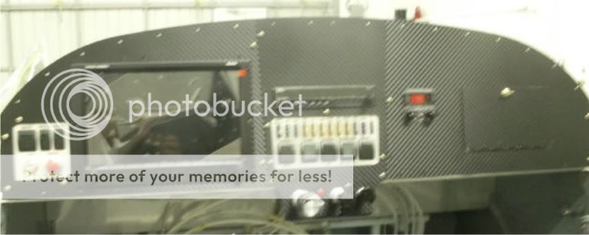
PANEL PICS!
Panel is almost done! Here are two pics. Still some placards to put on. I went with the non-countersunk screws with silver washers - I like the look with the background. The engine control labels and N-number were made at a local trophy shop. (The screws under the engine label are countersunk.)
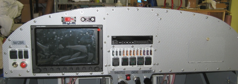
and another:
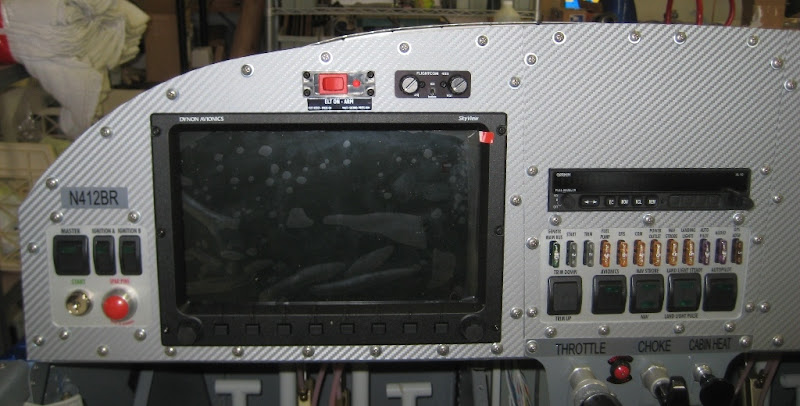
Smoke test and engine start soon!!!
Panel is almost done! Here are two pics. Still some placards to put on. I went with the non-countersunk screws with silver washers - I like the look with the background. The engine control labels and N-number were made at a local trophy shop. (The screws under the engine label are countersunk.)
and another:
Smoke test and engine start soon!!!
Bill_H
Well Known Member
SMOKE TEST PASSED! But I only ran it at first for about 3 seconds because the fuel pump is really noisy running dry. (I had forgotten to pull that fuse. I am worried that maybe it was TOO noisy but won't know until I run it with fuel.)
The Skyview setup went fine. I had gone through the installation/setup manual first but still - a few tips.
I did NOT notice if the panel bottom two fans ran during those brief 3 seconds. They were NOT running after I pulled the fuel pump fuse (pull fuses with everything OFF!)
My Skyview shipped with software 3.2.2.987
You have to input your N-Number as one of the 1st things.
If you have a reserved N-Number you also need to go to http://registry.faa.gov/aircraftinquiry and put in that number and see what your MODE S CODE is. That is an OCTAL number. You then must convert it to hexadecimal (go to http://www.trig-avionics.com/converter.html) for that and input it in the transponder setup screen. This is in the manual, by the way.
It DETECTED all of the modules - but NOT the autopilot servos. This is because they are powered by ships power. You have to turn on the Autopilot switch in the panel. All of the modules needed firmware upgrades which the D-1000 took care of when told to UPDATE them.
The DETECTED modules are on the Skyview setwork connection - the ADAHRS, EMS, and SERVOS, and D-1000 itself. The TRANSPONDER and GPS RECEIVER are NOT on that network, they are connected serially. So don't be surprised when they are not DETECTED.
Initially my GPS receiver did not work. Since it is connected serially, there is a screen that showed zero communications traffic to it. I checked the troubleshooting guide, then checked the DB9 connector. Sure enough, I had swapped the TX-RX wires. Fixed that and it almost instantly acquired position INSIDE a metal pole barn!
On my harness, the Skyview comes on with the master switch, not the avionics master. Makes sense. Transponder and Garmin are on the avionics master. Intercom too, probably - haven't checked.
So I decided to upgrade to the new Skyview 3.3 version and load in all of the latest maps, nav, and obstruction data. Also the config for the new engine fuel pressure sensor, and a Rotax engine layout page they (Dynon) have.
USB PROBLEM: I downloaded all of that from the Dynon website onto the Dynon USB stick (at the root level as instructed). I put it in the socket below the panel. The light on the stick came on but the Skyview never recognized it. Hmmm. I put the stick into one of the USB ports on the back of the D-1000 and it was recognized just fine. I think the harness is miswired to the USB socket (I didn't do THAT wiring!) and will have to check on that with Vans on Monday. The updates were fine but after the system software update you have to reboot a couple of times and DETECT everything again and, if memory serves, re-download new firmware to them. So I got to do that twice.
You get free use of the maps for 30 days with an annoying message box displayed on the screen I had not yet obtained my included license key from Dynon when I was doing this - I will get it on Monday. There is a blue sheet of paper with a code number you read to them along with your D-1000 serial number. They you input the license key into the Skyview.
THE SCREENS ARE BEAUTIFUL!
Note that the 2 fans on the back of the D-1000 never ran during this half hour or so. I presume they come on when needed, I intend to check the manual.
Very minor problems, this was a good day!
MartySantic
Well Known Member
Happy all went rather well. Isn't it just MARVELOUS to be a beta tester for Van's. Endured the same with not only the avionics but EVERY kit as one of the early builders. It can be frustrating at times.
Others here on the forum will confirm your conclusions or point to a solution. One of the perks here on VAF.
Others here on the forum will confirm your conclusions or point to a solution. One of the perks here on VAF.
Recieved on Saturday
As the email and tracking numbers stated FedEx delievered my Skyview kit today and the inventory went well. I have started to review the plans and thanks to Bill H. and others who took the time to post their experiences it was less intimidating then I believe it would have been without all these posts.
I will continue to review and refer back without a doubt as I progress.
I am try to decide whether to use my Right panel and locate the intercom and ELT there or move them above the Skyview. Seeing completed panels with both styles I'm debating with myself. One of the things I have liked about this build is decisions are pretty much made for you so I am likely to procede with what I have.
bgl
Member
A/p su intercom
Confused on the auto pilot su and harness WH00025
Section 31-07 42D 15 42D 16
I have yellow/green 82 From the 25 pin D Sub
I have yellow/purple 80 From the 25 pin D Sub
I have Lt. power 179 From Roll Bar Lt.
I have Lt. Ground 177 From Roll Bar Lt.
I have short black 178 From A/P discount su
I have short red 177 From A/P discount su
I have long black wire with pin From A/P discount su
I have long white wire with pin From A/P discount su
What I think Is this right.
Yellow/purple 80 and Lt. power 179 go together and go to Molar pin 3 ] --other side--- [ 3 short red 177
Yellow/green 82 and Lt. ground 177 go together and go to Molar pin 4]--------other side---[ 4 short black 178
Long black with pin go to Molar pin 2]------------other side -----[ 2 goes to RV12 optional 25 pin DSUB pin no 12
Long white wire with pin to Molar pin 1]-----------other side------[1 goes to RV12 optional 25 pin DSUB pin no 9
Intercom
42C 14
Shows nuts on the outside of the panel. The studs are too short to penetrate the panel no threads at all show.
I just used the two screws with face cover to hold the intercom in place
Head phone wire termination Where do I take the wires to
31-10 step 8 says to look at the avionics kit
some one said to WH00045 which I don't have. It was replaced with WH00026
I can't find any other information
Bill_H
Well Known Member
Vans has received and is shipping the intercom harness for us early builders. I got the word on Thursday (March 15th). So don't do anything about the intercom wires yet. Carefully reread the earlier posts (they include plans page numbers) about the autopilot disconnect switch AND the intercom stuff - it is there.
The Vans plans showing the intercom nuts on the outside of the panel are WRONG. The plans say see the intercom instructions - they show the right way which is just the two tiny screws as you did. The larger nuts on the knob posts stay behind the panel. Now here is a tip I will not go into - but when you put those small screws into the intercom, do it very slowly and ensure you are not cross threading. They should go in very, very easily. If one hangs - STOP!
Patrick - both panel styles look good. I MAY add a second screen in the future and having the ELT and Intercom above the 1st screen will make that just a bit easier.
Also - the wire from the ELT remote switch is too short to go to the ES CPU fan screw. It will reach the back of the ignition switch module which I checked was just as good a ground.

