What's new
Van's Air Force

Don't miss anything! Register now for full access to the definitive RV support community.

Alternator Circuit Wiring

TFeeney

Well Known Member
Rookie question alert.

I've seen this shown in schematics both ways, but I want to confirm the actual physical routing.

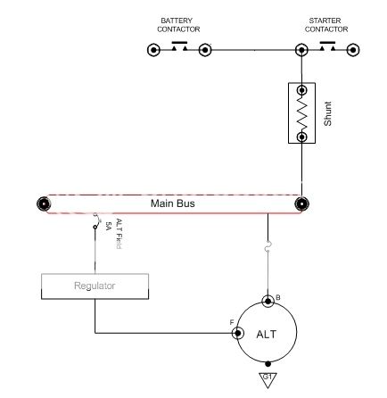
Most schematics (including Aeroelectric) have it shown as in the first diagram on the left - through the starter relay. Is there anything wrong with the diagram on the right wired directly through the bus? Seems like the electrons are routed through that circuit either way.

Would the ammeter be affected?

 
Electrically there is no difference in either drawing.

The rear battery of the 10 with the main contactor located at the battery favors the drawing to the right------but the buss is actually tied in at the starter contactor. Again, electrically the same, but only one wire needs to be brought forward from the rear.
 
Last edited:
It seems those are electrically the same to me. What ever is easier for wire routing. One comment though. Voltage tells you if the alternator is charging. Amps tell you the power. In this diagram if the alternator fails, you will lose your amp reading. And - it will vary depending on the charging of the battery, so guessing is in order as to the true demand amps by the non-charging (fixed) devices.

I chose to install the shunt in the wire to the busses. It will yield a stable amperage for the aircraft demand sans starting battery. The EFIS voltage reading tells me the "health" of the alternator. And it has an alarm. If the voltage drops, then it is measuring battery volts and the amps can still be managed by the pilot via turning things off until/unless needed.

Your desires, and instruments may vary, so this may not be for you.
 
The circuit on the right will weigh a little more because it requires two heavy wires connected to the main bus instead of one, a wire from the battery and one from the alternator. Either way will work though. Van's designed the RV-12 electrical system similar to the circuit on the right.
If you wire per the right-hand circuit, I suggest that the alternator fuse be relocated next to the battery contactor (but not in the starter circuit). The purpose of that fuse is to protect wires from excessive battery current if the alternator shorts out. The alternator output does not need to be fused because the alternator can not put out much more than its rating.
The ammeter will not be affected.
 
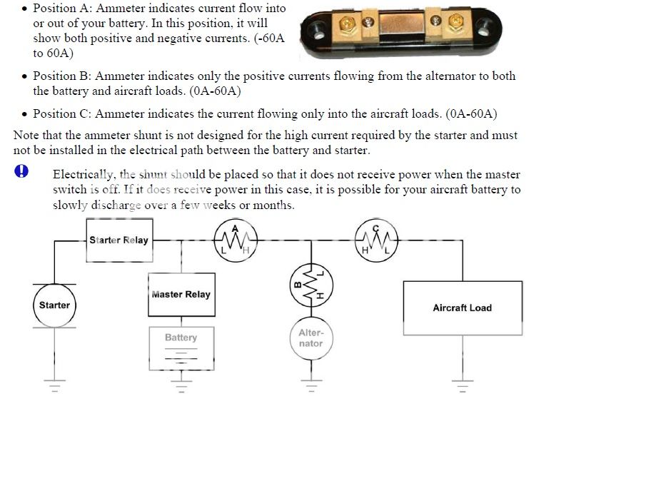
Dynon installation MANUAL on page 3-12 shows three possible shunt locations. I prefer location "B", same as in post #1 above.
It is a matter of personal preference. Whatever the shunt location, the pilot should understand what the ammeter is indicating.
A pilot who is not familiar with the electrical system could misinterpret an ammeter whose shunt is in location "C".
 
Electrically there is no difference in either drawing.

The rear battery of the 10 with the main contactor located at the battery favors the drawing to the right------but the buss is actually tied in at the starter contactor. Again, electrically the same, but only one wire needs to be brought forward from the rear.

Thanks Mike - I wasn't thinking about the wire size. That makes a difference when you consider the rear battery on the -10.
 
It seems those are electrically the same to me. What ever is easier for wire routing. One comment though. Voltage tells you if the alternator is charging. Amps tell you the power. In this diagram if the alternator fails, you will lose your amp reading. And - it will vary depending on the charging of the battery, so guessing is in order as to the true demand amps by the non-charging (fixed) devices.

I chose to install the shunt in the wire to the busses. It will yield a stable amperage for the aircraft demand sans starting battery. The EFIS voltage reading tells me the "health" of the alternator. And it has an alarm. If the voltage drops, then it is measuring battery volts and the amps can still be managed by the pilot via turning things off until/unless needed.

Your desires, and instruments may vary, so this may not be for you.

So you are suggesting more like this?

 
Last edited:
Dynon installation MANUAL on page 3-12 shows three possible shunt locations. I prefer location "B", same as in post #1 above.
It is a matter of personal preference. Whatever the shunt location, the pilot should understand what the ammeter is indicating.
A pilot who is not familiar with the electrical system could misinterpret an ammeter whose shunt is in location "C".

FWIW I used DYNON location "A" for my shunt HOWEVER, I then added a CS-02 Hall Effect Current Sensor at location "C". Location "A" amps tells me if the battery is charging or discharging while location "C" amps tells me how much current I am pulling which is great when you have an alternator failure and you need to minimize current draw. YMMV

:cool:
 
So you are suggesting more like this?


No, that will only be measuring battery charge amps as the alternator is connected directly to the loads. Look at the Dynon schematic. It has the battery there and is pretty clear. For me the "A" location is not relevant as I already have charging voltage, and if it is 14.2 I know the battery is charging. It may, however, give some insight to battery issues, so if I were using a Lithium starting battery my choice would be different. Some measure both A and C locations.

Just think about what you want the system to do, how it functions. In ordinary circumstances and if there is an alternator failure. Then, choose the schematic that addresses your most critical issues.
 
It's always hard to communicate the physical layout of a circuit in an electrical schematic. Example below:

circuit_diagram.jpg
 
It's always hard to communicate the physical layout of a circuit in an electrical schematic.

Vern you nailed it.

The Dynon schematic is even harder for me to understand because the picture looks like all 3 locations (A/B/C) are the same.

The definition of the Positions makes sense above, but the picture doesn't translate onto an airplane for me. The physical connection points, that is.


Both the drawing, and description seem right on to me.

Do a little mental exercise and trace the power flow from the battery before engine start, also from the alternator right after start, when the battery is sucking a lot of juice.

Then again with the battery still taking a small amount of juice, and finally after the battery is charged and taking virtually no juice.

You will see what each position of the shunt reads in the above conditions.
 
Pay special attention to the note about the shunt not being designed to handle the starter current. Best to install the shunt between the main bus and the alternator. We mention the same precaution with our systems when monitoring alternator current for the same reason.
 
For me the "A" location is not relevant as I already have charging voltage, and if it is 14.2 I know the battery is charging.

Not necessarily so. Unless your voltmeter is connected directly to the battery and independent of the cables, which I highly doubt, having a 14.2v indication doesn't tell you if your battery is charging or not. It just tells you the alternator is generating voltage. If you have a bad battery connection, bad master solenoid connection or either the positive or negative cable at the battery gets disconnected (maybe one vibrated loose while flying) you will still indicate 14.2v but no current will flow to the battery and it doesn't charge.

How much of a concern this is to you will determine which location you place your shunt. That is the beauty of experimental aviation, you get to make this kind of decision not some unknown factory person.

:cool:
 
Last edited:
So you are suggesting more like this?
That's the way I set mine up so the ammeter is telling me what's going into or out of the battery. Just after startup, I'll see maybe +10-15 Amps going into the battery while it recharges for a few minutes and then it settles down to a couple of amps. If the alternator fails (or I pull the ALT FLD circuit breaker), it reads negative according to whatever load I have at the moment. If I ever see it on the negative side, something is wrong. My B&C LR-1 regulator also has a low voltage warning light which actually works (ask me how I know).
 
Back
Top