What's new
Van's Air Force

Don't miss anything! Register now for full access to the definitive RV support community.

RV-7 cowling exit bump

Ok, I've got the Doug Gray instructions for determining TAS from GPS track and speeds. I may need a little help with the spreadsheet, my laptop doesn't have Excel and haven't been able to find a link to work yet.
Off topic, but I just saw this and thought i'd mention... If you don't have Excel, try OpenOffice from http://www.openoffice.org. It's free, and will read and write Excel and Word documents with ease.

The only place I have Excel on a computer now is at the office, where my company paid for it. All of my other computers use OpenOffice and I regularly move files back and forth between them. The only place i've had an issue is if the Excel file has embedded macros, sometimes they don't translate. But it's free to try it, in any case.

Also worth trying is Libre Office
http://www.libreoffice.org/

Which is a somewhat more open variant of Open Office. If one doesn't work, the other might.

Charlie
 
Finally back at it after vacations/work/family etc commitments.

From the previous posts I seemed to have picked up .8 knts and better cooling, I believe the cooling is better because the air is moving more efficiently through the exit. I believe the speed (perhaps its not/further test should show) is because the exit ramp/bump actually reduced the size of the outlet. How much I'm not for sure, I do know I had less room vertically to position the exhaust pipes with the ramp/bump in place.
Pic of the ramp/bump slightly narrowing the exit area, the seam between the bottom skin rivets and ramp/screws depicts the smaller area.
F74ABAE8-E1AE-4D8F-B837-0205378939C8_zps20iplphs.jpg

21CFFDB6-E8E9-4629-B8D9-0A3F06CBC8B4_zpsqnpai8bm.jpg
 
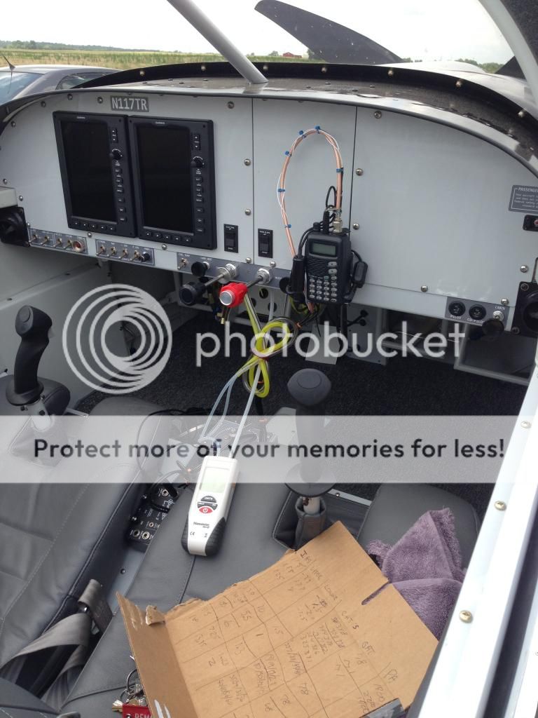
I finally received my Man-O-Meter and had a little time to play with it. The tubing is routed from the upper and lower piccolo tubes from the cowling and the other side of the Man-O-Meter is tapped into my static line. Boulevard Brewing promotes recycling of their boxes and since I forgot my kneeboard the donor Pale Ale box made a good scratch pad.
7AE86871-AE0B-4B40-8A10-5AFE17796622_zpsfzrj4om7.jpg


On this flight I was only after plenum pressure differentials, the readings on the Meter fluctuated about .40 and I tried to record the average. The Man-O-Meter does have an average function but I have to learn how to use it. I made 2 flights 4 hours apart at approximately 2000 Pressure Alt. and 78*F with plenum pressure differential measured between static pressure in in/H2O. Here's the rough averages:
115 knts IAS-upper plenum 7.5 In/H20-lower plenum 1.4 In/H2O
130 knts IAS-upper plenum 9 In/H2O-lower plenum 1.5 In/H2O
160 knts IAS-upper plenum 13.25 In/H2O-lower plenum 2 In/H2O

Significant differences from my water manometer in the cabin on the yard stick using cabin static pressures. Referencing this thread and graph http://www.vansairforce.com/community/showthread.php?t=114568&highlight=lycoming+cooling&page=4 post #33
my CHT's seemed to follow the graph pressure differentials.

My RV7 has an O-360 with dual EFII electronic ignition, standard Van's baffles and a Catto 3 blade. I believe my CHT's are higher because the electronic ignition completely burns the available fuel as well as possible advanced timing. I don't have a noticeable RPM rise while leaning from 200* ROP to peak EGT. I've got a very basic timing curve explanation but want a more complete explanation before commenting. At 80's*F OAT at 1000 Pressure Altitude CHT's have no issue staying under 390 above 130 IAS.

I also have 2 data sets at 100 IAS, 1 low power level at 100 IAS and 1 full power and 100 IAS climb. This is the realm of flight I'm most interested in cooling better. I started at 1800 Pressure Altitude and 78*F OAT.
Low power and level:
IAS 100-upper plenum 5.5 In/H2O-lower plenum 1 In/H2O
Full power climb:
IAS 100-upper plenum 6 In/H2O-lower plenum 1.3 In/H2O

Low power CHT's were average 320's, after the full power climb from 1800-5000 CHT's were 380/350/392/395 (1,2,3,4)

Not sure where this data leads me to next.....
-Seal lower cowling behind spinner/gear legs/vertical induction scoop/cowling seams.
-reshape cowling to "throttle" the exit
-cowl flap for low speed high power cooling
-just fly this one while I build the next one better!
 
"Low power CHT's were average 320's, after the full power climb from 1800-5000 CHT's were 380/350/392/395 (1,2,3,4)"

Hi Andy,
Those are perfect CHTs for a full power climb,
Robert
 
Decent temps, but I'm hoping for more. I had a 1.5 mile taxi and after a very quick runup all CHT's were 340-350. Shortly after takeoff at 1000 AGL I was approaching 390 on cylinders #3&4. If I would have continued my climb at 100-120 knts IAS they usually stabalize 405-410. The temps from the full power climb was after everything had cooled to the 320's at 100 knts IAS. The engine wasn't heat soaked, if it was temps would have been higher.

I need to do an oil change soon and am thinking about adding an additional piccolo tube in the lower cowling exit area for another data point.

I'm just muddling my way through this and appreciate any help.

My CHT's seem to follow the lycoming cooling air requirements chart (https://www.google.com/search?q=lyc...owthread.php%3Ft%3D107109%26page%3D5;776;554) best I can tell at 100 knts IAS. At 100 knts IAS, pressure alt 1800 and 78*F my upper/lower differential is about 4.5 in h2o. Interpolating the chart yields close to the 410*F that I'm used to seeing on cylinders #3/4 after extended climbs.
At 160 knts IAS, pressure alt 1800 and 78*F my pressure differential is about 11.25 in h2o. Hard to interpolate the chart, but seems to be consistent with my CHT's of 360-380.

As I understand it the greater the pressure differential the better the cooling, with the lower cowling pressures of 1-2 in h2o there's not a lot of pressure to lose in this area.
-If I work at pressurizing the lower cowling then I will gain lower cowling pressure which will shrink my pressure differential and CHT's will rise. Or will the pressures around the cylinders where I'm measuring pressure stay about the same and the exit pressure will change?
-Perhaps the existing "cattle chute" exit causes a turbulent flow of exit air which helps to inefficiently pressurize the lower cowl, a throttled smooth/laminar flow exit will move more air while providing the same pressures?
-For 100 knts IAS and below cooling if I add a cowl flap and bring the lower cowling pressure close to 0 I should gain about 1 in h2o of differential and 10-20 *F lower CHT's?

Thanks,
Andy
 
Last edited:
. . . I believe my CHT's are higher because the electronic ignition completely burns the available fuel as well as possible advanced timing. . . .!

"completely burns" nah - - it is the advance(if anything), it begins combustion sooner and burns more of the mixture before top center, so this means a higher average temperature in the chamber resulting in more heat transfer and CHT.

. . .Or will the pressures around the cylinders where I'm measuring pressure stay about the same and the exit pressure will change?

Andy

Air is funny - in a nozzle if the throat is choked, it is where the max velocity is reaches or approaches mach 1. At that point the back pressure does not affect up stream much, if at all. Your case, our case, is that if the lower plenum pressure is changed it probably will effect a change in the upstream pressure, but it depends. Think about the different effects, air to the plenum, air through the fins, and then collection and air out the exit. Choke the exit and you will probably see each pressure rise. If you are looking for cooling, then the flow across the engine is the key - and management of the flow along that path.

Someone else will have to address the temperature absolutes of your CHT.

Great Data - thanks for sharing it, I will be gathering similar data and will replicate your/Dan's tube configuration.

oh - is a Man-O-Meter sexist? :D

Edit: I just started checking to see what the dynamic pressure is at 100kt - 1800 msl. It yields only about 4.3 in-H2O pressure. If you are really getting 5-6 then that is all you could expect for cooling. I would like to hear others discussion about this because we should not expect to require 5 in-h2o and generate that at such a low airspeed. What am I missing?
Correction: At 100kt, 1800 ft, the dynamic pressure is 6.13 in-h2o - Dan (see below) is correct. I fat fingered and did not get the conversion from knots to get/sec correct.
http://www.engineeringtoolbox.com/dynamic-pressure-d_1037.html this is the pressure calculator.
 
Last edited:
"completely burns" nah - - it is the advance(if anything), it begins combustion sooner and burns more of the mixture before top center, so this means a higher average temperature in the chamber resulting in more heat transfer and CHT.

+1

Your case, our case, is that if the lower plenum pressure is changed it probably will effect a change in the upstream pressure, but it depends.

It will, no question.

Edit: I just started checking to see what the dynamic pressure is at 100kt - 1800 msl. It yields only about 4.3 in-H2O pressure.

Dunno about the online calculator. Plug this easy equation into Excel and you'll have a handy dandy desktop Max Q calculator. Only caveat is that it assume Standard Day conditions. Keep in mind that you'll never see Max Q in an upper plenum measurement, unless of course you fully plug the cowl exit. Or get fooled by prop blast.

ivd8nt.jpg
 
Last edited:
Andy...quick comparison, as i happen to have done the same test

Andy:
Low power and level:
IAS 100-upper 5.5 lower 1 delta 4.5

Full power climb:
IAS 100-upper 6 lower 1.3 delta 4.7

Dan:
Low power and level:
IAS 100-upper 6 lower 2.5 delta 3.5

Full power climb:
IAS 100-upper 9 lower 3.75 delta 5.25

Conditions were 3500 ft PA and 53F. These numbers were taken with a smaller than stock exit on my RV-8, thus the increased lower cowl pressures. It's probably the reason for the extra 0.5 upper cowl pressure in the low power case, as compared to yours. At full power, 9" upper is probably due to the lower blade pitch of my constant speed. The additional pressure helps cooling (note the delta), but given two otherwise equal engines, CHTs may not be much different. The constant speed engine would be at a higher RPM, more power, more cooling requirement.

Nice work, keep it up!
 
Last edited:
Back
Top