
Van's Air Force
You are using an out of date browser. It may not display this or other websites correctly.
You should upgrade or use an alternative browser.
You should upgrade or use an alternative browser.
Anti Splat Aero cowl flap
- Thread starter ALagonia
- Start date

swisseagle
Well Known Member
Only effective till Vy ...
Hello RV-7A, IO-320, a good 10+ deg. cooler. It is only effective during climb out. On speeds higher than Vy (93kt in my case) there is nearly no effect and cylinder cools better due to airspeed. Anyway, after about 2000ft AGL, changing to cruise-climb speed 100-110kt, then closing the cowl flap.
Only on one side, one installed.
I don't use it for cruise or easy climb, but for a max performance climb during the summer it certainly helps keep my CHT's reasonable - I'm going to say 15-20 degrees cooler on the CHT's and my oil temps maybe 10.
Hello RV-7A, IO-320, a good 10+ deg. cooler. It is only effective during climb out. On speeds higher than Vy (93kt in my case) there is nearly no effect and cylinder cools better due to airspeed. Anyway, after about 2000ft AGL, changing to cruise-climb speed 100-110kt, then closing the cowl flap.
Only on one side, one installed.
I have two installed in my -7 with a new O-360. I wasn't able to keep the CHT's bellow 420 on take off even with 115 knots IAS. With the two cowls open now my CHT's stay around 400 and once the speed picks up they drop down to under 350. They don't seem to have much effect on my oil temps that are usually around 180 anyway. So I have about 20 degrees drop with the cowls.
?Two on each side of your cowling??I put two on each side of the lower cowl of my RV-7. It solved my oil temp problems!
I only have one cylinder that is higher than the others. I?m thinking maybe one cowl flap rather than trimming my lower cowl. That cowl flap on the left side since it is #4 CHT that is high.
“Two on each side of your cowling?”
I only have one cylinder that is higher than the others. I’m thinking maybe one cowl flap rather than trimming my lower cowl. That cowl flap on the left side since it is #4 CHT that is high.
I don't know if it would really matter where you put it exactly. I had a 260 Comanche with the LoPristi cowling that worked great at cooling the 260hp Lycoming. It used a single cowl flap located on the left side just below the wing root. Temps did not shift left or right with cowl flap use.
+1
My number 3 cylinder was getting a little above 400 degrees on hot days. So, I just put one flap on the right side. I get a drop of about 5 degrees F. I find that very helpful on climb out on hot days and in level cruise when heavily loaded at high altitude in the summer. I love having it when crossing mountains.
The effectiveness of the flap is easy to estimate in cruise since you can open and close it and watch the effect on the cht's. The 5 degree difference holds true for me in level flight. The installation is surpringly easy. I agree with Cduster. If you only install one, it probably doesn't matter which side you put it on. John
Last edited:
rockbottom
Active Member
anchor nuts
I installed two doors on my 8 with anchor nuts riveted to the perimeter of the door flanges in case I decide to remove them later on. I have had no issues with cooling but wanted to experiment with reducing the size of the exhaust outlet in an attempt to minimize frontal drag.
Because of the shape of the bottom of the cowl where the doors are mounted, I added a thin layer of micro reinforced with fiberglass on the outer surface of the doors to match the curvature of the cowl.
Using anchor nuts mounted on the flange of the doors required building up a layer of micro around the door opening on the inside of the cowl to provide a flat surface for the door flanges to rest on. I haven't had a chance to modify the cowl yet as desired, and consequently, have not had to use the doors very often to enhance cooling.
J Baker
RV8/IO-375/Hartzell CS prop/dual pmags
I should also add that my CHTs (#3 and 4) are only "high" on take-off during the summer on hot and humid days at sea level. Once in cruise, the CHTs are around 370 (cooler in winter) at roughly 2,000 depending on power setting - I usually have no reason to climb any higher. One issue that I have not investigated is fuel flow because last time I checked, it was 15.5gph on take off, which is low. The other is timing - I have SDS on one side, and I've been advised to retard the remaining mag from 25 to 23. Note that the "high" CHT was "high" before the installation of electronic ignition. I suspect that airflow through the cowling is not the main reason for my "high" CHTs, and why I haven't experienced a dramatic reduction when using the cowl flap.
Adding a bit more detail, the FF on takeoff for the past two years varies between 14.9-15.9 GPH, which apparently is low. Since the airplane is in the middle of its condition inspection, I'm going to recheck the Red Cube to make sure it is accurate, and if it is, re-jet the carb. Have to read up on that procedure.
As for the cowl flap not functioning, I hooked it up to independent power, and it did not work. Subsequently I removed the actuator, undid the four cover tiny screws and discovered that the power lead negative side was broken at the flexible ribbon attached to the motor contacts. Not sure if I'll be able to repair it. Also not sure what broke the lead, maybe flapping around in the turbulence of the lower cowl? Bad decowling procedure? IDK. Probably going to plop some RTV at the point where the wires enter the actuator shell, and cable tie the wire to the actuator body if I decide to reinstall.
As for the cowl flap not functioning, I hooked it up to independent power, and it did not work. Subsequently I removed the actuator, undid the four cover tiny screws and discovered that the power lead negative side was broken at the flexible ribbon attached to the motor contacts. Not sure if I'll be able to repair it. Also not sure what broke the lead, maybe flapping around in the turbulence of the lower cowl? Bad decowling procedure? IDK. Probably going to plop some RTV at the point where the wires enter the actuator shell, and cable tie the wire to the actuator body if I decide to reinstall.
Captain Avgas
Well Known Member
Proceed with caution.
AntiSplat have some good products but I have personal reservations about their electric cowl flap. These are my thoughts.
1. This device is installed in the lower cowl, generally in the vicinity of exhaust pipes that will be generating a lot of heat.
2. It is doubtful that the electric motor supplied with this device is capable of operating continuously in a high temperature environment.
3. The bottom of the cowl is an area where fuel for an engine fire can accumulate....consider oil dripping from the engine, or consider avgas dripping down from over priming. This is definitely not a location where you want to have an ignition source created by a faulty electric device.
Anyway, that’s my thoughts, bearing in mind that I tend to be pretty conservative about FWF matters.
Apart from the above I suspect that most of the overheating problems reported in Lycoming powered RVs are due to poor workmanship, particularly in the baffles, and that cowl vents/flaps are just a quick and dirty fix.
Last edited:
I installed a pair of Anti-Splat’s cowl flaps just last month. I was replacing a pair of 4”x5” louvers, and was hoping to reduce my climb CHT to below 400 F in the 100 degree Texas summer heat. To that end it was successful.
Installation was a snap, though I puzzled over how best to mount them. My RV-6 uses the older, thinner fiberglass cowl, so I figured I’d need to fill the resulting gap between the flange and the cowl somehow. In the end, I realized that because of the flange, there was no way they were going to fall out, so my installation became pretty simplified. I simply cut a hole with a dremel tool and secured the assembly with a flush pull rivet in each corner. To get the cowl flap door to lie flush with the outer skin, I had to stack some washers under the flange. The gap between the mounting flange and the cowl was sealed from the inside using pieces of metalized peel & stick duct tape. Nothing shows from the outside. It worked like a champ. I also used the tape to relieve the strain on the thin wiring where it enters the servo, as well as to secure and shield the wire as it runs up the inside of the cowling. Near the top of the lower cowl, I added an inline fuse in the positive lead, and a quick disconnect spade on the negative. This allows for easy disconnection of the wiring when removing the lower cowl. While I was at it, I added a couple of strips of the shiny tape to the sides of the servo motor to help reflect heat. I also added one of Anti-Splat’s heat shields to the left exhaust pipe to keep exhaust heat away from the unit. The right side didn’t need it because the heater muff served the same purpose.
One change I intend to make. . . The switch Allan provides is a two position (open/closed) type, so the flap can only be fully open, or fully closed. I want to be able to position the flap in a trailing position to provide some additional cooling with less drag when cruising at high power settings in hot conditions. Wiring in a momentary on/off/on switch should do the trick.
Overall, I’m very happy with the product and the installation.
-John
Last edited:
I installed a pair of Anti-Splat?s cowl flaps just last month. I was replacing a pair of 4?x5? louvers, and was hoping to reduce my climb CHT to below 400 F in the 100 degree Texas summer heat. To that end it was successful.
Installation was a snap, though I puzzled over how best to mount them. My RV-6 uses the older, thinner fiberglass cowl, so I figured I?d need to fill the resulting gap between the flange and the cowl somehow. In the end, I realized that because of the flange, there was no way they were going to fall out, so my installation became pretty simplified. I simply cut a hole with a dremel tool and secured the assembly with a flush pull rivet in each corner. To get the cowl flap door to lie flush with the outer skin, I had to stack some washers under the flange. The gap between the mounting flange and the cowl was sealed using pieces of metalized peel & stick duct tape. It worked like a champ. I also used the tape to relieve the strain on the thin wiring where it enters the servo, as well as to secure and shield the wire as it runs up the inside of the cowling. Near the top of the lower cowl, I added an inline fuse in the positive lead, and a quick disconnect spade on the negative. This allows for easy disconnection of the wiring when removing the lower cowl. While I was at it, I added a couple of strips of the shiny tape to the sides of the servo motor to help reflect heat. I also added one of Anti-Splat?s heat shields to the left exhaust pipe to keep exhaust heat away from the unit. The right side didn?t need it because the heater muff served the same purpose.
One change I intend to make. . . The switch Allan provides is a two position (open/closed) type, so the flap can only be fully open, or fully closed. I want to be able to position the flap in a trailing position to provide some additional cooling with less drag when cruising at high power settings in hot conditions. Wiring in a momentary on/off/on switch should do the trick.
Overall, I?m very happy with the product and the installation.
-John
How much reduction in CHT's did you see?
PerfTech
Well Known Member
.AntiSplat have some good products but I have personal reservations about their electric cowl flap. These are my thoughts.
1. This device is installed in the lower cowl, generally in the vicinity of exhaust pipes that will be generating a lot of heat.
2. It is doubtful that the electric motor supplied with this device is capable of operating continuously in a high temperature environment.
3. The bottom of the cowl is an area where fuel for an engine fire can accumulate....consider oil dripping from the engine, or consider avgas dripping down from over priming. This is definitely not a location where you want to have an ignition source created by a faulty electric device.
Anyway, that?s my thoughts, bearing in mind that I tend to be pretty conservative about FWF matters.
Apart from the above I suspect that most of the overheating problems reported in Lycoming powered RVs are due to poor workmanship, particularly in the baffles, and that cowl vents/flaps are just a quick and dirty fix.
?. I think perhaps I should throw a few thoughts out as well for consideration, as I do have some skin in this game!
I was a bit concerned as were some others, in the beginning with the possibility of temperature degrading or damaging
the electronic actuators. To the contrary, this was not the case, with over 5K units out there and six years in service.
We have not seen one failure attributable to heat! We have had a few failures due to the original aluminum hinges
cracking ( all is the first 100 units). We have not had even one since we went to very heavy stainless hinges. We have
seen a few failures where the wires were pulled loose internally from not being restrained properly, or not being
disconnected before removing the lower cowl. The actuators are not a very likely ignition source for several reasons.
They are completely sealed, they are internally fused, They pull only .1 amp, we advise installation of .5 amp fuse
per two units to protect the wires as well. If you dead short the wires to ground the fuse will pop prior to wire heating.
Also worth mentioning is the fact they are only in use for 3 or 4 seconds per cycle. Considering all the aforementioned,
this product is hardly a risky ignition source. I can think of several items that offer far more potential for this type of
problem on all these aircraft.
? We see several aircraft weekly at our facility and on occasion we do see some poor workmanship, but its not the norm.
Most are average or above and some are fantastic. The RVs have very tight engine compartments with lower air flow
than most GA aircraft. They generally produce optimum rated output and most can benefit from added convenience of
the EZ Cool Flaps. This is nothing new or groundbreaking, as almost without exception GA aircraft manufacturers elect
to equip their aircraft with cooling flaps. If they weren't needed or desirable to have they would have elected to save
the manufacturing costs. Just my thoughts. Thanks, Allan..

They work as advertised. As for them being a band aid for poor construction, etc. that's not on subject and honestly a very presumptive assessment. I fly in conditions from 20 to 105 F, airports at 10 ft MSL to 9,900-ft. The flexibility these devices offer is exactly what I needed. My engine cooling is tight and effective. I have my timing at an optimum point for power and temperature control. And last, I will not operate at >400 CHT. With these cowl flaps, I do not have to stair step my climb anywhere. They offer me 8-10 deg improvement on my hottest CHT. But you pay with a 3-4 kts of drag. For this reason, I rarely use them in cruise. But there are some scenarios where it's nice to be able to crack them open to knock off a couple of degrees CHT rather than upset the mixture with a nicely balanced LOP cruise condition.
Mine (two) have been installed 2,3 years now, in the typical location in the bottom of the cowl on each side of the exhaust. Yes, an articulated cowl exhaust augmenter arrangement would likely serve the same cooling benefits with less drag. But the ASA cowl flap option provided the benefits I needed at the time.
Mine (two) have been installed 2,3 years now, in the typical location in the bottom of the cowl on each side of the exhaust. Yes, an articulated cowl exhaust augmenter arrangement would likely serve the same cooling benefits with less drag. But the ASA cowl flap option provided the benefits I needed at the time.
Last edited:
Captain Avgas
I think your post of something for which you have no first hand knowledge is pretty lame. You make a number of assumptions that are wrong. Perhaps you might do more research and talk to folks who have flaps installed before offering an uneducated opinion.
I think your post of something for which you have no first hand knowledge is pretty lame. You make a number of assumptions that are wrong. Perhaps you might do more research and talk to folks who have flaps installed before offering an uneducated opinion.
Easy now gents. Blame me. Bob is probably thinking of my posts regarding the temperature sensitivity of that particular actuator, as I did detect some increasing internal freeplay when using that particular brand to operate a variable exit. My lower cowl air temperature is higher than average, but the actuator location is fully shielded from radiant heat exposure, so it's not an unreasonable concern. Allen says he has sold 5000 of them without a heat related failure. At two per airplane, that would be about 1/4 of the entire RV fleet. Interesting dichotomy, not that it matters. They seem to be reliable enough, and I think he is supplying a model one size larger than I used.
Will open cowl flaps work, as in lower CHT? Of course they will, as they increase mass flow...assuming that mass is actually flowing through the cylinder fins, not just bypassing the engine via crappy seals.
No, it's not.
Best power is typically found in the BSFC range between 0.5 and 0.55 lbs per horsepower per hour. The quick math is easy. If we assume 0.5 BSFC (the bottom of the range) just compare fuel flow x 12 with expected HP for the altitude. Your signature says you have an O-360 and location says you're near sea level, so let's be generous and say you're making 180 hp. 14.9 x 12 = 178.8, while 15.9 x 12 = 191. You have plenty of fuel.
Still don't believe? Minimum fuel flow for best power, for the 390 per the Lycoming manual, is 105 lbs for 210 rated HP, or 0.5 BSFC. That's 17.5 GPH, exactly what I indicate at full throttle and 200 MSL. I then lean in the climb to keep EGT where it was at liftoff, all the way up. Lots of us do.
Can you make it run cooler by dumping more fuel in it? Yep. I have dyno charts which say you can run it out to around 0.6 and drop CHT as much as 35F. Power is down, and it's dirty, and it's expensive, but it will work.
Will open cowl flaps work, as in lower CHT? Of course they will, as they increase mass flow...assuming that mass is actually flowing through the cylinder fins, not just bypassing the engine via crappy seals.
Adding a bit more detail, the FF on takeoff for the past two years varies between 14.9-15.9 GPH, which apparently is low.
No, it's not.
Best power is typically found in the BSFC range between 0.5 and 0.55 lbs per horsepower per hour. The quick math is easy. If we assume 0.5 BSFC (the bottom of the range) just compare fuel flow x 12 with expected HP for the altitude. Your signature says you have an O-360 and location says you're near sea level, so let's be generous and say you're making 180 hp. 14.9 x 12 = 178.8, while 15.9 x 12 = 191. You have plenty of fuel.
Still don't believe? Minimum fuel flow for best power, for the 390 per the Lycoming manual, is 105 lbs for 210 rated HP, or 0.5 BSFC. That's 17.5 GPH, exactly what I indicate at full throttle and 200 MSL. I then lean in the climb to keep EGT where it was at liftoff, all the way up. Lots of us do.
Can you make it run cooler by dumping more fuel in it? Yep. I have dyno charts which say you can run it out to around 0.6 and drop CHT as much as 35F. Power is down, and it's dirty, and it's expensive, but it will work.
PerfTech
Well Known Member
.Easy now gents. Blame me. Bob is probably thinking of my posts regarding the temperature sensitivity of that particular actuator, as I did detect some increasing internal freeplay when using that particular brand to operate a variable exit. My lower cowl air temperature is higher than average, but the actuator location is fully shielded from radiant heat exposure, so it's not an unreasonable concern. Allen says he has sold 5000 of them without a heat related failure. At two per airplane, that would be about 1/4 of the entire RV fleet. Interesting dichotomy, not that it matters. They seem to be reliable enough, and I think he is supplying a model one size larger than I used.
??..Thanks Dan for the comments, and it looks like I need to clarify the over 5K
units in use. We sell a lot of the Easy Cool Flaps to all experimental aircraft
via Spruce, as well as many to the automotive industry for under hood use.
The "over 5K includes all actuators we have purchased from that supplier".
Sorry for the confusion guys. Thanks, Allan
Captain Avgas
Well Known Member
Easy now gents. Blame me. Bob is probably thinking of my posts regarding the temperature sensitivity of that particular actuator, as I did detect some increasing internal freeplay when using that particular brand to operate a variable exit.
Quite correct Dan. I recall that you ultimately ditched your Firgelli L12 Actuator after only about 10 to 15 hours of operation at temperatures of 160 - 200 F due to excessive play in the mechanism. You stated at the time that you considered that your incowl temps could in fact reach 230 F. In fact the Firgelli L12 spec sheet calls for a max operating temp of only 122 F. You also stated at the time that the Ray Allen actuators have a ?sorta maximum rating of 180 F?. The Ray Allen actuator spec sheet does not have a max operating temperature but you probably got that information from their FAQ page which states that the nylon components are likely to deteriorate above 180 F. As far as the Ray Allen actuator is concerned the following statement from Ray Allen is relevant: ?We know of our servos that are used successfully inside cowlings, but we are hesitant to recommend it. Try to keep the servos in a ventilated location under the cowl away from exhaust pipes, or better yet, behind the firewall?.
I don?t think it would come as any surprise to anyone who had actually done any real research on this matter that these cheap actuators with relatively low operating temperatures are not going to like being in the elevated temperatures adjacent to exhaust pipes.
But hey, this is the Experimental Category so builders can do whatever they want. I?m just raising the matter so people can be a little bit more informed about the potential pitfall of locating electrical devices with specified low operating temperatures in high temperature locations, particularly when those locations may be subject to the accumulation of flammable liquids.
bkc3921
Well Known Member
My experience with the Antisplat Cowl Flap install and results
I just finished my install, and have been using it for about 2 weeks. I'm used to a 400 degree Vy step climb on a 90 degree Midwestern day, and now its comfortably around 380..so I am very pleased with the result...Now to the install.
I had an issue with the LED indicator emitting more heat than I though was normal. I spoke to Allan a couple of times, and as always he is quick to respond. Through more troubleshooting than you would care to know, we never did really come to a conclusion. I simply began to realize that the amount of heat the LED gave off was apparently "normal"..It has not been an issue to date.
I truly support Allan and his company...I believe many of his products are useful, and everyone is free to use them if they so desire...if I have any (minor) complaints, it is something Allan said on his install video. He said you could probably do this "in a couple of hours".... Yeah, right. If my grandma had wheels, she would be a wagon. (Sorry, Allan!) Just wiring that 6-lug mini switch takes longer than that. Choosing the correct flap location, making sure that the flap doesn't interfere with existing structures, routing wires, mounting the switch to the panel AND a power source, installing an in-line 0.5 fuse, CAREFULLY cutting and sanding the mounting hole for the flap, epoxy and cowl curvature shimming work, and any necessary painting takes FAR, FAR longer than "a couple of hours".....
Having said that, I'm still glad I did the install, and I'm enjoying the lower temperatures. Thanks Allan!...
I just finished my install, and have been using it for about 2 weeks. I'm used to a 400 degree Vy step climb on a 90 degree Midwestern day, and now its comfortably around 380..so I am very pleased with the result...Now to the install.
I had an issue with the LED indicator emitting more heat than I though was normal. I spoke to Allan a couple of times, and as always he is quick to respond. Through more troubleshooting than you would care to know, we never did really come to a conclusion. I simply began to realize that the amount of heat the LED gave off was apparently "normal"..It has not been an issue to date.
I truly support Allan and his company...I believe many of his products are useful, and everyone is free to use them if they so desire...if I have any (minor) complaints, it is something Allan said on his install video. He said you could probably do this "in a couple of hours"....
Yeah, right. If my grandma had wheels, she would be a wagon. (Sorry, Allan!) Just wiring that 6-lug mini switch takes longer than that. Choosing the correct flap location, making sure that the flap doesn't interfere with existing structures, routing wires, mounting the switch to the panel AND a power source, installing an in-line 0.5 fuse, CAREFULLY cutting and sanding the mounting hole for the flap, epoxy and cowl curvature shimming work, and any necessary painting takes FAR, FAR longer than "a couple of hours".....Having said that, I'm still glad I did the install, and I'm enjoying the lower temperatures. Thanks Allan!...
Last edited:
pecanflyboy
Well Known Member
Single unit position
My RV-6 cowl is tight on the sides of the exhaust pipes. Has anyone installed this unit in the center of the cowl, between the exhaust pipes, in the most aft position? This would seem to have the same effect as trimming the exit area to make it larger.
My RV-6 cowl is tight on the sides of the exhaust pipes. Has anyone installed this unit in the center of the cowl, between the exhaust pipes, in the most aft position? This would seem to have the same effect as trimming the exit area to make it larger.
Last edited:
pecanflyboy
Well Known Member
Installed the Anti Splat EZ Cool Cowl Flap on my RV6 Sam James cowl. This is a 10:1 IO-360 with a CS prop.
Flight test on a 93°F day, after a touch and go at 700' MSL with a 120KIAS climb to 8000', 25 squared until WOT, Full Rich. With the cowl flap open, oil temps reduced 7°F, CHT's reduced 15°F, and I lost 2 knots at 8000'.
I positioned the cowl flap between the exhaust pipes, centered on the cowling exit, as far aft as possible (about 1" from the aft edge of the cowling).
The kit is nice quality and well designed, although there could be some improvements. The inside corners of the flap box were square with a slight over cut. I'd suggest these be radiused to avoid cracking. I replaced the wiring with ETFE Mil-spec wiring, as the supplied wire was a bit fragile. I also replaced the plug with a locking plug.
Installation was straight forward. I had to build up the cowling with epoxy microbead so that the flap fit flush when closed. Instead using the LED, I wired a discrete pin to my G3X with a "Cowl Flaps" annunciation.
I'm please with the modification as it is performing as expected.
$$
Installation was straight forward. I had to build up the cowling with epoxy microbead so that the flap fit flush when closed. Instead using the LED, I wired a discrete pin to my G3X with a "Cowl Flaps" annunciation.
$$
Did you need a resistor inline to the GAD 27/GEA 24 (whatever you used for the discrete) or were you able to just run the high or low to the discrete pin?
pecanflyboy
Well Known Member
Did you need a resistor inline to the GAD 27/GEA 24 (whatever you used for the discrete) or were you able to just run the high or low to the discrete pin?
I have the GSU73. I only wanted a "COWL FLAP" annunciation when the flap was open. So, I took a discrete pin from the GSU73 to the pin on the switch that grounded in the cowl flap "OPEN" position. I configured this to a low activation, so no need to use a resistor. It's just a switch position indicator.
Another satisfied customer
I realize this is a long running thread but I just wanted to voice my experience with Anti Splat's cowl flap.
When my 6A was finished at I started to fly off the hours, I had extremely high engine temps which even forced me to cancel flights. I went back and rebuilt the baffles and baffle seals and resealed, which helped, but not much.
I finally bit the bullet and bought two flaps and installed them in the lower cowl per the plans. Took a bit of work but it was really worth it. The flaps work so far without any issues. CHTs went down considerably and I was able to continue the fly off.
We are already hitting 95 degrees by midday and this has been a cool spring and early summer. The cowl flaps make a difference.
There have been several 6 series planes built out in in this area (west Texas) and every one had major issues with hi engine temps and all resorted to one fix or another, like cutting up the cowl and putting in bigger coolers and ugly louvers on the bottom of the cowl. This was before the Anti-Splat was available. The cowl flaps are the solution as far as I am concerned and I am very satisfied with the product.
Dave A.
scsmith
Well Known Member
I received my ASA cowl flap recently. The frame is made to fit into a cowl that is about 1/4" thick. I planned to install mine in the middle of the "coal shovel" exit channel, which is not honeycomb sandwich. It is about 1/16" or less thick. So I was wondering why oh why did Allan make the frame drop in so deep? Whose cowl is so thick? So now I know. Some folks install the cowl flap in the honeycomb area on either side of the coal shovel exit.
In the honeycomb areas, the cowl is apparently about 3/16" thick? so it apparently still takes a bit of shim under it.

Since I was mounting in much thinner material, rather than have a big layer of build-up on the inside to get the flap flush on the outside, I made a new frame that is just 0.063" thick, and re-assembled the flap on that frame. A spacer was needed under one of the actuation linkage anchor points to keep the actuation geometry working right. It is a fairly clever actuation linkage. With the thin frame, the cowl flap surface was slightly below the cowl surface, so I slathered a layer of epoxy/microballoons over it and then sanded it completely flush. The area where it is installed is not flat, it is convex, so it was going to take some filler to contour in any case.
A couple of other install details:
While I was making the new frame, I noticed that the pivot points were assembled with AN bolts and low profile (AN364) elastic stop nuts. This type of application where the parts are moving and the bolt is not clamped down tight really should have a castle nut with a cotter pin. A minor detail? It is just a cowl flap, after all.
But to reassemble the linkage on the new frame, I had to take all the bolts out of the linkage, and I was surprised to find that the AN bolts were all too short, so that the unthreaded portion (the shank) was not long enough to extend through all the moving parts. At each point in the linkage where two pieces are moving on the pivot bolt, one of the two pieces was entirely moving on the threaded portion of the bolt!

Considering that this linkage will see one full cycle per flight (open for take-off, close for cruise, open again for landing) and in an environment with some soot/grime, this seems really poor to me! The linkage parts are made elegantly lean, meaning not a generous amount of edge clearance on the pivot holes, and then, here they are with a high-wear situation with one of the parts turning on the threads of the pivot bolt! It won't be long before those holes are all worn oval, the flap will not close all the way because the nice linkage will have slop at all the joints from wear. Sorry Allan, but I really think you can do better! I replaced all the AN bolts with proper-length clevis bolts so that the parts are turning on the unthreaded shank, then a washer, a castle nut, and a cotter pin.
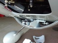
Finally, I totally understand the logic of having the unit all self-contained, with the actuator installed directly on the cowl flap frame. This is desirable from both a manufacturing standpoint and an installation standpoint, where a single drop-in unit really makes it tidy, fast, simple. - BUT -- the actuator itself is positioned right in the area where the flow is accelerating and trying to rush out through the open cowl flap. The actuator constitutes a blockage of over 15% of the net flow area out of the cowl flap! The aerodynamicist in me just couldn't stand for that, so I added a 5" extension shaft on the actuator, and relocated the actuator upstream, where the velocities are slower, both with the flap closed, and with the flap open. This is a fussy detail I admit, and as I said, I understand the logic of having a self-contained unit. But I like this better.

Look close you can see the castle nuts on the clevis (pivot) bolts. Note also that the bolt that holds the actuator shaft to the linkage is a 8-32 shoulder bolt that tightens down tight, so an elastic lock nut is acceptable there. The extension shaft is a thick-walled 3/8" aluminum tube, threaded at both ends for 8mm x 1.25mm. The actuator shaft is threaded similarly for the black plastic end fitting, which I just moved to the end of the extension tube. The coupling between the original actuator shaft and the extension is just a 1" length of 8mm x 1.25mm bolt, drilled hollow to save a little weight. I ended up needing 2 0.2 mm shim washers between the tubes to get the clocking right, so the end fitting lined up with the linkage. You can also see that I incorporated a radiant-heat shield in the mounting bracket for the actuator, since the whole thing is nestled up among the exhaust pipes. Allan does recommend putting heat shields on the exhaust pipes, that will work too. But this seems tidy.
In the honeycomb areas, the cowl is apparently about 3/16" thick? so it apparently still takes a bit of shim under it.
Since I was mounting in much thinner material, rather than have a big layer of build-up on the inside to get the flap flush on the outside, I made a new frame that is just 0.063" thick, and re-assembled the flap on that frame. A spacer was needed under one of the actuation linkage anchor points to keep the actuation geometry working right. It is a fairly clever actuation linkage. With the thin frame, the cowl flap surface was slightly below the cowl surface, so I slathered a layer of epoxy/microballoons over it and then sanded it completely flush. The area where it is installed is not flat, it is convex, so it was going to take some filler to contour in any case.
A couple of other install details:
While I was making the new frame, I noticed that the pivot points were assembled with AN bolts and low profile (AN364) elastic stop nuts. This type of application where the parts are moving and the bolt is not clamped down tight really should have a castle nut with a cotter pin. A minor detail? It is just a cowl flap, after all.
But to reassemble the linkage on the new frame, I had to take all the bolts out of the linkage, and I was surprised to find that the AN bolts were all too short, so that the unthreaded portion (the shank) was not long enough to extend through all the moving parts. At each point in the linkage where two pieces are moving on the pivot bolt, one of the two pieces was entirely moving on the threaded portion of the bolt!
Considering that this linkage will see one full cycle per flight (open for take-off, close for cruise, open again for landing) and in an environment with some soot/grime, this seems really poor to me! The linkage parts are made elegantly lean, meaning not a generous amount of edge clearance on the pivot holes, and then, here they are with a high-wear situation with one of the parts turning on the threads of the pivot bolt! It won't be long before those holes are all worn oval, the flap will not close all the way because the nice linkage will have slop at all the joints from wear. Sorry Allan, but I really think you can do better! I replaced all the AN bolts with proper-length clevis bolts so that the parts are turning on the unthreaded shank, then a washer, a castle nut, and a cotter pin.
Finally, I totally understand the logic of having the unit all self-contained, with the actuator installed directly on the cowl flap frame. This is desirable from both a manufacturing standpoint and an installation standpoint, where a single drop-in unit really makes it tidy, fast, simple. - BUT -- the actuator itself is positioned right in the area where the flow is accelerating and trying to rush out through the open cowl flap. The actuator constitutes a blockage of over 15% of the net flow area out of the cowl flap! The aerodynamicist in me just couldn't stand for that, so I added a 5" extension shaft on the actuator, and relocated the actuator upstream, where the velocities are slower, both with the flap closed, and with the flap open. This is a fussy detail I admit, and as I said, I understand the logic of having a self-contained unit. But I like this better.
Look close you can see the castle nuts on the clevis (pivot) bolts. Note also that the bolt that holds the actuator shaft to the linkage is a 8-32 shoulder bolt that tightens down tight, so an elastic lock nut is acceptable there. The extension shaft is a thick-walled 3/8" aluminum tube, threaded at both ends for 8mm x 1.25mm. The actuator shaft is threaded similarly for the black plastic end fitting, which I just moved to the end of the extension tube. The coupling between the original actuator shaft and the extension is just a 1" length of 8mm x 1.25mm bolt, drilled hollow to save a little weight. I ended up needing 2 0.2 mm shim washers between the tubes to get the clocking right, so the end fitting lined up with the linkage. You can also see that I incorporated a radiant-heat shield in the mounting bracket for the actuator, since the whole thing is nestled up among the exhaust pipes. Allan does recommend putting heat shields on the exhaust pipes, that will work too. But this seems tidy.
Last edited:
Finally, I totally understand the logic of having the unit all self-contained, with the actuator installed directly on the cowl flap frame. This is desirable from both a manufacturing standpoint and an installation standpoint, where a single drop-in unit really makes it tidy, fast, simple. - BUT -- the actuator itself is positioned right in the area where the flow is accelerating and trying to rush out through the open cowl flap. The actuator constitutes a blockage of over 15% of the net flow area out of the cowl flap! The aerodynamicist in me just couldn't stand for that, so I added a 5" extension shaft on the actuator, and relocated the actuator upstream, where the velocities are slower, both with the flap closed, and with the flap open. This is a fussy detail I admit, and as I said, I understand the logic of having a self-contained unit. But I like this better.
View attachment 42304
You can also see that I incorporated a radiant-heat shield in the mounting bracket for the actuator, since the whole thing is nestled up among the exhaust pipes. Allan does recommend putting heat shields on the exhaust pipes, that will work too. But this seems tidy.
Nice job Steve.
Most users install in the (relatively) flat panels outboard of the centered coal shovel outlet. Placing the package in the middle does move it a lot closer to the pipes, so there is going to be some radiant heating. If I may, two little improvements, things learned running the firewall burn rig...
The heat shield reflects some percentage of the radiant energy, while the rest is absorbed. Some portion of the absorbed energy is transferred to local airflow. Much is conducted to the opposite side and re-radiated. Lining the inside of the shield with an insulator will significantly reduce the re-radiated energy, i.e. make life easier for the actuator. All you need is 1/16" fiberfrax felt and aluminum tape.
Fastening the shield directly to the assembly conducts heat into the assembly via the fasteners. Doesn't seem like a big deal, but in reality a lot of heat is conducted by point fasteners....rivets, bolts, whatever. Is it going to hurt anything in your setup? I dunno. It's all optimization.
I'm running a 4-into-1 pipe and removed the entire coal shovel, yet I too wanted the variable area exit door in the middle. No way any servo would live long and proper when parked close to the big tailpipe. So, like you, I placed the actuator remotely, in a naturally shielded location, and use push pull rods.
Prior discussion:
https://vansairforce.net/community/showpost.php?p=1355465&postcount=22
https://vansairforce.net/community/showpost.php?p=778137&postcount=172
It's not just radiant heat. Air temperature can get pretty high with the generous finning of our angle valve heads, plus all the other heat sources.
https://vansairforce.net/community/showpost.php?p=797697&postcount=178
Last edited:
scsmith
Well Known Member
Nice job Steve.
Fastening the shield directly to the assembly conducts heat into the assembly via the fasteners. Doesn't seem like a big deal, but in reality a lot of heat is conducted by point fasteners....rivets, bolts, whatever.
https://vansairforce.net/community/showpost.php?p=797697&postcount=178
My actuator is nested inside a piece of 1" x 1" aluminum channel, about 3" long. The thinking was that the conducted heat from the heat shield would go into that mounting bracket which then acts like a big cooling fin. There is very little conduction path to the actuator itself.
I thought about the re-radiation problem a bit and just decided to give it a go like this for awhile. I think there is enough airflow through the tube created by the mounting channel and the heat shield that the actuator should run at essentially the airflow temperature. If it can not tolerate that, then we are kind-of sunk anyway.
I am aware of one ASA cowl flap actuator that has failed from heat. It had no shielding of any kind and lasted about 4 years.
I think there is enough airflow through the tube created by the mounting channel and the heat shield that the actuator should run at essentially the airflow temperature. If it can not tolerate that, then we are kind-of sunk anyway.
Yeah, that was my point early on. The Firgelli on my homegrown setup was developing internal freeplay. The location was shielding from radiant energy (see below), so I wasn't confident it was going to work long term for AS cowl flap purchasers. However, in general it seems to be holding up, probably because (1) the average lower cowl air temp is below 150F, and (2) the model in the AS system is one size larger.
That's a temperature probe on the end of the wire.
.
Attachments
scsmith
Well Known Member
Actuator
My ASA cowl flap came with an Actuonix L16-50-150-12-S, they are $70 from the manufacturer. The p/n translates to 50mm travel, 150:1 gear ratio, 12V, limit switches at full travel stops.
It is rated for -10--50C.
With my old stock coal shovel exit, I measured 86C at the cowl exit at 155 KIAS with 88F OAT. With my new cowl exit, 37 sq in. vs 58 sq in. stock, I expect the exit temperature to be higher. (I haven't had a chance to get the data yet). I suppose we don't have much right to expect much of a service life out of these. It would be interesting to hear what Allan is finding in terms of replacement servo requests.
Last edited:
My ASA cowl flap came with an Actuonix L16-50-150-12-S, they are $70 from the manufacturer. It is rated for -10--50C.
Yep, formerly Firgelli Technologies. 50C (122F) is kinda low for this app, but they seem to work.
https://www.firgelliauto.com/collec...1MteCzHY8Nq-ywdu2VjBY65ZOE7qDKTBoC4egQAvD_BwE
Last edited:
scsmith
Well Known Member
Yep, formerly Firgelli Technologies.
Oh interesting, I did not realize it was the same company.

