Hi folks:
I just “adopted” my recently purchased and RV-8A and did my transition training. It is a wonderful aircraft to fly. Lots of minor squawks but a possibly worriesome one that I wanted to consult the experts on this forum on.
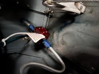
I have a carbureted O-360.
After landing with the fuel boost pump on and mixture rich I get a smell of fuel that goes away. This happens every time on landing:
I just “adopted” my recently purchased and RV-8A and did my transition training. It is a wonderful aircraft to fly. Lots of minor squawks but a possibly worriesome one that I wanted to consult the experts on this forum on.
I have a carbureted O-360.
After landing with the fuel boost pump on and mixture rich I get a smell of fuel that goes away. This happens every time on landing: