What's new
Van's Air Force

Don't miss anything! Register now for full access to the definitive RV support community.

Bendix dual mag and ACS A-510-2 questions

ccsmith51

Well Known Member
I have an O-360-A1F6D in my RV-4, and it has the Bendix dual magneto. I believe that one side has an impulse coupling, but I can't find out how to determine which side it is?

I assume that the left mag is on the left side of the mag housing, when viewed from the rear. If that is the case, which side has the impulse coupling?

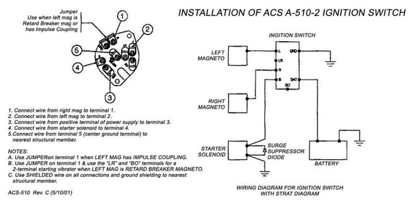
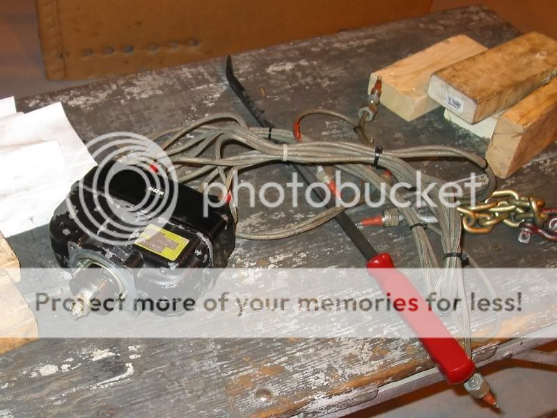
The question comes from me getting ready to replace my panel and wiring. I have an ACS A-510-2 ignition switch. The installation instructions I downloaded from Aircraft Spruce say to place a jumper between the two lugs at position 1 if the left mag has an impulse coupling. Position 1 in the photo below is the two terminals close together at the 1:00 position. As can be seen, a jumper is not there.

1osv3n.jpg


So, what does this mean? Can the impulse coupling be on the right mag, and then a jumper is not used? If the impulse coupling is on the left mag, and the jumper is not on the switch, what issues does that cause?

Finally, there is an ACS Ignition Switch Service Bulletin SB92-01 out, and a service kit available, but I cannot find when it was issued and whether my switch falls under the SB. Does anyone know how I can tell?

Thanks in advance for the help,

PS: during the rewiring all terminals will be replaced with proper types, attached using a ratchet crimper... :)
 
If that mag is the same as on my O-320-H2AD, the impulse coupling is on the end that mounts to the engine and works for both sides at the same time.
 
If that mag is the same as on my O-320-H2AD, the impulse coupling is on the end that mounts to the engine and works for both sides at the same time.

Thanks for the input, Curtis. According to Wikipedia the O-320-H2AD has the Bendix D4RN-2O21 dual magneto. According to the same source, the O-360-A1F6D has the Bendix D4LN-2021.

Interesting that the only difference in the numbers is an "R" for yours, and an "L" for mine. Can anyone shed any light on the differences between the two mags?

If in fact the impulse coupling is for both mags, then the question for the electrical experts is do I need the jumper on the ignition switch?
 
Left Side

For the O-360 (at least on mine), the Impulse Coupling is on the left side. You don't want the right mag to fire during start to prevent kick-back that will eventually tear up the starter.

You can tell the Bendix with the coupling because it looks like it has about a 1.5" spacer between the mag and the engine block--that's the coupling.

My guess is that the jumper is to make sure the right mag will remain grounded when you have the ignition in the START position. I have independent mag switches so I'm not sure about the internal wiring of a combined switch. But you definitely don't want the right side firing with the starter engaged.

-Matt
402BD
 
If both mags have an impulse coupler you do not need the jumper which is how your switch appears to be wired.
 
The "L" vs "R" MIGHT be the rotation direction of the drive end?? More research is needed and my magneto book is out at the airport.
 
The L&R refer to the magneto rotation. Since both mags are on a common shaft the impulse coupling retards both mag halves. This means you don't need the little jumper tab on the switch. Both mags will be retarded at start, so both can and should be firing.
 
shield ground to switch?

I noticed that in the picture the shields for the P-leads are going to the GND post on the switch.

The diagram that ACS has for the switch (shown below) does not show the ground from the P-leads going to the switch GND post. The shields (I think) are grounded to the engine and the engine to the frame and going to the OFF position on the switch grounds the P-leads.

I don't know if having the shields attached to the GRD on the switch does anything bad. My plane (which I bought already built) was wired that way but I changed it to agree with the ACS diagram. I did not notice any change in performance and shut down the engine the first flight of every month using the switch to make sure neither mag stays hot with the switch in OFF. It has always worked correctly.

A-510-2-INSTALL-DIA-no-M.jpg


As an aside, I have the same engine but mine has fuel injection added, and therefore have the same mags and have been wondering the same thing. Do I need the jumper? Right now my key switch does not have it and after 4 years and 350 hours of flying and many starts I have not had a kick back (thankfully).

My experience seems to confirm what Walt and aerhead posted.
 
Last edited:
Thanks for all the input. It appears that my switch is wired correctly for my particular engine.

Bubblehead, the shields are atached to the ground terminal on the switch, and that terminal is grounded to the airframe close by. The diagram you showed, which is the same diagram that I use, says to ground the shield to the nearest structural member. That is kinda how mine is wired, so I think it will be OK.

Thanks again, all, ain't VAF great!!
 
Mags

I have the same mag. and others are correct in that mag drive retards both the "L" & "R" mags.

I start mine on "both" hoping for better starts. You can start on "L" "R" or "both". I'm guessing that if you jumper from "L" to "R" you wont be able to do a mag drop test. Not studying the prints well, looks like Killing one will probably kill both sides.
 
One other thing. Anyone know about the switch SB? I thanks.

If memory serves me, the switch should have a red dot of paint on one of the screw heads at the back if the SB has already been incorporated at the factory.
From your picture it looks like the left screw has some paint on it?. If that is the case you are good to go :)

Edit: Here is a link with more information http://rgl.faa.gov/Regulatory_and_Guidance_Library%5CrgAD.nsf/0/B8ABD56539B4684886256A3E00759DBF?OpenDocument
 
Last edited:
If memory serves me, the switch should have a red dot of paint on one of the screw heads at the back if the SB has already been incorporated at the factory.
From your picture it looks like the left screw has some paint on it?. If that is the case you are good to go :)

Edit: Here is a link with more information http://rgl.faa.gov/Regulatory_and_Guidance_Library%5CrgAD.nsf/0/B8ABD56539B4684886256A3E00759DBF?OpenDocument

Thanks for the info and link. According to that document, based on the manufacture date of my switch, it should be OK unless there is no surge suppressor diode across the stater relay. If there isn't, then I need to get the service kit, which includes the diode. I'll check this weekend. Thanks again!
 
Engine trouble

Hi,
I am trying to start my O320 engine. When I turn the key on starter position engine seems to run normally, but as soon as key returns to both engine shuts down....I am not sure Key wiring is effective...
 
If you have a timing box, you could check the timing on both mags. Mag without impulse coupling will fire close to 25 deg BTDC. Mag with impulse coupling will fire later with the "click". I'm sure if you had one mag without impulse coupling firing early because of no jumper, you would know it by now.
 
I think there is a misunderstanding with the title of the OP of this thread. A dual magneto is an arrangement in which the left aircraft magneto and right aircraft magneto are contained in a single housing and operated by a single magnet rotor and engine drive.

With a single drive that has a impulse coupling both side are affected exactly the same.

141_4163.jpg
 
Back
Top