
Van's Air Force
You are using an out of date browser. It may not display this or other websites correctly.
You should upgrade or use an alternative browser.
You should upgrade or use an alternative browser.
Tail wheel cold weld
- Thread starter gmpaul
- Start date

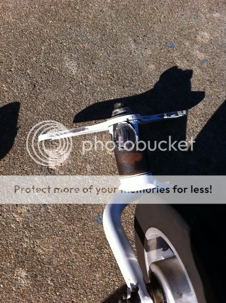
First time I've seen that hapen! I've seen the bolts that hold the knuckle to the spring shear, but never that weld.
Bob Kuykendall
Well Known Member
...I was pushing plane back into hanger and bumped a inch and a quarter door lip to roll into the hanger...
If you were going backwards when you hit the 1.25" high lip, I think that it is possible that the loads on the weld were actually pretty high. As you go backwards, a load applied to the tailwheel by an obstruction will tend to pivot the tailwheel spring down, increasing the vertical force on the tailwheel and making it harder for it to roll over the obstruction.
snoop9erdog
Well Known Member
Oops
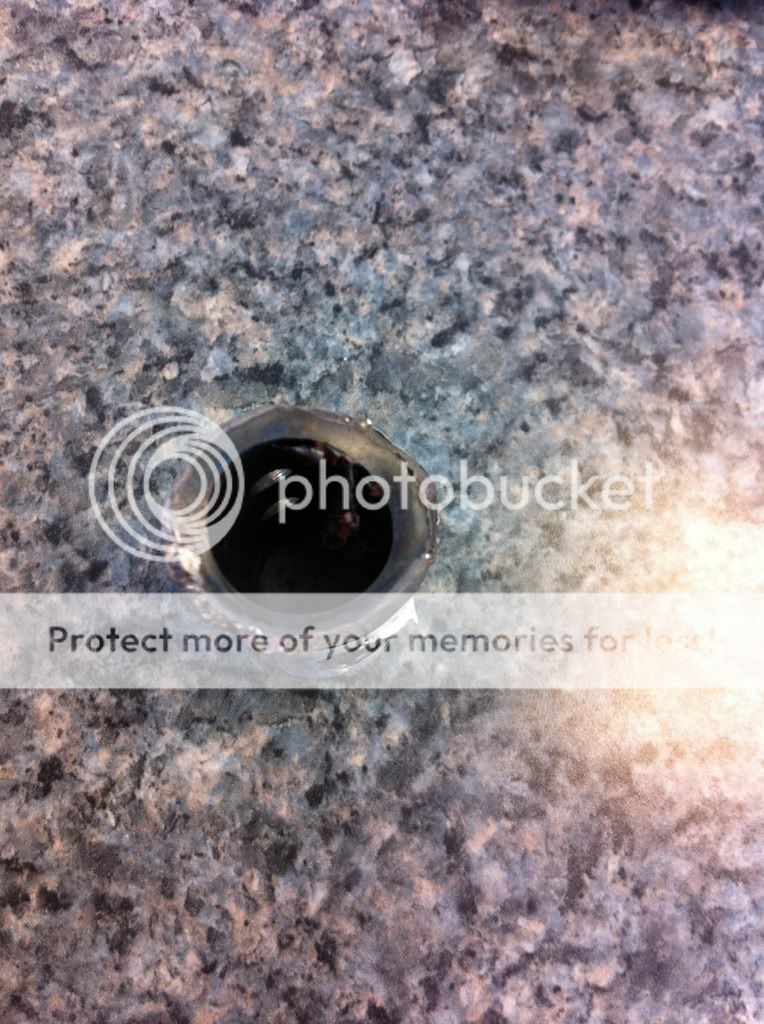
Based on the photos/visual inspection it looks as if it was a lack of weld penetration. I'm assuming that the material is 4130 chromoly? Correct me if wrong, but it looks like a Bell.
With proper penetration, a tailwheel joint should withstand a tension load with no problem. I've tested firsthand a chromoly T joint in tension that didn't fail until @ 7200 psi. The tear occured in the heat affected weldzone and not in the weld joint itself.
It would be interested to know the weld process (TIG or MIG) and the filler rod used for these weldments.
randyintejas
Well Known Member
"What brand is that tailwheel."
Looks like the Vans tail spring on an aftermarket tail wheel. the same thing I have.
Looks like the Vans tail spring on an aftermarket tail wheel. the same thing I have.
David Paule
Well Known Member
I've tested firsthand a chromoly T joint in tension that didn't fail until @ 7200 psi.
A properly designed and fabricated weld in steel such as 4130 should have a strength much higher than that. Did you drop a zero -- that is, should it have been 72,000 psi?
According to MIL-HDBK-5H, page 8-137, in table 8.2.2.1.1(b), for 4130 that's been normalized after the weld (common practice with gas welding), the strength adjacent to the weld should be at least 80,000 psi.
If nothing is done to the region after welding, the tension strength should still be at least 51,000 psi, according to the same page.
Dave
brad walton
Well Known Member
Manufacturer
It does look like a Bell tail wheel fork. But the swivel is probably Van's. Bell builds the forks but suggests you install it on the Van's swivel, which it fits perfectly so there is no need to redrill the assembly to the tail spring.
It does look like a Bell tail wheel fork. But the swivel is probably Van's. Bell builds the forks but suggests you install it on the Van's swivel, which it fits perfectly so there is no need to redrill the assembly to the tail spring.
snoop9erdog
Well Known Member
Yes
Dave, your correct....70ksi failure.
It also appears to be the tailspring from van's as a few have mentioned. This weldment may have been the unlucky lemon out of thousands of tailsprings? Let's hope that that is the case.
Dave, your correct....70ksi failure.
It also appears to be the tailspring from van's as a few have mentioned. This weldment may have been the unlucky lemon out of thousands of tailsprings? Let's hope that that is the case.
WingsOnWheels
Well Known Member
Wow, that is a very poor weld job. As an old pipline welder that was teaching me stick welding as a kid would say, "That one won't pass X-ray".
longranger
Well Known Member
It does look like a Bell tail wheel fork. But the swivel is probably Van's. Bell builds the forks but suggests you install it on the Van's swivel, which it fits perfectly so there is no need to redrill the assembly to the tail spring.
Maybe the title of the thread can be changed - the tailwheel fork didn't fail, Vans spring to swivel weld did. I'd hate to see Bell tailwheel forks get a bad rap on a misunderstanding.
cka357
Active Member
Cold Weld
I can't help but to study the photos in hopes of providing some useful information to the group. Please forward these photos to the mother ship. I'm sure they would want to do some failure analysis on these components or at least be aware of the joint failure to determine preventive measures of inspecton and avoiding future occurrences.
Chuck
To answer a few questions
The brand of tail wheel is what comes with the kit. I did install a Bell tail wheel but that is just an insert that fits in the original WD-101.
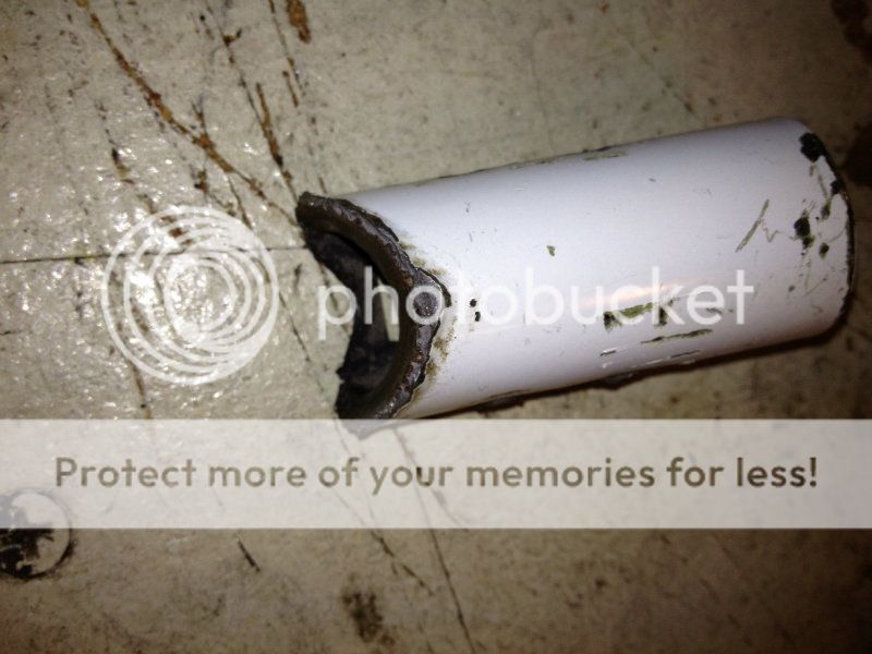
The penetration of the weld looks very shallow and that was from 5:00 to 8:00 and 12:00 to 1:00 the rest was not holding (to my untrained eye). So moving backwards would put the most stress on the 12:00 to 1:00 weld.
On the bright side I wasn't landing! No better place than in your own hanger for it to break. I called Vans and talked to Joe in support. He said I was describing a quality control problem and send him these pictures.
Yes I think I did get the one lemon out of a thousand tail spring kits.
Thanks every one for the support
G P
The brand of tail wheel is what comes with the kit. I did install a Bell tail wheel but that is just an insert that fits in the original WD-101.
The penetration of the weld looks very shallow and that was from 5:00 to 8:00 and 12:00 to 1:00 the rest was not holding (to my untrained eye). So moving backwards would put the most stress on the 12:00 to 1:00 weld.
On the bright side I wasn't landing! No better place than in your own hanger for it to break. I called Vans and talked to Joe in support. He said I was describing a quality control problem and send him these pictures.
Yes I think I did get the one lemon out of a thousand tail spring kits.
Thanks every one for the support
G P
David Paule
Well Known Member
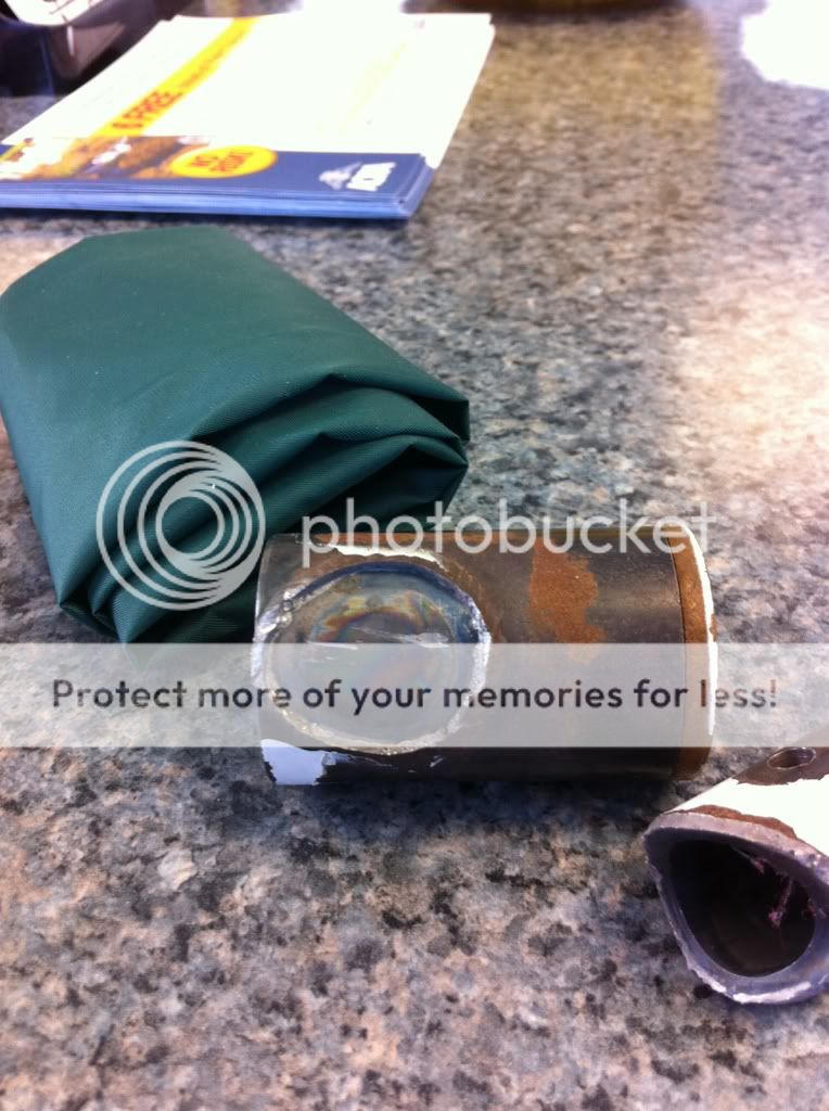
Let's also note the presence of corrosion, which could have been a contributing factor.
Dave
Dave
This looks like a bad weld, poor penetration, also maybe not normalized after or allowed to cool to fast. Another possibility is the wrong filler rod was used. You may want to ask the manufacturer if the welder was aircraft certified for steel.
Then again you may want to buy a replacement from someone else.
Or, even more fun, take a semester or two and learn to TIG weld at your local community college and take you aircraft certification exam. I think that is one reason why most of us have experimentals is to learn new skills.
Then again you may want to buy a replacement from someone else.
Or, even more fun, take a semester or two and learn to TIG weld at your local community college and take you aircraft certification exam. I think that is one reason why most of us have experimentals is to learn new skills.
Russ McCutcheon
Well Known Member
Not looking too good, broke right through the center of the weld as in weld failed, don?t see too much of this, never seen it on any RV part regardless the welder.
To be clear we don?t build the parts pictured in this thread.
To be clear we don?t build the parts pictured in this thread.
AZtailwind
Well Known Member
Agreed.Poor weld and they likely used the wrong filler rod. Easy to fix.
All the rust doesn't help. Maybe some triangle finger stringers would provide 150% loads to hold up on excess stress.
Russ McCutcheon
Well Known Member
I agree, that's what I would do too.I'm with Bob and Brad.
Clean up the parts, prep the parts and (properly) reweld.
Then you won't have to drill new bolt holes in alignment with the existing holes in the spring.
Filler rod choice isn't a big deal unless the designer intends the part to be heat treated. I'd expect ordinary ER70S-2 (or -6) or ER 80S-D2 here. Post weld temperature control is probably not an issue for practical reasons.
The base problem appears to be simple lack of penetration. A pretty little perfect stack-o-chips is wonderful on thinwall tube, but this part has wall sections of what, 0.1875"? All that wall thickness is useless if you can't see the weld from the inside of the tubes. You want a WELD, not a weld.
Let's not neglect to inspect parts prior to installing them, regardless of source.
Weld
Can we PLEASE let go of the erroneous statements "not normalized after" and such.
Russ McCutcheon stated within the last few days that none of the RV parts that they make are post weld treated in any way. (NO normalizing)
This type of tailwheel "hub" is used in many other aircraft besides the RV's. There is little if any history of failures.
When TIG welding material of this thickness a slightly different welding technique is necessary. The torch should be moved at a slower rate than when welding thin wall material. This will provide a proper thickness of weld buildup. In this case the weld buildup was much too shallow.
Another possibility is that the finish point in the weld was done abruptly, resulting in too rapid cooling and a crater in the weld with a likely pinhole.
If the amperage is slowly reduced while moving the torch in a small circle this will not happen.
The crater and or pinhole is a perfect starting point for a crack which will then progress along an otherwise good weld. The rust contributes to this.
randyintejas
Well Known Member
Chad,
As Dan said: All that wall thickness is useless if you can't see the weld from the inside of the tubes
Look for full penetration of the weld, holes,cracks in the weld and rust.
As Dan said: All that wall thickness is useless if you can't see the weld from the inside of the tubes
Look for full penetration of the weld, holes,cracks in the weld and rust.
Last edited:
David Paule
Well Known Member
Is there reason to or any possible way to non distructively test tailwheel knuckles out there today? Can a bad weld be noticed visually?
You can have an inspection facility check for cracks, but that doesn't assess penetration of the weld.
Also, worth mentioning is that a good weld design will specify not the penetration but the dimensions of the applied weld. After that, quality control (could be the welder, of course, taking a look at it) will verify that the design has been met during the welding.
Dave
ExtraKatana
Well Known Member
another tail-wheel incident while backing over the hangar door lip!
Looks like a job for Anti-Splat.
sorry....sorry
Looks like a job for Anti-Splat.
sorry....sorry
vfrazier
Well Known Member
Yikes! I'm glad that it wasn't one of our tailwheel mounting sockets! Ours use a different bushing.
Normally, it's the bolts that break, often due to poorly (loose) drilled holes. That should be of much more concern to the average builder.
I wouldn't let this 1 in a 1000 occurrence cause any lost sleep. Nonetheless, this is a good reminder to keep a close eye on ALL parts of your plane, even the greasy, dirty bits way in the back.
Jason Krause
Active Member
possible replacement
I agree, it's very rare occurrence and that weld should handle the load without worry.
Here is a possible future replacement.
http://www.vansairforce.com/community/showthread.php?t=95453
I agree, it's very rare occurrence and that weld should handle the load without worry.
Here is a possible future replacement.
http://www.vansairforce.com/community/showthread.php?t=95453
vfrazier
Well Known Member
And here is another possible replacement: http://www.flyboyaccessories.com/store/index.php?main_page=product_info&cPath=66&products_id=413
We use a high tech plastic bushing. Simple and superior to the standard bronze bushings. We have been supplying these for over 5 years now. Long wearing, easily replaceable, and no known problems as long as you don't powder coat the part and heat damage the bushing!

We use a high tech plastic bushing. Simple and superior to the standard bronze bushings. We have been supplying these for over 5 years now. Long wearing, easily replaceable, and no known problems as long as you don't powder coat the part and heat damage the bushing!
Last edited:
David Paule
Well Known Member
Here is a possible future replacement.
In the photos the area that failed in this instance look identical to the construction of the part that you're referencing.
Dave
JonJay
Well Known Member
In the photos the area that failed in this instance look identical to the construction of the part that you're referencing.
Dave
They have the same joint as the Van's one that failed. Really, really rare to see this. I have never seen or heard of one failing here.
The tailpost upgrades are offering a promise of less maintenance, so they are just trying to make people aware there are other options. This person may be in the market for a new tailwheel post if he does not repair this one. Marketing opportunity.
vfrazier
Well Known Member
Many of us do a dye penetrant check on the lower engine mount/gear leg area. Perhaps checking the tailwheel mounting socket would be a good area to inspect once in a while?
Here's one from Grainger that should work:
dye penetrant test kit
You might also take a look at your tailwheel mounting socket welds. As Dan Horton pointed out, these are thick walled steel parts. The weld beads should be substantial. Here's a good example:
If your welds look puny, it is a very easy thing to fix by re-welding, or even adding a triangular gusset for "belt and suspenders" protection. I don't think the gusset is necessary if the weld is beefy though.
If you decide to re-weld, try not to overheat your bronze bushing. Stuff a hot dog into the hole to soak up the heat. When you're done welding, the hot dog will be cooked. Lunch is ready. Enjoy.
Last edited:
JonJay
Well Known Member
Many of us do a dye penetrant check on the lower engine mount/gear leg area. Perhaps checking the tailwheel mounting socket would be a good area to inspect once in a while?
Here's one from Grainger that should work:
dye penetrant test kit
You might also take a look at your tailwheel mounting socket welds. As Dan Horton pointed out, these are thick walled steel parts. The weld beads should be substantial. Here's a good example:
If your welds look puny, it is a very easy thing to fix by re-welding, or even adding a triangular gusset for "belt and suspenders" protection. I don't think the gusset is necessary if the weld is beefy though.
If you decide to re-weld, try not to overheat your bronze bushing. Stuff a hot dog into the hole to soak up the heat. When you're done welding, the hot dog will be cooked. Lunch is ready. Enjoy.
I the only time I have done a die penetrant it has been on bare metal. Would it not require you to strip any coatings off before using this kit?
rocketbob
Well Known Member
Rewelding will shrink the ID by a considerable amount. Usually when welding stuff like this if it can't fit back in the jaws of my lathe I set my mill up with a boring head/bar and shave a few thousandths off the ID to true the hole again.
The bushing should be pressed out to reweld. If its an oillite bushing have fun welding if its still in there, they tend to catch on fire readily.
The bushing should be pressed out to reweld. If its an oillite bushing have fun welding if its still in there, they tend to catch on fire readily.

snoop9erdog
Well Known Member
I the only time I have done a die penetrant it has been on bare metal. Would it not require you to strip any coatings off before using this kit?
Correct Jay, for best results the weld area neds to be cleaned and clear of paint, coatings, etc. Keep in mind that you are only going to discover surface irregularities/cracks and not penetration information...but the crack information is obviously useful for eventual failure.
JonJay
Well Known Member
Well, I hope to see the crack through the paint before it fails, if it ever does, as I am not going to strip off the paint and repaint my tail post to do a die penetrant check.Correct Jay, for best results the weld area neds to be cleaned and clear of paint, coatings, etc. Keep in mind that you are only going to discover surface irregularities/cracks and not penetration information...but the crack information is obviously useful for eventual failure.
If it ever does fail, I guess I will have a skid to land on. I bet a skid would keep the tail behind me quite well!
DavidBurton
Active Member
It would be interesting to see some well focused, close up photos of the failed weld areas. The fractured surface tells us how the weld failed. It could be in tension with a good ductile failure. This might indicated that the weld was done using a correct process but with a failure to achieve good penetration or large enough fillet. If the weld penetration is poor, a "failure to get the root out" there is a notch at the base of the weld that will be a crack initiator. You can read a discussion of a failure analysis caused by this here:
http://www.met-tech.com/crane-weldment-failure.html
If we see a brittle failure this could indicate poor filler material selection or poorly designed welding process.
Fatigue failure points to poor technique, poor materials selection and incorrect process.
When developing a welding procedure on a critical weldment it's common to analyze test components by doing cross sections and at least visual analysis of the welded parts. Unfortunately too many welders assume that globbing some filler material between the two parts they want to join will be sufficient. This became such a huge problem with mechanics welding trailer hitches on to car and truck frames without having any idea of what they were doing that the DOT banned this practice unless done by a certified welder. It's likely that the certified welder's insurance company prohibits the welder from doing it anyway.
If the welding process builds up too little heat or adequate filler material the thick tubing will quench the weld causing it to become brittle. Often an inexperienced welder will choose a welding rod that is much stronger than the base materials in an attempt to make a "stronger" weld. The much stronger filler material will not be ductile as compared to the base material and this can initiate a cracking caused by stress concentrations in microscopic areas adjacent to the weld leading to fatigue failures.
Just being a proficient welder doesn't insure that the finished weld will be satisfactory. A well designed welding process based on the materials and anticipated loads expected is necessary. If the loads are cyclic in nature like those experienced by this weld it is extremely important that the process developed insures that fatigue failures are prevented.
David
Metallurgist, destructive and non-destructive material testing engineer, forensic failure analyst and American Welding Society QC1 certified welding inspector.
Mike S
Senior Curmudgeon
David.
Metallurgist, destructive and non-destructive material testing engineer, forensic failure analyst and American Welding Society QC1 certified welding inspector.
The breadth and depth of knowledge available here never ceases to amaze me.
Originally I posted this to see if anyone else has had a WD-101 break.
So far it seems there is just one other (#35).
I am in communication with Vans and they want to make everything right (which I knew they would) since they are such a great company.
They requested the broken part and it should be in their hands next week.
I will post after I hear back from Vans.
G.P.
Bob Kuykendall
Well Known Member
It would be interesting to see some well focused, close up photos of the failed weld areas...
I definitely agree. But I would also like to see a free-body diagram that analyzes the stresses within the weld that prevail as the tailwheel passes backwards over a 1.25" obstuction. My suspicion is that this loading case gets close to the yield stress even for a properly-done weld.
JonJay
Well Known Member
I definitely agree. But I would also like to see a free-body diagram that analyzes the stresses within the weld that prevail as the tailwheel passes backwards over a 1.25" obstuction. My suspicion is that this loading case gets close to the yield stress even for a properly-done weld.
A properly done weld should not yield. The material around it might but the weld should not. If it does, there is something grossly wrong with the design of the part. With thousands of these tail wheel posts backing over hangar door tracks for many years, I think we would have seen more than one or two failures.
I inspected mine last night. The weld beading was significantly different than the photo's shown of the broken parts. Much wider bead and penetration evidence (material caving) along the sides of the weld.
vfrazier
Well Known Member
Rewelding will shrink the ID by a considerable amount. Usually when welding stuff like this if it can't fit back in the jaws of my lathe I set my mill up with a boring head/bar and shave a few thousandths off the ID to true the hole again.
The bushing should be pressed out to reweld. If its an oillite bushing have fun welding if its still in there, they tend to catch on fire readily.
We weld these all the time after machining the I.D.s and have no issues with welding shrinkage on these thick walled parts. After welding, we also 100% inspect them just to make sure.
Properly done, the tailspring and the socket will make a "gas-tight" seal. You can feel the air compress when you insert the tailspring, and you get a nice "pop" when you pull it out.
Don't weld with the bushing in place. As Bob pointed out, they don't take kindly to the heat.
Skykingbob
Well Known Member
Thanks David!!
David.....that was very interesting.....GREAT INFO......thanks for taking the time to post and link....I love this stuff!!!
Just being a proficient welder doesn't insure that the finished weld will be satisfactory. A well designed welding process based on the materials and anticipated loads expected is necessary. If the loads are cyclic in nature like those experienced by this weld it is extremely important that the process developed insures that fatigue failures are prevented.
David
Metallurgist, destructive and non-destructive material testing engineer, forensic failure analyst and American Welding Society QC1 certified welding inspector.
David.....that was very interesting.....GREAT INFO......thanks for taking the time to post and link....I love this stuff!!!

