I've really enjoyed following this, and learning along the way.
I am really happy that the initial issue lead to an increased capability in the EFII system that solved the problem. I thought it interesting that Ross was open-minded enough to make the change after earlier saying that it was a mask for the root problem. He was likely correct, but was open to the 'symptomatic relief' anyway to address a common systematic problem.
Yes, it would be great if we all had manifolds that flowed well and evenly.
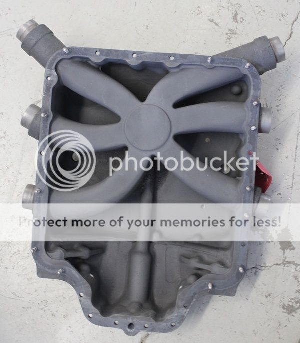
I feel pretty lucky to have the angle-valve horizontal induction manifold which does seem to flow very evenly, right out of the box. My GAMMI spread is less than 0.2 gph, right out of the box. No doubt the plenum volume, and runner design is a big part of that.
Interesting that the fuel divider plays much of a role at cruise fuel flows. It has a pretty symmetrical geometry.
Excuse the thread drift here for a funny story:
I got a huge chuckle out of DanH bringing up the Bosch D-jetronic. I spent a lot of time fussing and toying with the D-jetronic on my 1971 Volvo 1800E race car. I really hated it. Its fundamental problem was relying on manifold pressure, rather than a direct measurement of airflow. A real challenge for the old analog computer box was that airflow is a non-linear function of manifold pressure. The manifold pressure sensor was pretty low quality by todays standards. A small error in manifold pressure near WOT would give a very incorrect mixture. But the bigger issue for me was that it is completely un-adaptable to changes in engine breathing. Improved breathing means more airflow at the same MAP, and so it got leaner as I improved the engine. Eventually, it had a horrible lean spot at the RPM where the induction tuning gave the best flow, to the point where it would miss. I tried adding a trim pot in the computer box to bias the mixture, and I tried fudging the calibration of the MAP sensor. Marginally solved the issue, but never perfect. And then, trying to get it to pass California smog tests. I will spare you all the onslaught of swear words I've directed at the D-Jetronic over the years.
My final solution was to find a Bosch K-Jetronic system off of a 1975 Volvo. What a wonderful system that was. It used a direct mass-flow sensor, and a constant-flow injection. (sound familiar?) That made the system much more amenable to engine changes. My engine finally ran right, delivering about 170 hp on 94 (R+M)/2 gas from an old B-20 overhead-valve motor. Not much by todays standards, of course.
That system was so versatile that it was the backbone of the first (or one of the first) production FI systems with a closed-loop mixture trim from an O2 sensor. It was called Lambda-sond. I think it was the first, but could be wrong.
Anyway, just thought I'd share that -- The old CIS, whether it be Bosch or Bendix, is not a bad way to go.