What's new
Van's Air Force

Don't miss anything! Register now for full access to the definitive RV support community.

RV-9A, pilotjohns

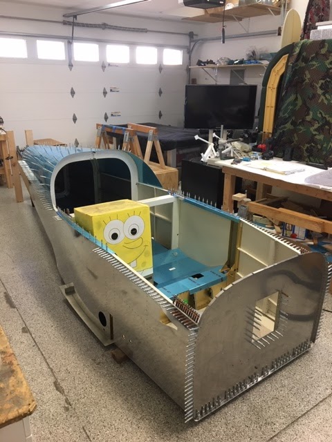
Small Steps are Still Progress

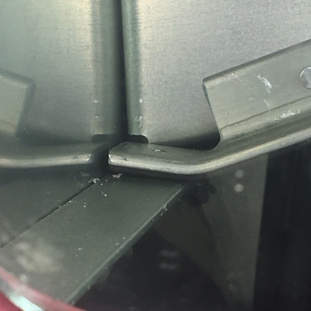
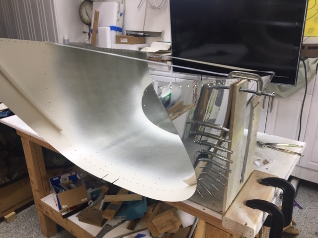
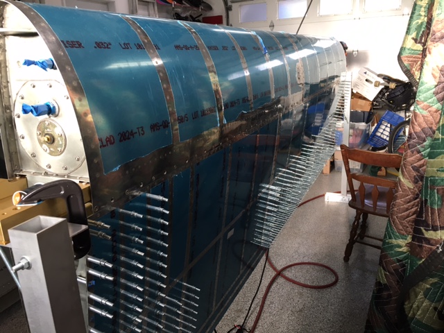
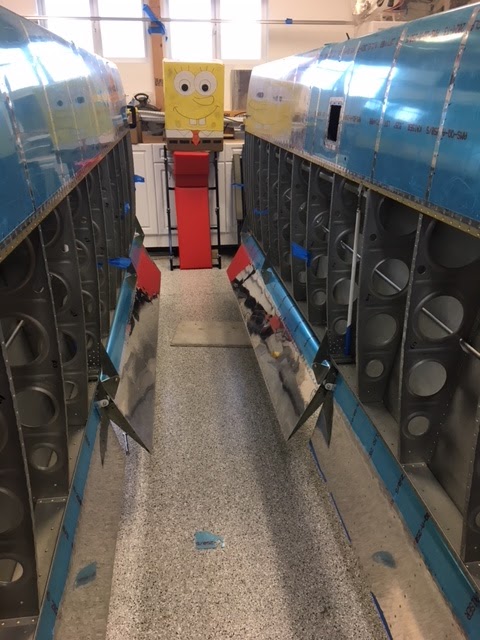
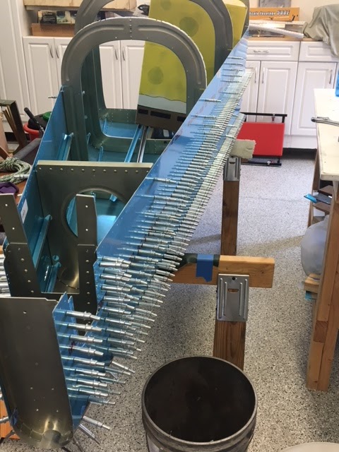
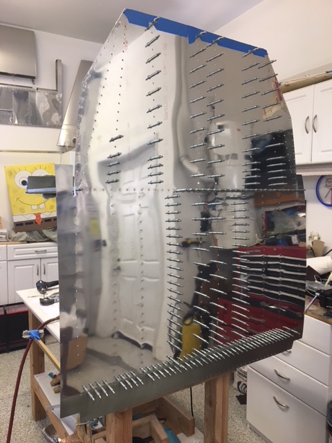
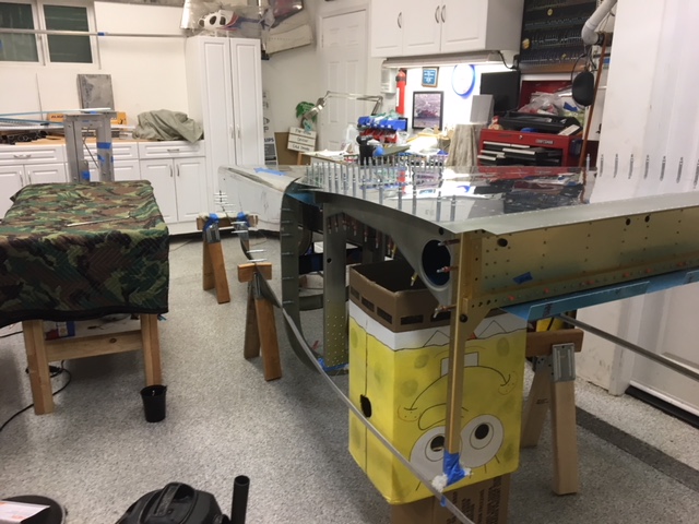
As the wing build continues, no real drama. The leading edges went on without much trouble; not nearly with the difficulty I envisioned from reading other blogs. As it turned out, most of the leading edge to spar rivets were reachable with the squeezer. I only had to drive about 10% of them, and of those only 5 on the right wing were blind and needed two people. I used a short double offset and taped it to the gun so it wouldn't rotate.


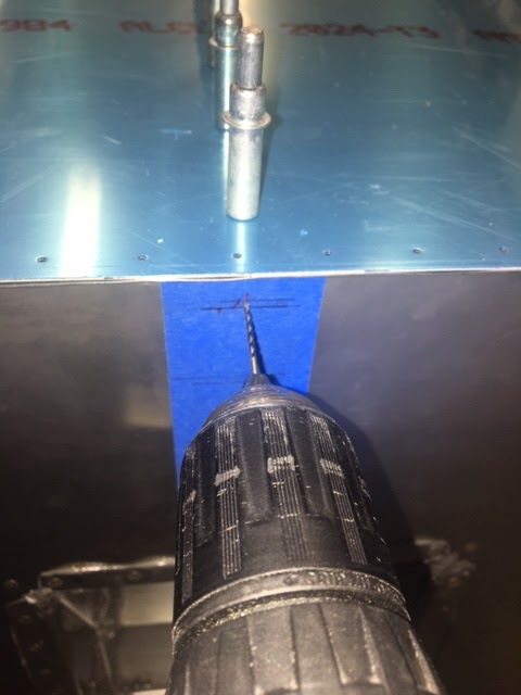
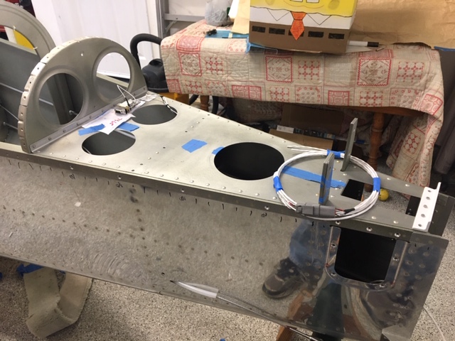
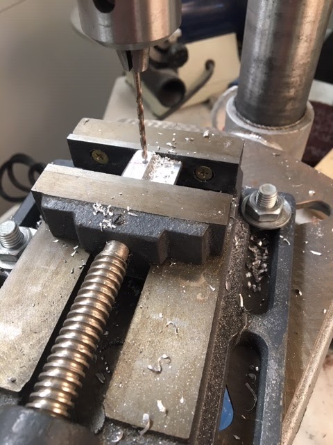
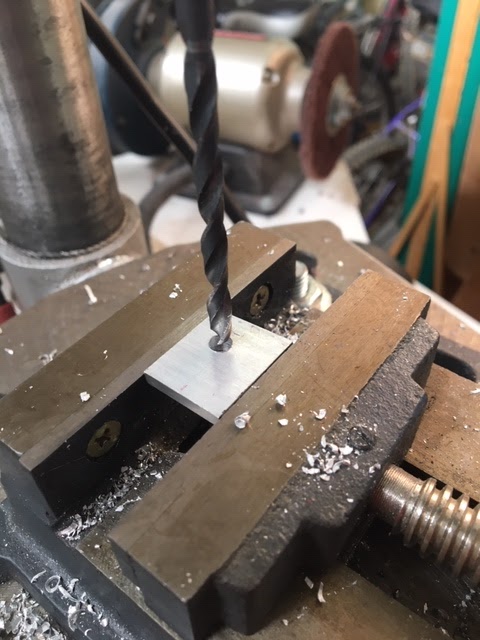
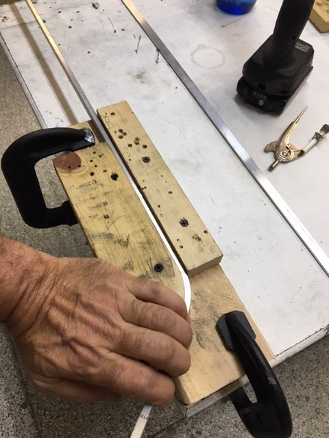
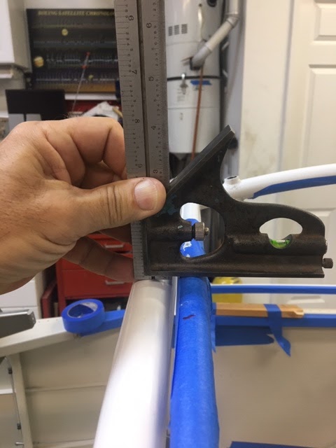
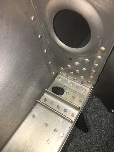
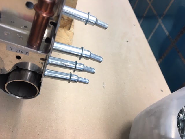
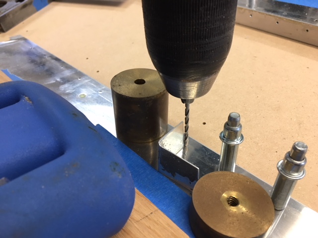
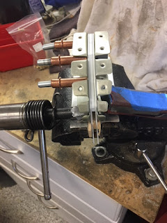
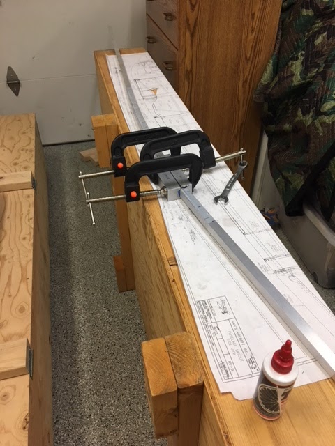
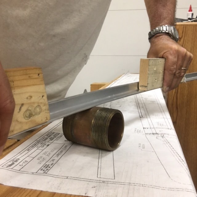
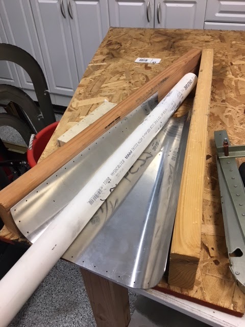
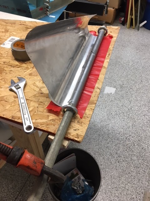
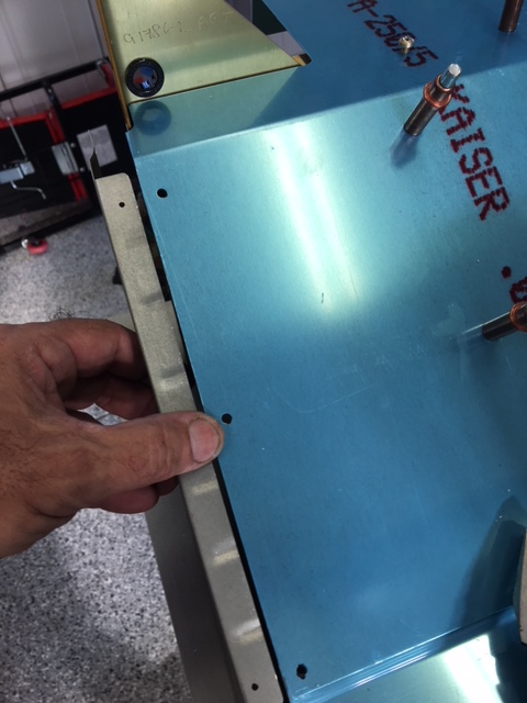
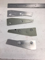
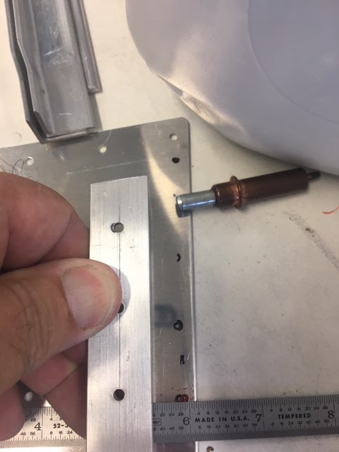
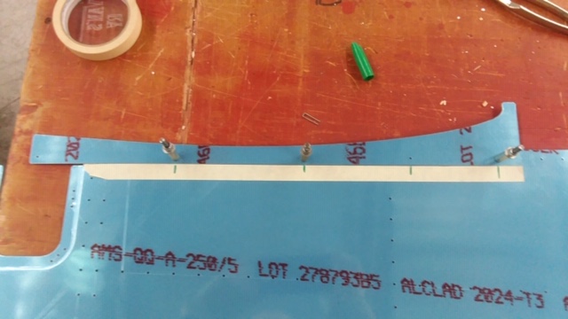
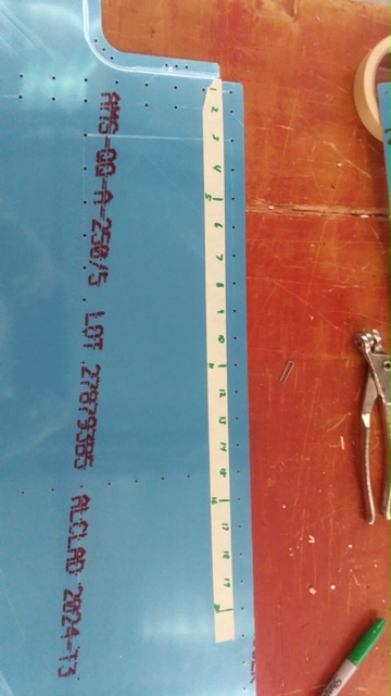
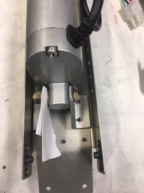
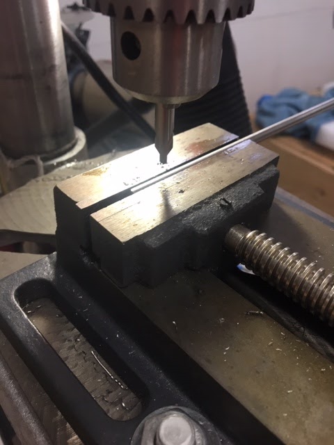
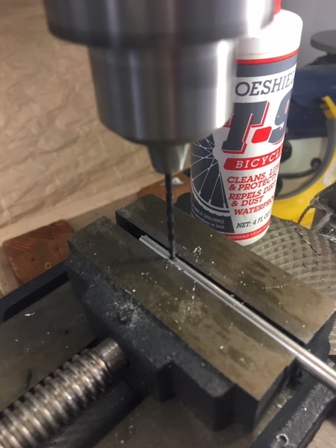
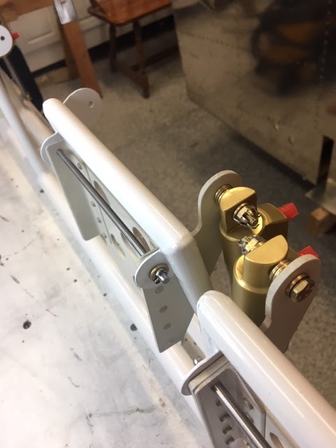
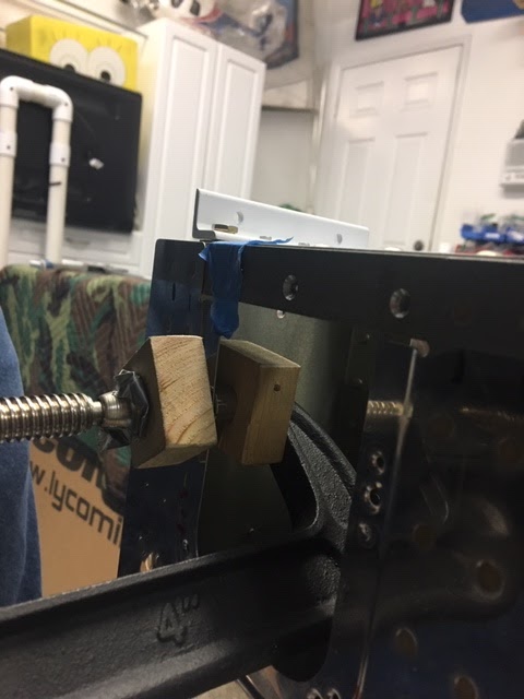
For the splice strip between the tank and the outer leading edge skin, I tweaked the nut plates to better conform to the skin using a vise and some scrap brackets. This worked out well.

IMG_1343.JPG


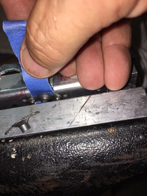
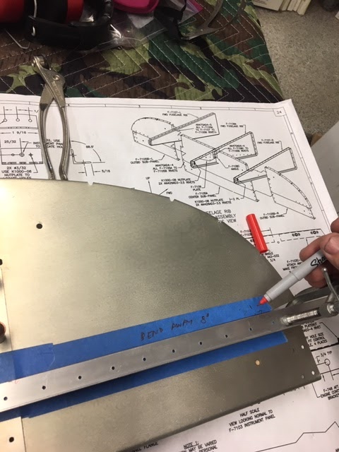
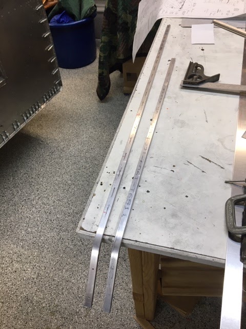
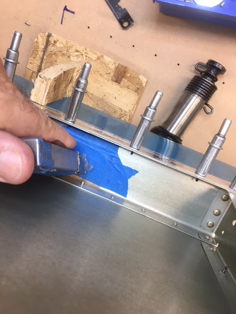
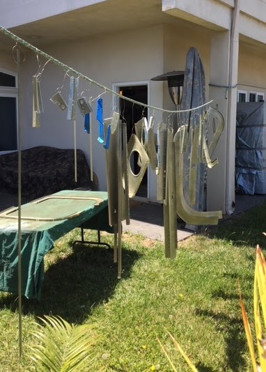
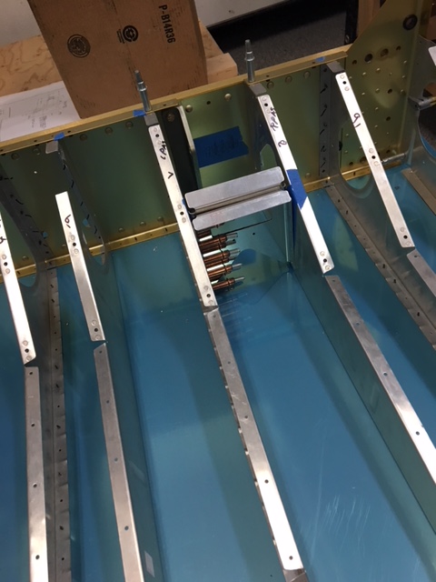
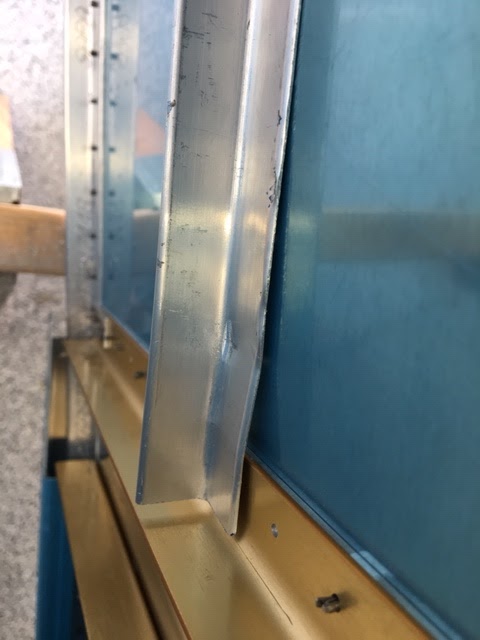
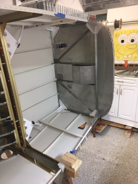
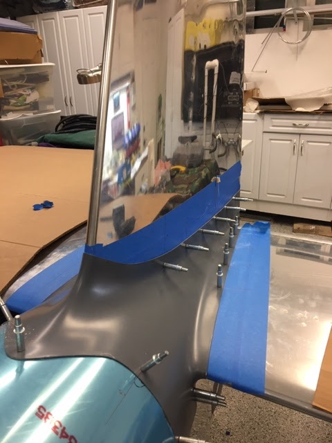
After installing the tanks, I noticed the skin thicknesses aren't all the same. Some are 25 mils , others are 32 mils. I wish I would have beveled the skins before assembly to make this transition smoother, but maybe there will be a chance to smooth the 7 mil step before paint.


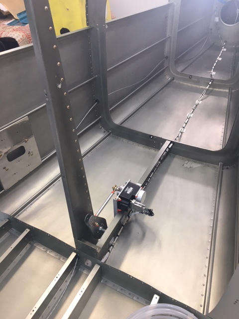
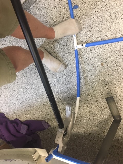
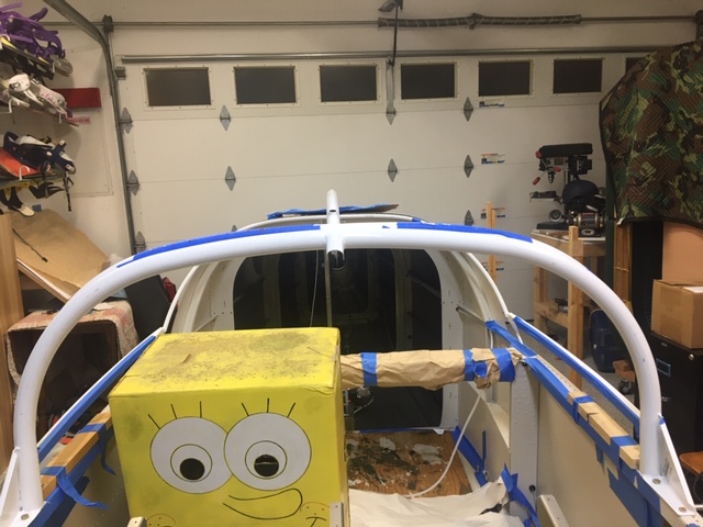
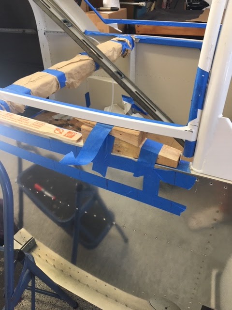
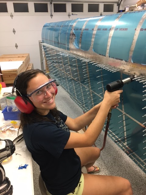
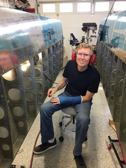
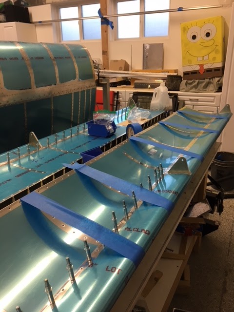
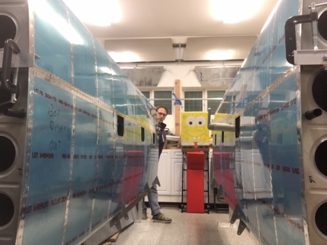
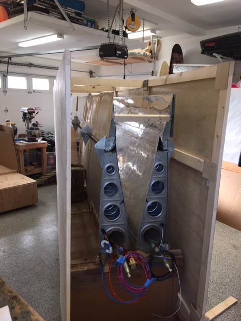
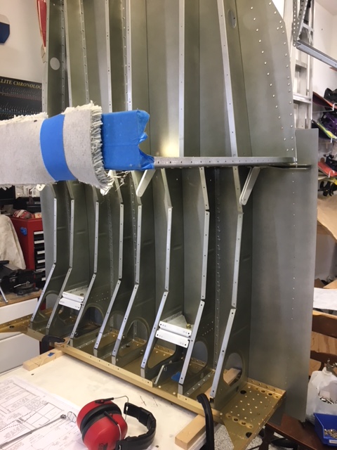
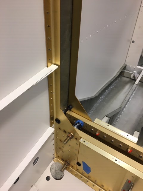
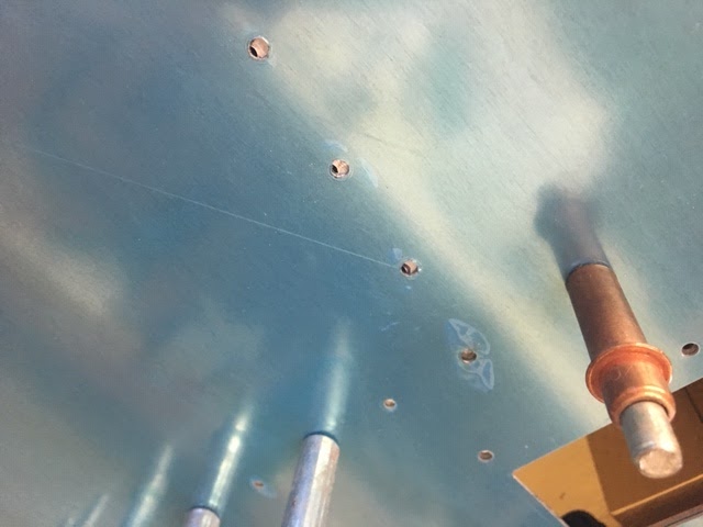
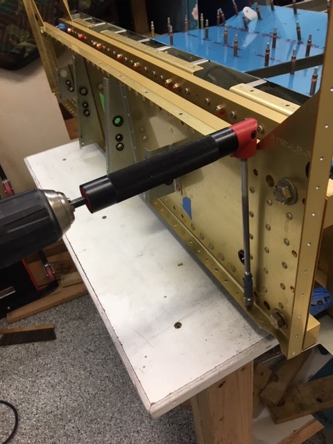
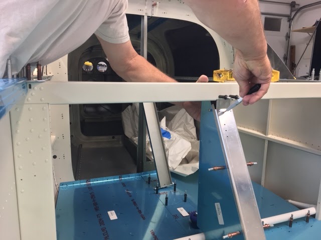
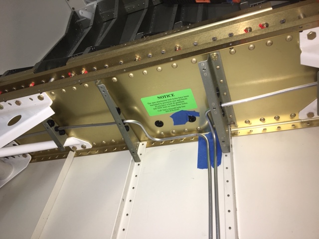
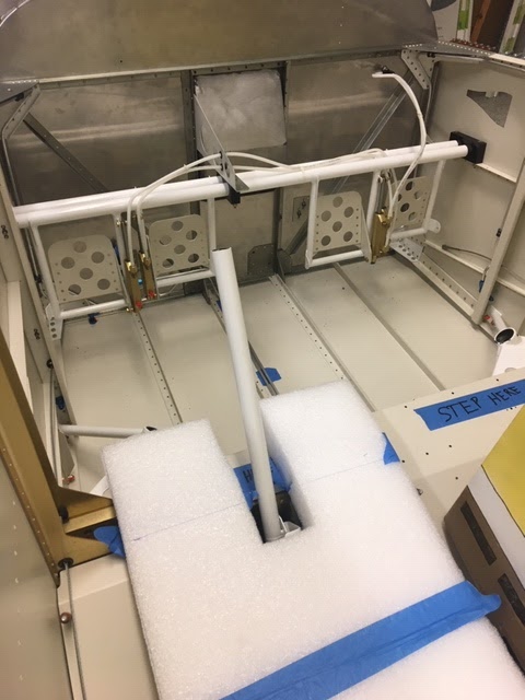
I started riveting the skins on with my resident engineer-in-training. I am still trying to work out the best technique. I tried the long offset back rivet tool, but this takes so much umph on the gun the rivet heads aren't pretty; acceptable, but not pretty. So we tried the normal method as in the picture. This worked out well for the ribs, but still looking for a better method for the skin to spar rivets.
IMG_1382.JPG
 
Last edited:
Top Wing Skins

Look no clecos! A few of the rear spar rivets are still not in near the root; it seems these will be easier to squeeze once the wings are out of the build stands.

The easiest way I found to do this was from the trailing edge. Starting with the center rib of each skin, I would rivet the skin to the rear spar between the two center ribs. Then work up from the trailing edge on each rib. I could just reach the fourth rivet above the J stringer by laying on a creeper.

IMG_1412.JPG
[/IMG]

After each skin was done on the lower portion, I would then corral a helper and rivet each rib the rest of the way up and then the main spar. I found a helper with a tungsten bucking bar was the easiest. I also used a wi fi endoscope camera hooked to my iPad so I could see around the other side and validate each rivet as we went. For $40 on amazon, the endoscope camera was well worth it. After a while, my friend would understand a good rivet and we would move along.

IMG_1408.JPG


I took advantage of my rivet buddy not wanting to go home (because of traffic, not the wife, so he said) and was able to get all the top rivets on the right wing too. The rest I can get from the bottom with a creeper.

IMG_1413.JPG


The wing is going slower than I anticipated, but I am taking my time and keeping the quality up.
After checking the twist, everything is as before. I did notice the right skin had to be cleco'd in a certain order to get all the holes to line up, so I ended up clecoing the skins on twice and using a cleco in every hole. There must have been some sag the first time. I am glad I didn't start riveting until both skins were on and fully cleco'd in place.

(Wow the shop is a mess!)
 
Last edited:
Flap and Aileron Brackets

Making steady progress on the wings. Everything pretty much to plan. One note: the instructions were written long before the extra aileron brace was engineered. So the instructions say to install the aileron brackets before the flap brackets. This build order needs to flip around now. The flap brackets need to be installed prior to the aileron brackets since the extra reinforcing interferes with the rivets as seen in the picture below.

IMG_0285.JPG


One thing to note, the bottom skin rivets can still be accessed with this brace in place; on the RV7, I believe the brace interferes with the skin rivets, not a problem on this RV9.

Moving on now with the flaps and ailerons...
 
Last edited:
The End (of the Wing) is Near

The end is near, both of 2017 and this wing build.

The ailerons are finished, and I am quite happy with the results. One aileron trailing edge is dead straight, the second took a little work to get out a very minor ripple; I think the ripple was caused by not riveting the trailing edge together as soon as the pro-seal was dry and letting the trailing edge sit unclamped for a few days. No worries should be fine.

I think the secret to building ailerons with no twist is the leading edge straightness. I spent a little extra time making sure the bottom skin was absolutely flat from the stainless steel leading edge weight to the spar. Since drilling the leading edge is very difficult due to the super hard stainless steel, I ended up having some extra "lightening" holes in the stainless steel bar. During final assembly, I made sure the leading edge ribs sat flat on my super flat surface plate (granite kitchen counter top). Once the leading edge is riveted to the spar, the aileron becomes enormously stiff. I am glad I took the extra time to make this part perfect.

IMG_0287.JPG


For the trailing edge drilling, I make a simple metal guide; should have done this long ago.

IMG_0320.JPG


I am currently working on the flaps and planning out the internal stuff that needs to go in before the bottom skins are on. I am thinking I will fully install the heated AoA pitot tube, and the autopilot servo for the future G3x panel. I am planning the magnetometer for the Left wing tip and the VOR antenna for the right. So my present plan is to not pull any wires for those until the tips go on in a year or two. The wings already have conduit for the wiring, so pulling the wires should be easy. [I](updated 2/2018, AP in right wing, so magnetometer in left)[/I]
As for the lights, I saw some new Baja Design that seem choice, but with the pace of technology, still not sure if I will install now.
 
Last edited:
Looking good! I put Xponder and APRS antennas in one wing tip and NAV/Marker Beacon in the other. The magnetometers went on the Horizontal Stab platform just in front of the Vert Stab. Have had no issues with the arrangement. Merry Christmas..... and yes, get the QB Fuselage!!
 
Flaps

Moving on to the flaps.
It is after New Years and I still have a little bit left on the wings, namely the flaps and the internal mechanisms.

The normal match drilling and bracket fabrication went as per the instructions, no drama there. The spar is countersunk for AD3 size rivets. The normal method is to go 0.007" deeper to have the spar dimple mesh better with the skin's dimple. However this spar is barely 0.040" thick and this would enlarge the holes in the spar, so I only went 0.002" deeper.
I primed and painted the inside of the flap bracket prior to assembly; I didn't feel this could get painted by the painters once assembled. I also painted the edges of the spacer. When riveting together I found some old hobby spruce that fit very well as a spacer when clamped in the vise.

IMG_0358.JPG


When bucking the spar to skin rivets, I used a scrap piece of thin plywood to protect the spar. The plans call out AD3-3.5 rivets but these are just barely long enough. I used -3.5's on the top spar to skin because these were easy to set and easy to get a precise smash down within spec. However, for the bottom skin to the spar, I used AD3-4's. The extra length made it easy to set within spec without having to really worry about get it exact; these rivets are set blind so are hard to inspect and harder to gauge when being driven. With the longer rivets and having the spar countersink depth at the low end, the riveting came out nice.

IMG_0359%25281%2529.JPG


I used tape to hold open the skins while riveting the skins. This helped, but it was too easy to open the skins too wide and create a gap between the skins and the spar.

IMG_0365.JPG


All that is left is pro-sealing the trailing edges and trailing edge riveting.
 
Last edited:
Wings - It Is the Little Things

IMG_0371.JPG


It is the little things that take the time, but these little things seem to be less stressful. Let me explain. I was stressing about finishing up the trailing edge of the flaps. So stressed that I went ahead and installed the Garmin autopilot roll servo while I worked up the nerve.

I originally laid out the wiring to have the roll servo in the left wing. Then I read the instructions and realized it goes in the right wing. So I redid my wing wiring diagram and followed directions for the installation.

Today I got up the nerve to tackle the trailing edge riveting. I had prosealed the trailing edge last week and left it clecoed to the building table to dry. When I pried it loose from the table this morning, I was surprised that the trailing edge was dead straight. I could not see any warpage at all. Amazing considering this thing is, like, seven feet long. OMG.

The riveting was non eventful although I did deviate from the instructions a little. The instructions say to do the bottom of the trailing edge rivets half way and then flip the flap over and do the rivets the rest of the way from the top side. But with the flaps, the flap attachment brackets stick down and I felt it would be nearly impossible to keep the flap flat and true. So I did all the rivet setting from the bottom making sure to keep the flap absolutely flat throughout the process. In a little over an hour, both flaps were done. Easy peasy. Installing them was straight forward as Sponge Bob watched.

IMG_0370.JPG

IMG_0369.JPG


I riveted the aileron push rods, but I think it is best to weld these per the optional note on the plans. The rivets near the aileron side come very close to interfering with the spar hole. At the extreme travel, I could see where this could cause some binding. These rods will be modified and welded while the wings are in storage.

Below are my bushings and top bolt lengths, for reference. A lot of fiddling, but nothing too difficult or confusing. I measured the travel at 19 degrees down and 31 degrees up. This should be sufficient.

IMG_0373.JPG


Here is my build table for the flaps and ailerons. Not sure if I am going to give this away or re-purpose it for a fuselage cart. Anybody want it? Free to a good home.

IMG_0374.JPG


I expect to have the wiring and pitot lines installed this week. I am looking forward to riveting the bottom skins on.
 
Wings done.. Yeah!

Wings are done. Took me 13 months, but I am happy with the results. A big thank you to all those who helped. Now I need to remove the plastic and build a roadie box for long term storage. Yeah!

I found it easy to do all the work with the wing on the stand. I cant imagine how much harder it would have been if the bottom skins were riveted on while the wing was flopping on a table.

IMG_0445.JPG


I will add the tips and avionics during the finishing stages; its too early to buy the avionics.

IMG_0453.JPG


Here is a picture of the pitot and AoA tubes. I just heated them up and slide them on. The metal tube was prepared by plugging the tubing to keep the crud out, rounding the end, abrading the last 1/2" so the plastic tube would stick better, then removing the temp plugs. Also visible is the bracket to hold the conduit away from the access cover screws.
 
Last edited:
RV-9A wings

I found it easy to do all the work with the wing on the stand. I cant imagine how much harder it would have been if the bottom skins were riveted on while the wing was flopping on a table.

I agree. I did all my skin riveting on the vertical build stand. I helped a friend rivet the bottom skins with the wings flat on the table and found it much more difficult.
 
Wing Storage

So the wings are done, but how to store them? So I decided to use the pieces of excellent wood from the shipping crates to modify the gifted wing stand and build a roadie box. This will store the wings and prevent any hangar rash. Here is a picture before the top and ends were attached. Like everything else I thought this would be a 1 day project, but alas, it took me a while longer.

IMG_0465%25281%2529.JPG
 
Fuse Part 1

In looking at various build logs of others who have gone before, it seems the fuse takes just as long as the tail and wings combined. So I decided to use a gifted surplus Hobbs meter to keep track of my build time. Now I am depressed; my per week build time is no where near what I expected. So I have abandoned the Hobbs and am just trying to spend any free time on the plane. Anyone want to come by and paint a house while I build?

The big decision was whether to paint the interior pieces that show at this time. After much hemming and hawing, I have taken other's advice and decided to prime everything as I go and then re-prime and paint once the fuse is together. The crevices in seat back brackets will be hard to get to once assembled, so I will leave those cleco'd for now; those will end up having exposed rivets. This plan prevents me from having to worry about scuffing the paint during the build.

So the fuselage bulkheads are ready for assembly. The decision to prime did not add too much work, but it did add confusion. The various steps to prep the bulkheads had to be stopped while I built up a stack of parts to prime. This priming session was a long one, but went fairly quick.

Lawn Art:
IMG_0509%2Bcropped.jpg
 
Fuselage, part 2 of many

Bending longerons. Those words create fear, at least they did for me. I don't care to beat things with hammers, so I borrowed some longeron bending dies. I added scotch tape to the longerons and spread a thin coat of biolube from the aviation isle of REI. I didn't have a good vise, so I used c-clamps and the old wing crate as a table. I taped the plan's template to the side of the crate. This worked out well.

Using the c clamps, I did the first pass moving the dies about 1 1/2" at a time. The first longeron I had help and went well with very little out of plane bending, but I went thru 12 "el cheapo" c-clamps. For the second longeron, I bought three drop forged c clamps. These are still usable afterwards so worked out better. The rear bend is actually much tighter than the rest, so I had to use three pieces of 1/64" model airplane ply to increase the bend radius of the die.

The second longeron bent easier using the better c clamps, but I had much more out of plane bending. Using some scrap wood and a 2" piece of drain pipe, I was able to roll the bend back into plane. Both are well with the 1/16" tolerance.
IMG_0541.JPG

IMG_0543.JPG
 
Cool trick using that piece of tube to straighten out the unwanted bend. Wish I had thought of that.
 
Fuse part 3

So I am working on the aft fuselage. Like many others, I had trouble with the F779 bottom fuse skin at the rear. This is really thick and pre bent. Well sort of. I had trouble getting the prepunched holes to lie up between the F779 and the bulkheads F710, F711, and F712. I was determined to have these pieces fit without inviting my neighbor, Mr Armstrong, to come over. Finally got it all lined up.

The trick was tweaking F779. First I made a jig to get the sides bent more by hitting it with a rubber mallet on the end; I tried using a piece of pipe on the bends, but this didn't do much. Then I used the rolling trick from the rudder build to finish bending the curve to 90 degrees. The metal has a lot of spring back, so I couldn't due this by hand. Everything fits well now.

IMG_0556.JPG


IMG_0562.JPG


IMG_0565.JPG
 
Last edited:
Fuselage, part 4

Much progress has been made on the fuselage. I realize this is a long build; much like the wings, I look at the instructions and see what I have accomplished and what I have left to go, and just gain a little more respect for all those who have gone before. I keep telling myself there are over a thousand flying, and at least one that has flown around the world. Thanks to all those trailblazers.

The fuse continues with the center section assembly. Much of it to plans, but the crotch belt hold downs were an update that is not explicitly called out in the instructions. I decided to do this while installing the ribs. This allowed me to use solid rivets. I also had to use the 90 degree drill adapter and a 12" #30 bit. I was able to use solid rivets due to my doing this as the center section was assembled. (The separate instructions assume a retrofit and used pulled rivets.)


IMG_0617.JPG


Riveting the center section had its difficult moments. It took some effort to get to the rivets for the center ribs and the center-rear bulkhead. If I was to do this again, I would start with the most central ribs and rivet from the center to the outside squeezing the rear and crotch belt supports, and using the rivet gun for the very front.

Once the ribs were in, I turned it up on the edge of the bench and most of the skin rivets were easy with my awesome helper holding the bar. I had to remove the control column brackets and 2 of the 4 seat belt anchors to get access.

IMG_0630.JPG


IMG_0629.JPG


To me it was not clear when to dress the R-915 side ribs. I did those after the structure and skin were riveted on and this worked out well. These must be fluted to match the curve of the side skins. I was able to use the prepunched holes and the seat floor edge to judge the fluting. They came out well.

IMG_0637.JPG


After all this fun, here is the milestone shot. The one that shows real progress is being made. (At least until it comes time to take it apart to deburr and dimple.)

IMG_0639.JPG


I realize I did not install the optional AHDRS mount in the aft fuselage. I am thinking I am going to put it up front to avoid more wires and tubing going thru the center section. That is my story and I am sticking to it. ;-)
 
I realize I did not install the optional AHDRS mount in the aft fuselage. I am thinking I am going to put it up front to avoid more wires and tubing going thru the center section. That is my story and I am sticking to it. ;-)

I believe the ADHRS needs to be a fair distance away from any magnetic interference (if there's a magnetometer in it). That may be trickier forward of the center section. Lots of room in the aft fuselage that's away from steel parts. Lines through the center section aren't too difficult, there's already numerous openings for them, or you can drill through the higher sides of the center section.
 
My take

Thanks for your response. My understanding is the Dynon system has the magnetometer and AHDRS in the same package, but Garmin has them separate. Since I am going with Garmin, my plan is to put the magnetometer in the tail and the AHDRS closer to the high dollar stuff.
 
Yes, I'm coming from a Dynon mindset. I know that regardless of the magnetic interference issue, I didn't have room for my ADHRS in front, but if it had been possible I may well have done it. You will need to cross the center section with your pitot and static lines though as the come in aft of the spar.
 
Fuselage Part 5 Edge Distance

As others have said, the forward fuselage becomes an exercise in edge distance. This means the closeness of a hole to the edge of the aluminum. It is suppose to be 2 times the hole diameter from the center of the hole to the the edge. So a little fancy math gives 1 1/2 hole diameters from the edge of the hole to the edge of the metal.

This first became a problem for the F-623A clips that couple the mid and aft fuselages. In the picture you will see the plans-built version all primed and ready to go. The non-primed are the ones I remade to solve the edge distance problem as evident by the "x" on the part, where the hole would have ended up.

IMG_0645.JPG


Everything was going great until I arrived at the F-719 installation. These parts are "joggled" to overlap the F-904 bulkhead. My parts didn't fit very well; and the rivet would have been right at the jog. I ended up adapting, as builders often do, and used a second angle piece as shown in the picture. I will round the edges so that these pieces play nice with the passengers.

IMG_0673.JPG

IMG_0852%25283%2529.JPG


Following others advice, I was very careful to measure all edge distances before drilling. Some are VERY close. I followed the plans and drilled the holes in the F-713 longeron on the center line, this puts the hole in the F-9101 close to the edge. But there is also a 3/16" bolt that goes thru this longeron for the front tank mount; everything must be dead nuts on. The F-9101 needs to have the edges radius per the plans, otherwise the holes in F-713 are pushed pretty far off as shown in the picture.

IMG_0686.JPG

IMG_0683.JPG


So far the kit pieces do fit together very well. I think most of my trouble has been operator error. No more beer for you- Seinfeld
 
Last edited:
Rolling, Rolling, gotta keep them rolling

Big day today, I rolled the fuselage canoe. It is just a symbolic step about half way through the fuselage construction.

IMG_0858.JPG


There was quite a bit of work to get to this point. Painting the inside was the most stressful for me having not touched a paint gun since last century; but in the end, this was not nearly as bad as I had imagined.

Along the way, I did run into a few things that had me puzzled. First off was the holes for the tail fairing. The plans led me to believe all the holes in the rear longeron get dimpled and countersunk. However, others have warned that several of these holes get tapped for screws to hold the fairing. The fairing is part of the finishing kit, so I don't have that piece. Vans was kind enough to send me some pictures of what holes need to be tapped. So I left these un-dimpled. From what I understad, the quick-build kits had these dimpled, so no crime either way. Here are the pictures from Vans showing the holes that can to be left un-dimpled.

20181031_105925.jpg

20181031_110040.jpg


Secondly, I had trouble with the jog in the forward longeron fitting properly. Vans approved me using a second angle and some shims as shown below as shown in my previous post.

IMG_0852.JPG


Lastly, several of the screws in the forward bulkhead need to be countersunk so that the rivets would be flush for the gear mounts. This is how I did that. I also had to use shorter rivets to make it all workout.

IMG_0708.JPG


There is several rivet lengths that needed to be adjusted. Just had to pay attention to catch them.

Overall, this part of the build gave me the most nightmares, but like eating an elephant, it was conquered one bite at a time.
Now back to building.
 
Last edited:
Congrats on the rolling! It sure is awesome to see something that is starting to resemble an airplane. Also, is that Sponge Bob in the cockpit? haha
 
Last edited:
PH Aviation Flap Motor Install

I decided to install the new Flap Motor from PH Aviation. This flap motor replaces the stock Vans flap motor. I like the new one because it has a built in up and down stop, built in position pot to interface with the G3X, has a different motor that may not suffer from grease contamination, and the shaft doesnt rotate so no need for that funky safety wiring.

The installation is a little different than the Vans version.

First off, I made the F767 plate a little longer than the original to make sure the motor support brackets were completely contained on the plate. This eliminates a spacer and also provides more strength for the motor supports. In the picture is the new F767 plate, and the stock F785A/F785B Backrest Brace and the stock F766A/F758 Flap actuator channel.

IMG_0949.JPG


The new actuator is about 1 3/4" longer so I moved the actuator up higher. In the photo below, the hole to the left is the original location of the top pivot bolt. The added distance is the line on the right. I don't need to move the flap actuator the entire way to the right because I can also lengthen the actuator links to the flaps, if needed.

IMG_0969.JPG


Here is a picture of the brackets being drilled to the Flap Actuator Channel to use AN470AD4-x rivets. The brackets are per the PH Aviation instructions that came with the flap motor. I used a AN960-416 washer and a little paper shim for spacing. The AN960-416 will become two AN960-416L washers (one on each side) and the paper shim is to ensure the flap motor is easily removeable once the brackets get riveted on. The bolt will become a castle nut to allow some freedom of movement, as in the stock installation.

IMG_1004%25281%2529.JPG


The assembly was drilled to the seat back brace per the plans.

IMG_0964.JPG


Here is the final installation of the PH Aviation Flap motor. The rest of the installation follows the stock plans. (If you noticed, I still need to add a hole in the Flap Actuator Channel and add a doubler in order to remove the top mounting bolt)

IMG_1005%25285%2529.JPG


I have been putting off priming and painting the floors and interior panels. It is becoming a pain to keep working with things cleco'd together. I might have to bite the bullet and get the interior panels painted.
 
Last edited:
Nice work and thanks for the write up.... I?ll be doing the same procedure in the very near future.

Mark
 
Interior Paint

I have been working on fuselage interior. I have decided to paint the pieces separately as they are installed, instead of waiting till the interior is assembled and then trying to paint with all the nooks and crannies.


This plan has created many headaches; most of the build tasks can not be fully finished since I need to paint prior to installation.


Well I am to the point of installing the interior systems like fuel vents, control sticks, etc.


I cant take it anymore so I decided to paint this weekend.


Wow what a lot of painting. I bought an extra quart just so I would have it. Turns out 2 quarts will be plenty to do the interior. I am using the SW Jet Flex and this paint is totally awesome. I started painting at 10 am with the dew just about evaporated and the sun creeping out. During the session, the sun came out and it got hotter. Then towards the end it got cool and a little damp. The paint didn't miss a beat, I didn't have to change the mix ratios or gun settings in the 6 hours of painting.


Here are all the pieces laying about; tough to find enough space for drying. I still have a few covers to do, the rear bulkhead, and the upper skin of the baggage compartment.


Now onto the gear install. I reamed the gear leg bolt holes and it was no problem. The task I dread turns out most of the time to be straight forward. A big thank you to all those who came before and wrote about it.

I am excited to complete all those tasks and continue final assembly. (And then I will clean the shop)

IMG_1057.JPG
 
Fuse update

After a very fun summer, finally got back into it. Managed to get the main gear mounts on. I am getting started on the plumbing installation. Got the parking brake valve installed using a custom bracket in the same place as the stock bracket.

IMG_1219%25281%2529.JPG


Went to Oshkosh this year and saw the new nose gear that I will be retrofitting. Looks pretty beefy. But since I will be one of the first ones installing on a -9A, I am a little concerned with where everything on the firewall needs to go. Here is a pic of the nose gear on the RV7A mock up.

IMG_1148.JPG


On my way out, found this airplane mover. Looks kind of like an RC Tank model from Tamiya. I can make one of those. Guess I need to hold onto my old RC gear a little longer.

IMG_1213.JPG
 
Last edited:
My only concern regarding the new nose gear is that the exhaust hanger attachments run pretty much right through the rubber donut area.

IMG_3020-M.jpg


IMG_3030-M.jpg


IMG_3040-M.jpg


Maybe Vetterman has a solution already for mounting the exhaust with the new nose gear?
 
Fire wall pics

I will be using an IO320, so no facet pump on bottom of firewall. Still would like to know the best place to put the fuel line thru the firewall, since I am working on plumbing the forward fuselage now. Anybody? Bueller? Anyone?

If anyone got good picks of the RV9A firewall I would really appreciate those so I can figure where everything goes thru.
 
Fuse Details

With all the fuselage interior parts painted, I am starting final assembly of the fuse interior. I have installed the control column and the electric aileron trim. This is all standard stuff as per plans.

I have also installed the parking brake, ran the brake lines, fitted the fuel pump and ran the fuel lines; pretty standard stuff. I will leave the fuel lines off for right now while I do the rest of the interior. I found it helpful to use house wiring to lay out the fuel and brake line routing. The brake lines to the gear legs had some 3-D bends to avoid the fuel lines.


IMG_1225.JPG


IMG_1245.JPG


IMG_1243.JPG


IMG_1244.JPG


With the seats painted and installed, I was able to make up a fake seat cushion and set the rudder pedals in the position I find most comfortable. This also allowed me to set the toe brakes with the right amount of forward lean so I wont inadvertently push on the brakes during taxi and landing. With all that figured out, I started drilling the pivot for the rudder pedals. I followed the advice of others, and am using a 3/16" solid stainless steel shaft as the pivot. It will be held in place by two cotter pins. Drilling the cotter pin holes in the stainless shaft proved to be challenging. Here is a picture of the rod drilling and the way the pedals are installed.
IMG_1317.JPG


IMG_1319.JPG


IMG_1322.JPG


Moving forward.
 
Last edited:
Fuse progress

It has been a while since I posted; its been a fun summer, not much building thou.


Brakes are in as shown below. Still have a question if I will stay with the plastic, or move towards the AN lines. I guess the first fill tests will determine if there are any leaks. I used the solid stainless rods for the brake pivots. The brakes are very nice with good return force. I have a set of helper springs which I do not plan on installing; the pivot rods worked out so well, I don't see a need for helpers.

IMG_1347%25281%2529.JPG


I am now installing the tail. The horizontal stab is on. For drilling those AN3 bolts, one really needs a 6" long drill bit.


On the vertical fin, my 90 degree drill attachment died, so I am waiting for the new one to arrive. I could drill without it, but after the experience with the horizontal stab, I would rather wait for the tool to make it easy.


Like most things, I was worried about getting the tail on right. But by taking it slow, it all worked out.


This picture shows much of the progress, tail on, engine in house, new upgraded motor mount, and sponge bob guarding it all.

IMG_1630%25281%2529.JPG


I haven't decided if my next chapter will be the canopy or engine / electrical; it is pretty cold now, I might save the canopy for the warmer months.
 
Quick Fuse Update

So I have been working on the tail fairing now that the tail mechanical attach is done. I figured I would get it done before the tail comes off. The stock fairing fits really nice; much better than older posters have led me to believe. I used the cut lines, but these were too severe in the rear, so next time, I would leave a little extra there and trim, fit, trim, fit, etc. Nothing major for mounting, just takes time to find the underlying holes in the fuse. I measure the location of the holes in the fuse without the fairing; added the fairing, marked the hole locations on the fairing, then drilled a #50, then a 3/32 hole in the fairing, cleco'd and moved on to the next. Next I will enlarge the holes to #40, countersink the fiberglass for the #6 flathead screws, then enlarge the holes to #6, remove the fairing, and install the riv nuts.

IMG_1666.JPG


After the tail fairing, I finished the inspection plates for the elevator. I did not dimple the holes for the nut plates when I built the fuse. My squeezer was too big to fit for all the holes. I had to get creative and use some blocks of wood to hold the dimple dies and a large c clamp.

IMG_1690.JPG


After the tail is done, i will probably build a proper fuse stand; it is getting pretty heavy and I think the saw horses are being over burdened.
 
Last edited:
Wow John you dodged a big bullet there! :D 
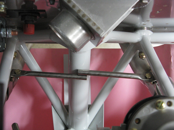
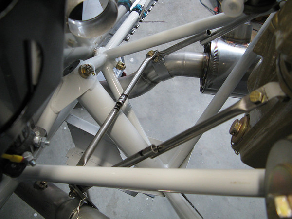
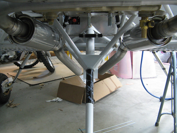
My gap fairing fit was terrible (had to make my own). Yours looks pretty good though! Have you made any more progress towards getting that exhaust hanger figured out?
 
Plan

So my plan is to finish the tail fairing and tail wiring then move to canopy frame then to firewall forward. I figure by mid march I will be there. By that time I am confident others would have figured it out by then, if they havent already. It is wonderful that others have gone before. I am forever grateful for you and others sharing your wisdom. Thank you.
 
So my plan is to finish the tail fairing and tail wiring then move to canopy frame then to firewall forward. I figure by mid march I will be there. By that time I am confident others would have figured it out by then, if they havent already. It is wonderful that others have gone before. I am forever grateful for you and others sharing your wisdom. Thank you.

No problem at all! Glad to see your project is still banging away!
 
Forward fuse top

The forward fuselage of my slider is a little tricky.


There is a slight bend in the sub panel near the bottom; without this, the fit is terrible. I marked the bend, used an 18" brake on the outside, and a block of wood clamped to the table for the center section's bend.

IMG_1712.JPG

.

The center web does not have prepunched holes in either the firewall, nor the web.

There are many ways others have installed this part. Here is what I did:


I first built up the web per the plans. Then I assembled it all together but put the forward skin on one hole back, so I can see to mark the location of the web on the firewall.

I made the holes in the same vertical location as the outside ribs

IMG_1717%25281%2529.JPG


Then I put the skin on properly, drilled the top hole and clecoed.
IMG_1719%25281%2529.JPG


I then removed the skin, aligned the rib to be vertical, and drilled the remaining holes.


Unfortunately, the center brace is now no longer sitting on the firewall angle, so I will make a spacer. I had aligned the angle to the web based on a center line drawn on the angle. I probably should have drilled the rib to firewall first before drilling the angle to the web.

IMG_17222.jpg
 
Tail Wiring

So I am trying real hard to get the turtle deck on the tail. But first I decided I would install the wiring to the tail and the ELT mount; basically as much as I could before covering up the tail section. I really dread the thought of having to crawl in the tail to do systems installation.

So the pitch autopilot servo is in and wired, and the Canbus to the tail mounted GMU11 magnetometer is installed. I also installed a DTM connector in the tail for the electric elevator trim.
Lastly I installed the ELT mount kit from Vans. Of course there was a slight mod so that the mounting hole pattern would fit both of the most popular ELTs.

All that's left is the ELT wiring, and the doubler for the ELT antenna, then I think I can install the tail's top skin, or turtle deck.

Helpful hint: If you are using printed shrink sleeve as wire labels, dont use white, use some color other than the wire color. I spent a lot of time looking for the white labels on white wire.

IMG_1775%25282%2529.JPG


IMG_1776.JPG
 
Last edited:
more cow bell

Walt,
You said add more service loop.
Would you support that larger loop with a pan pole or let it flop around?

I have enough to mate and de-mate, without worrying about it flopping around.

Thanks for the feedback, much appreciated.
 
Calling the Fuse Kit Done

Well, the last lines of the fuselage kit's instructions have been completed; I am calling the fuselage kit done. It doesn't look like much progress, but a ton of work and learning.

I added a doubler for the ELT antenna. It sounds simple, but took longer than expected. Everything else went OK. I had a really good bucking bar helper; I am not sure how anyone could do this riveting alone.
It took me a little less than two years to complete the fuse. Seems for many others, the slow build fuse takes twice as long as the wings. I guess I am no exception to the rule.

I was able to attached the side braces on the bench before installing the turtle deck; I can't image doing this on the plane. Those elevator supports I built several years ago really came in handy.

Next up, the finishing kit, starting with the canopy.

IMG_1810.JPG


IMG_1797.JPG
 
Last edited:
Curved sections

Aha so that is where those curved channels go! I was wondering about them in my parts box as I am not yet that far along on the fuse.
That's a good idea for holding the turtle deck, thanks for posting.
 
Finishing Kit, Part 1 of 100

So it is time to start the finishing kit. First up is the canopy. It seems nothing has caused more trepidation from those who have gone before.

So I dive in.

The roll bar is attached first using special spacers. These have to be drilled to match the holes in the canopy rails. I drilled a pilot hole first, then flipped the spacers over and drilled the final hole from the "backside". I did this to avoid the drill bit wondering due to the "split level" top side.

IMG_1820.JPG


IMG_1823.JPG


The rest of the roll bar install went per plans. I did have to use a 0.025" shim under the left side to get a good fit, as mentioned in the plans.

I started fitting the canopy slider tracks too. I am installing the Supertracks from Flyboys that allows the canopy to open up farther. I order the longer RV 8 track spacer to avoid a split in the track. The trouble I ran into is bending the curve. Turns out using a simple wood block and the Armstrong method, I was able to bend it to match the full size template, no problem.

IMG_1869.JPG


Drawing the center line on the spine spacer was a bit tricky, but I found I could use a carpenters level to draw a line holding the square against one side, then draw another line holding the square against the other side of the piece. This produces two lines on the part, with the exact center being between the two lines. In the picture below you can see the longer spine spacer, and looking closely, you can see the double line markings.

IMG_1871.JPG


Things are slowing down now that the beach is open. But I can't let summer get in the way (too much) so I am determined to keep on making progress everyday.
 
Finishing Kit, Canopy Part 1a

So I have been working on the fitting the canopy frame, the first step on the canopy tasks. I had taken a month off to do yard work and whatever else I could find to avoid the canopy stuff. Finally I decided it needed to get done while the weather was warm.

The canopy frame was fairly close to perfect from the factory. I had to tweak 6 spots in the front hoop. I have a little more to go in the back hoop. But the back hoop requires less force and is already really close.

I took the advice of others and will cut the canopy front tubes, and will put the canopy track on after the frame is bent. I found it was much easier to do this without the tracks being on; I just used a wooden spacer under the front tubes to raise the canopy frame up to about the right spot.

Here is how I bent the front hoop use a 3/4" conduit bender from the precision tool isle at Lowe's:

IMG_1924%25283%2529.JPG


I then measured the height of the gap to make sure each side was even. I found I had to take out a slight bend on one side to make it even.

IMG_1923%25286%2529.JPG


Here is the overall fit of the frame. The top height is not correct because the frame has not been sized for the track rollers.

IMG_1925.JPG


Like everything else on this build, I stressed over this, but once I got into it, it wasn't so bad. Just keep swimming- Dora

I truly want to thank all those others who have come before and posted their build details. It takes the VAF community to keep me on the right path.
 
Last edited:
Looks good John. You also seem to have gotten through that part in better spirits than I did. haha bending and tweaking that frame was probably the worst thing I have done all build so far.
 
Most excellent work on the frame! Mine was pretty close at the outset as well. Like the use of the conduit bender.
 
Canopy, Part 1b

So, today was a good day. I managed to wrestle the canopy frame into submission and I think it fits well. In total, I think a good 8 hours with a 1/2" and 3/4" conduit bender should be a reasonable time to allocate for this task.

I started with the front hoop, and then did the rear hoop today. The rear hoop requires much less force; I over bent and had to unbend several times. My only advice is to realize the levelness of the top horizontal portion is caused by the side bends. The front hoop and the side rails form a rigid structure that the rear hoop bends around. The original fit of the rear hoop was really close, I just had to do a minor tweak. I did the tweak and the shape of the rear hoop became a disaster. I freaked out for about a minute and did the opposite of what I thought it needed and it all came back in line. I used reverse psychology and the metal tubes fell for it. Gosh I am good.

In summary, I started with the side rails (no adjustment needed), did the front hoop, and then the rear hoop. I think this order worked out well.

I used wedges under the side tubes and that was good. This allowed me to put on, and take off, the canopy frame all day as I adjusted the bends.

I am saying it is done. I will check the dimensions and fit tomorrow just to be sure it hasn't decided to spite me and regress to its prior mental state.

Here is a picture showing the wedges I used. I could not imagine doing this with the tracks in place.

IMG_2100.JPG


I will install the tracks next and then onto the big cut.

This summer,
the hardest part of the build seems to be.... summer. Too many beaches to visit and too many hikes to take with friends, but we'll get through it.
 
Back
Top