What's new
Van's Air Force

Don't miss anything! Register now for full access to the definitive RV support community.

RV7 QB bay area

agent4573

Well Known Member
RV7 QB - Paul and Kacy - Bay Area

Issues with the instructions/drawings:

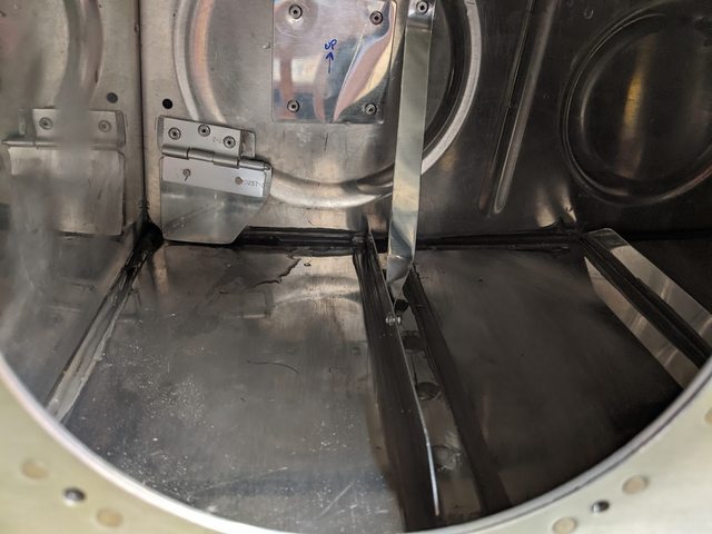
-Page 7-9 says "QB note, see DWG14A Section B-B". This is in reference to the flap brace install with pop rivets. There is no note in Section B-B and the only rivet referenced in that section is the LP4. The note is in quadrant E-6 of that drawing and specifies structural steel rivets. Don't be like me and have to drill out every single flap brace rivet.

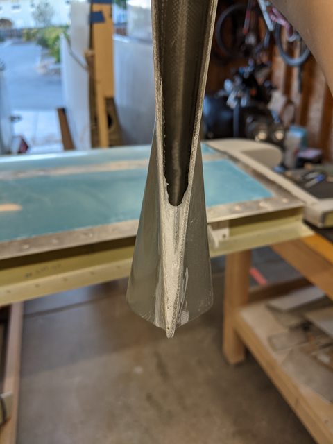
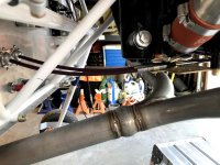
-W716/W818 Aileron pushrod tube length is too short on the drawing. After calling Van's, the numbers on his drawing didn't match the numbers on my drawing, even though we had the same revision and my info packet is less than a month old. The overall length callout seems to be correct, but the call out for how long to cut the tube is about an inch too short. I only had 1 thread engaged.

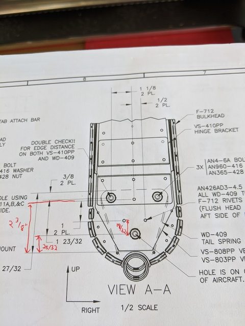
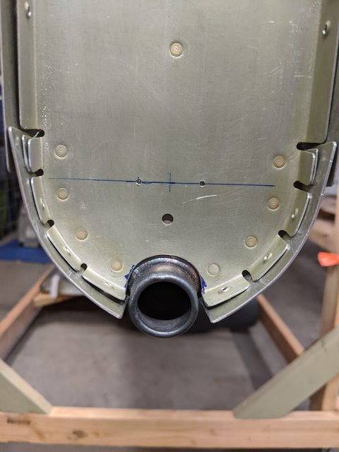
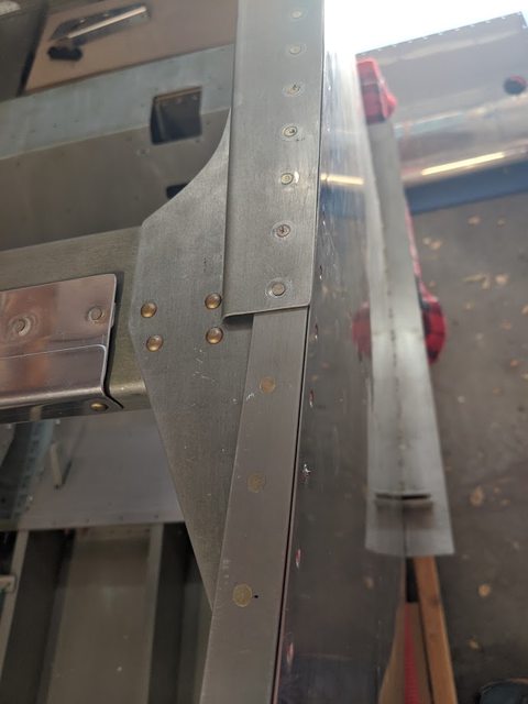
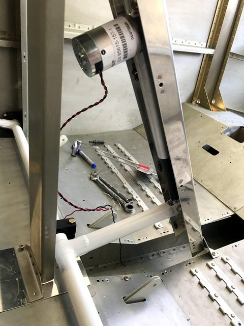
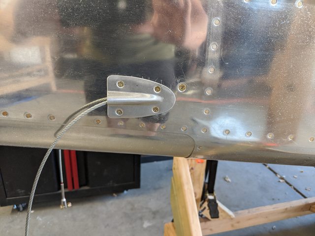
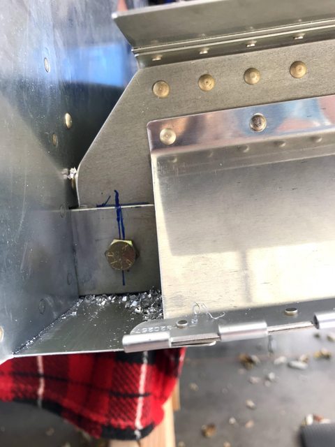
-When installing the tailwheel mount, the "keeper rivets" are referenced to a point that only exists on the vertical stab. I was told to get my vertical out of storage, temporarily install it, and then measure off that in order to drill 2 rivets that really aren't required for a quick build kit. If you're attempting to drill these 2 holes without installing your tail, the measurement you're looking for is 19/32 up from the tooling hole. There's a post with a picture if you want more info.

-Page 8-7 says "Notch longeron around 711-C per DWG 18". It should point you to drawing 27A.

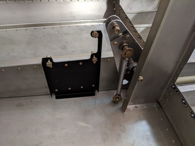
Section 8-9 Brake assembly. The drawing was updated almost 20 years with revision 1 that changes the bolt length call out from an AN3-4 to an AN3-5 for the "skinnier" side of the brake pedal. The "dual brake kit" still provides you with AN3-4 bolts for the passenger side. The quickbuild kit provides AN3-5 bolts for the pilot side. So 20 years after updating the drawing, they haven't updated the BOM for the parts. Also, an AN3-5 bolt will require the maximum 3 washers in order to get the length correct.

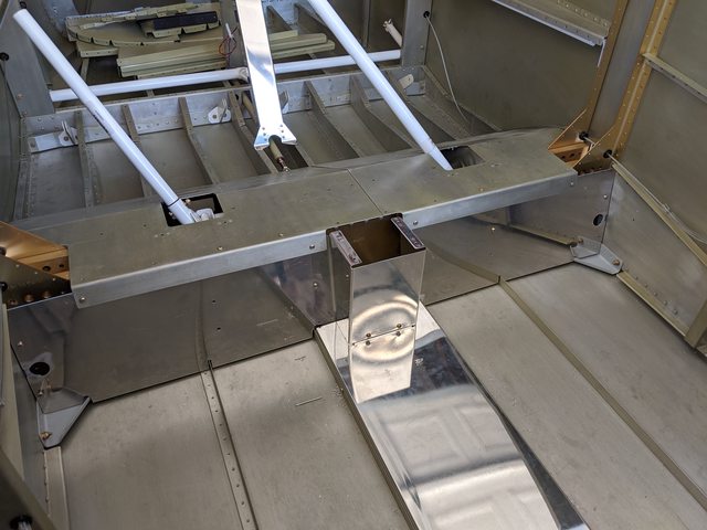
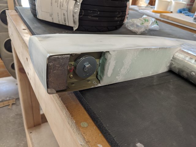
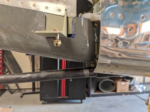
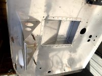
Section 8-9 Making F769-B angle support for the fuel tank mount. Drawing 38 detail F calls out a countersunk screw, washer and nut for the lower mount. Drawing 28 calls out an AN426AD4-6 rivet in that spot. Van's helpline says the screw and nut is the proper hardware.

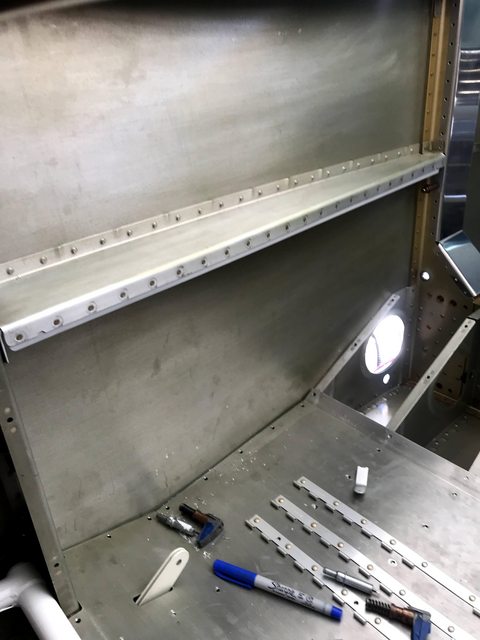
For quickbuild kits, the half round pieces that hold F786 J stiffeners in place should not be used when drilling to the skin. Remove them, line everything up and then drill. I assumed they were jigs to hold the stiffeners in the correct location and now I have zero edge distance on the front of those stiffeners. To fix it completely would require drilling out the entire stiffener from the already complete aft upper skin and redoing it. Helpline said I would be fine with one or two having 0.020 edge distance, so I'm torn on fixing it correctly, or possibly adding in a doubler because I assumed extra pieces added to the kit would be helpful and not hurtful.

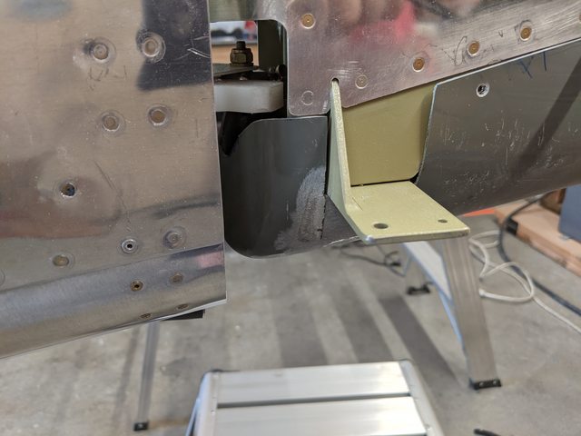
Section 8-11: "Remove the clecoes on the right side of the F-774 (7112) and F-775 skins and lift them up to expose the F-787 stiffener rib. Fabricate the F-707B clip shown on DWG 26. Clamp it to the F-707 bulkhead and F-787 rib. Drill it to the F-707 bulkhead using the pre-punched holes as a guide. When it is clecoed to the bulkhead, drill it to the rib. You may rivet F-707B to F-787, but do not rivet F-707 until the aft top skins are riveted – F-787/F-707B blocks
access to one of the skin rivets." For quick build people, the rivets it tells you not to install come pre-installed. They're a pain to drill out because you can't get a straight shot at them too, so enjoy oversized oval holes when you drill them out in order to be able to rivet the skin on.

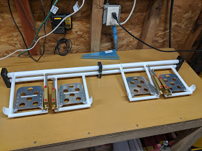
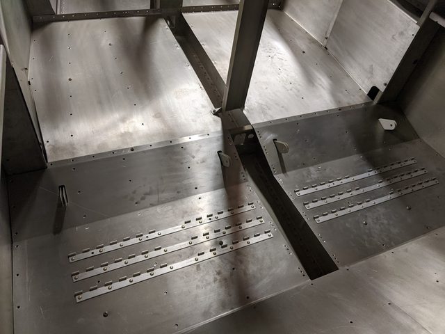
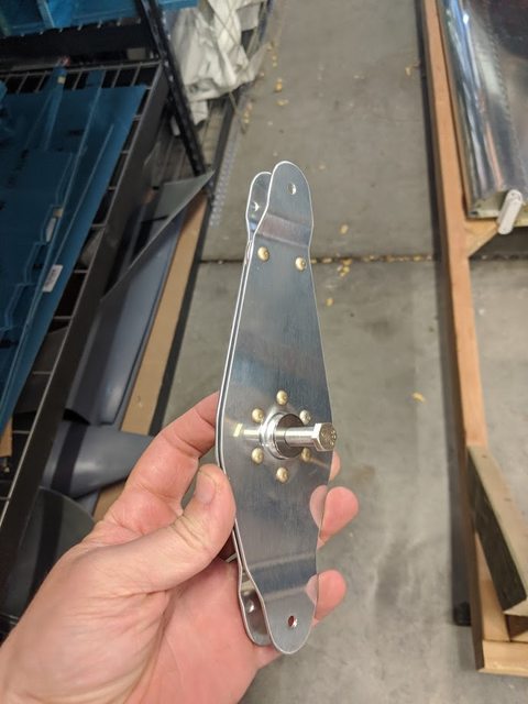
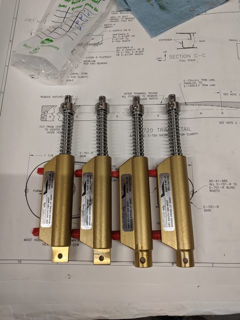
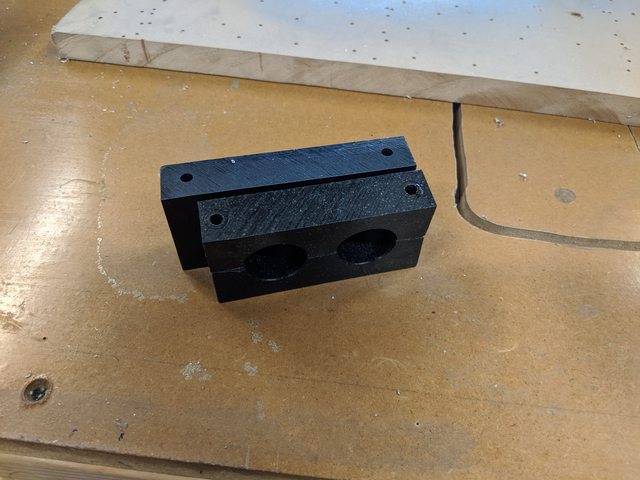
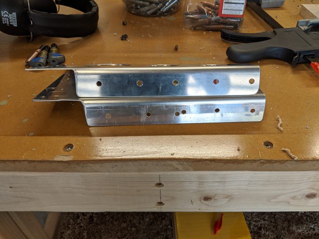
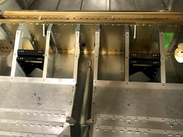
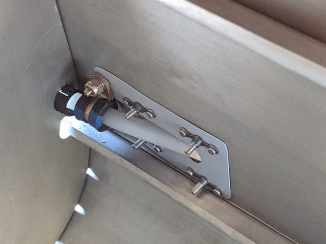
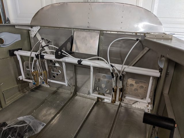
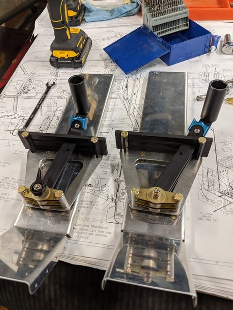
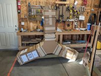
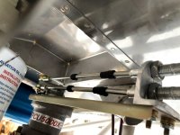
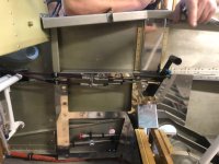
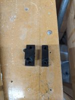
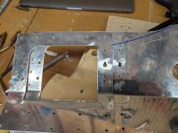
Rudder/Brake pedals: The center pedal support is 0.5" shorter than the side supports. When I drilled my adjustments for the side supports I used the spacing of the bolts as my adjustment, so the front bolt in one location became the rear bolt for the next adjustment. This worked fine until I attempted to drill the center support bracket. Doing this spacing means you'll have holes 1/4" apart from each other in the center because of course that bracket couldn't be the same length. I ordered another side mount bearing block and a new center support bracket. I'll open it up so it isn't closed on one side. This will allow me to have the same center adjustment spacing as the sides I've already drilled.


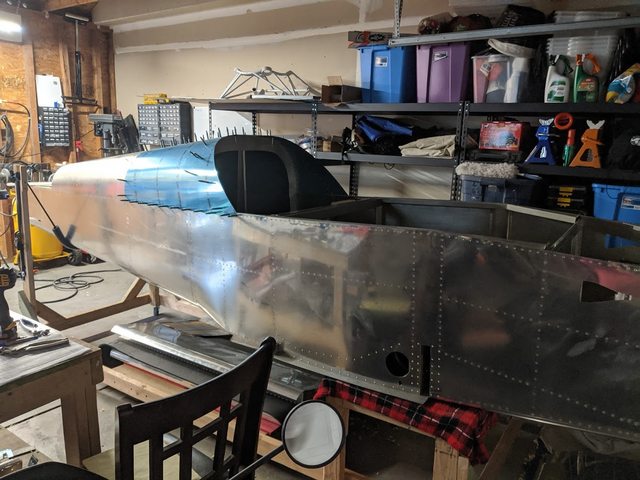
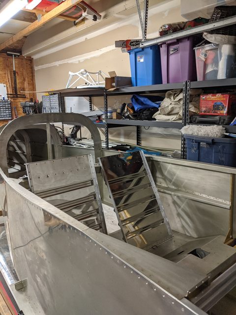
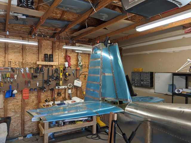
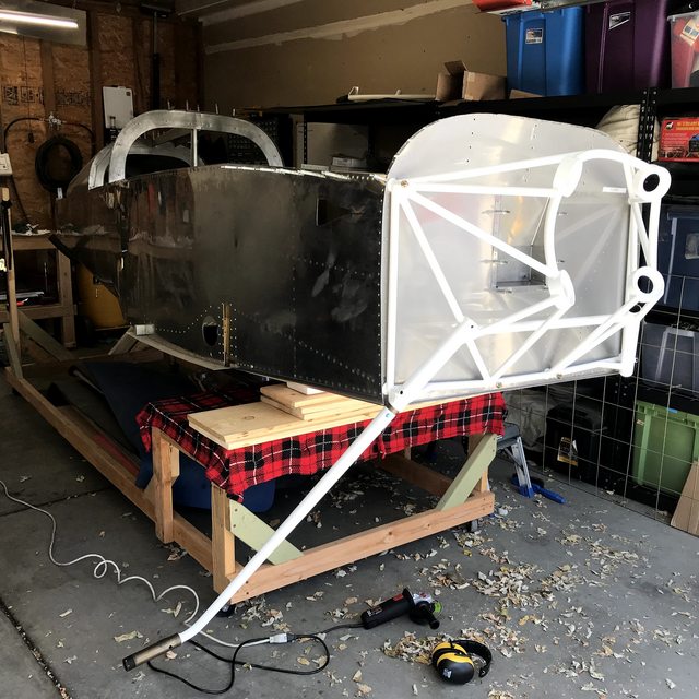
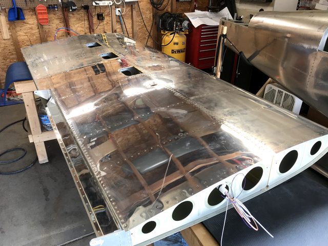
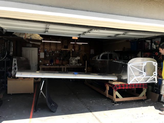
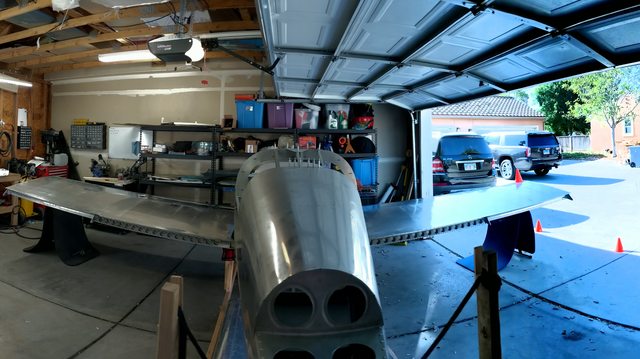
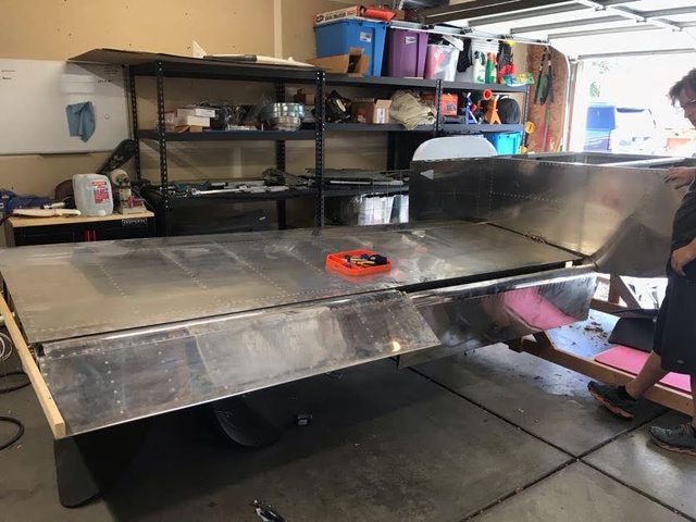
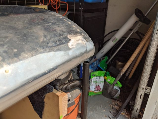
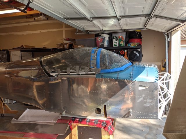
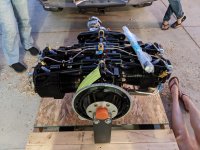
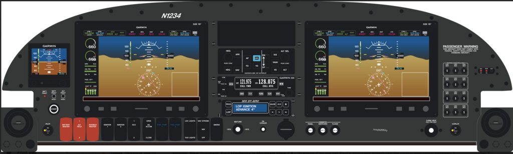
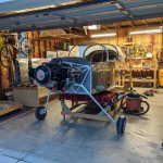
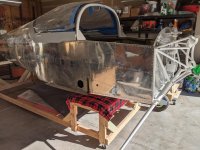
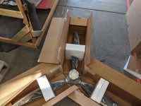
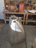
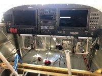
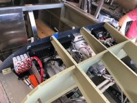
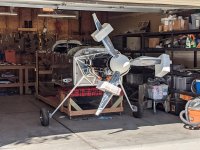
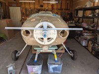
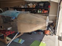
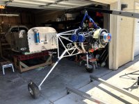
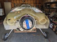
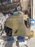
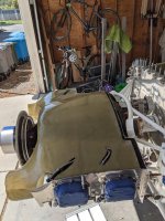
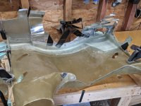
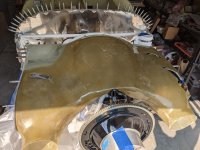
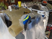
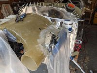
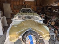
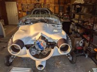
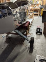
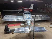
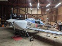
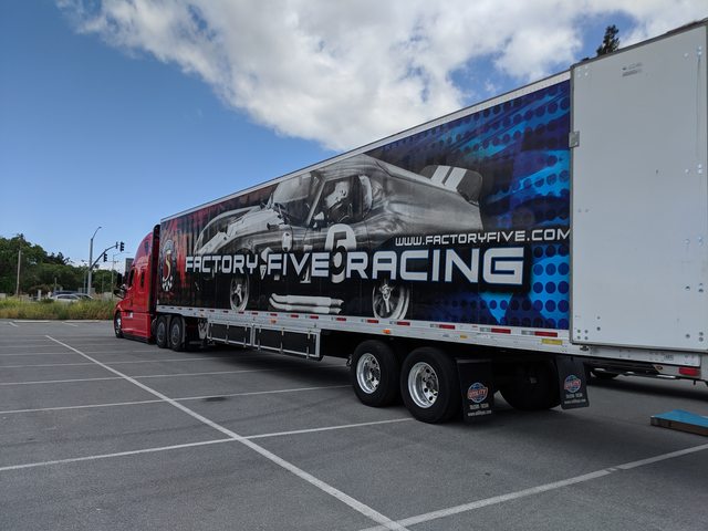
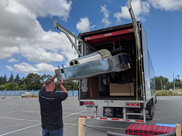
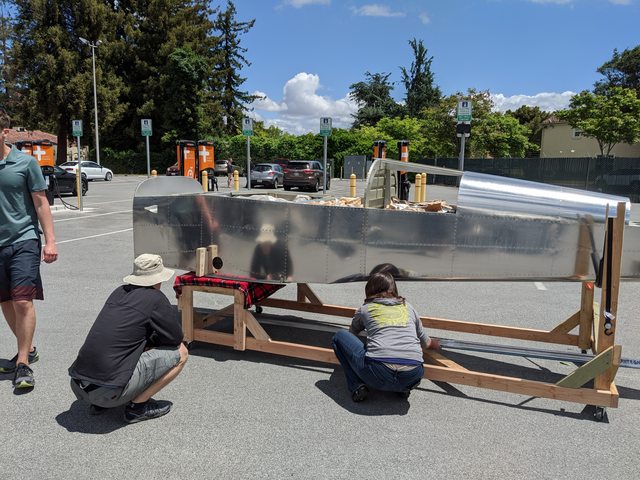
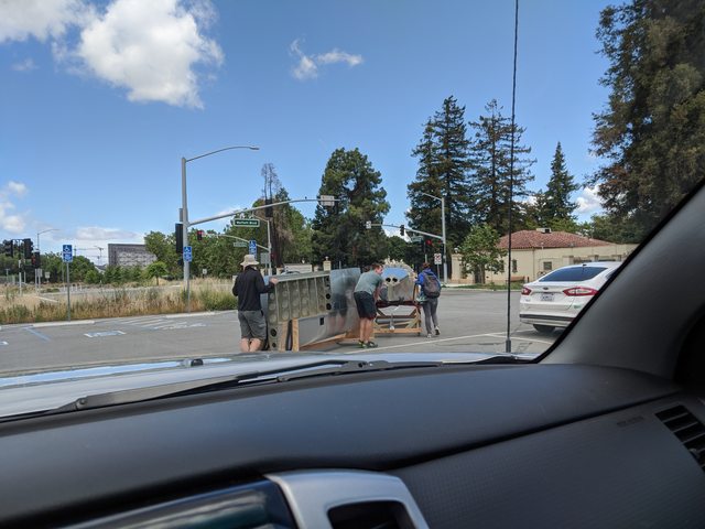
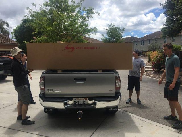
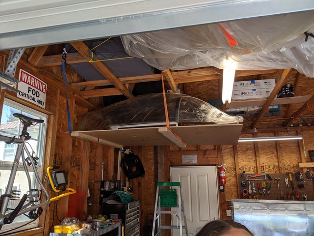
Held off on posting this because doing the tail kit didn't feel like I was actually building yet. Took delivery of the QB fuse, wings and finish kit today, so I guess it's real now. Plan is an aerosport 375 with SDS fuel and ignition, dual g3x panel, smoke, etc. The blog link is in my signature for empannage build details. Today was unboxing and trying to find a spot to put the massive amount of packing paper they include. Tomorrow is inventory. The goal is to fly this to Oshkosh 2022.

YeNUS0Kl.jpg

drgspfel.jpg

r4tpIPWl.jpg

ht1aIoxl.jpg

ZiTBrMll.jpg

cIcptWyl.jpg
 
Last edited:
Made some progress in the last week. Inventory is compete and we're only missing a few minor nuts and bolts. Got to work on the tanks and they're ready to be closed up. Working on the wings now and will have the ailerons and flaps ready to go on by this weekend hopefully. Put an order into vans for some tank sealant and closeout plate for the inverted tank closeout. Talked with our panel guy and he's gonna get the gap 26 aoa probe and the wing harnesses made up and sent out. Got to put in order into spruce for the wingtip lights, nav antenna and other misc things before closing out the wing. Had an interview today and a follow-up in a few days, so 8 hour days may be in short supply for the plane, but if I get the job I can put the engine on order. We realized we were over a month behind on the blog, so we made a few posts tonight and should hopefully be caught up by the weekend. Check it out.

OLQJxcil.jpg

OXvN6lKl.jpg

XqgR3FKl.jpg

jGPUrwjl.jpg
 
Last edited:
So the blogs only a few weeks behind now instead of months, so go check that out for more pictures and progress. Here's some of my highlights. Its nice to be unemployed right now, because I can dump 6-9 hours a day into building this thing.

Since the last post, we finished up 90% of the fuel tanks. We're planning on an SDS fuel/ignition system, so we added an AN6 return line to the tank. It dumps onto the "bottom" skin just aft of the stiffener behind the pickup. It meets the 4" recommended separation from Van's and shouldn't foam since its 1/8" off the skin. The left tank was already off so we pressure tested that one first and it seems to be good. I sprayed a whole lot of soapy water around that thing and couldn't find any bubbles. The right tank will have to come off next since the main wing spar wasn't deburred well where the tank Z brackets mount. We'll need access to clean those up. When installing the barn door in your upside-downable tank, make sure your rivet squeezers have enough room to reset if the rivet doesn't pop. Lesson learned and they were cheap squeezers, but having to take a cutoff wheel all around a steel tool stuck inside your tank is not a fun morning.

NkgKt4Dl.jpg

LGB7bkBl.jpg

6C2LUhWl.jpg

KPGqstcl.jpg


Installed the tailwheel mount, which included cutting away some skin and making some shims. It ended up taking 0.100" shims in order to get the rear faces to sit flat with each other. The "keeper rivets" they tell you to drill are dimensioned off of parts that don't exist yet, so unless you want install your tail just so you can drill these 2 holes, the dimension you're looking for is 19/32" up from the tooling hole. Also, the tailwheel is 20% gloss exterior powder coat. It looks pretty good, so we'll likely get the rest of the pieces done to match that.

FH8w1Nhl.jpg

4PVtH9ol.jpg

1ILvAnbl.jpg


Got the pedals rivetted up and bolted together. If you torque the bolts to the recommended values, the pedals don't move at all. These will be literally finger tight and the cotter pin installed. There was some issues with the spacing when drilling the adjustment holes. The center support is 0.5" shorter than the end supports, so you have to be extremely careful with hole spacing or things start to overlap by half a hole. I ended up ordering another end support and will drill it out to fit in the middle of the bars. Then I'll be able to use the same spacing in the center as the sides.

wH5dufI.jpg
 
Ran out of room for pictures.... Here's the second half of the post.

Besides that, I've just been working through the instructions. I got the elevator push tube bell crank made up, got the forward top skin cleco'd on and match drilled. I ended up getting all the sub-structure deburred and dimpled, but still have to finish all the prep work on the skin itself. We wanted to be able to remove the floors during annual inspections so we opted to not rivet them in place. I spent 2 days installing over 100 nut plates before running out. There's more on order from spruce and I have about 25 to go. I keep telling myself it'll be worth it in the end. I also got some of the center rail brackets cut into shape for the slider canopy. Spent some time installing some basic wiring in the wings and got the GAP28 autopilot servo installed. Waiting on some wire and connectors so we can get that closed out. Put the mount plate in for the GAP26 AoA probe in as well and got the stall warner mounted up. Wasn't sure about doing both the AoA probe and the warner, but extra things telling you you're about to crash are probably a good thing.

R4ro0cbl.jpg

OoJwlwYl.jpg

WFkvtF7l.jpg

1Uu35bzl.jpg


Future plans are to get the skin installed and start work on the tunnel covers and seat backs. Still gotta pull the right tank for a pressure test and to clean up the spar holes for the tank mounts. The left side needed a ton of deburring, so I assume the right side is just as bad.

Also, WE PUT OUR DEPOSIT DOWN ON THE MOTOR!!! We decided to go with an Aero Sport Performance IO-375 200HP with a whole bunch of go-fast goodies added on. I'll make a separate post about that with all the details. It's probably a little early, but its 8 weeks build time and that's a long time for progress when I'm not going into work right now.
 
Are you sure you have the right material for the seat back brace in your photo above?

That radiused sheet metal looks quite a bit thinner than the angle stock on mine unless you radiused the rear edge for some reason, just curious.
 
Are you sure you have the right material for the seat back brace in your photo above?

That radiused sheet metal looks quite a bit thinner than the angle stock on mine unless you radiused the rear edge for some reason, just curious.

It's 0.040 prebent sheet vs. the 0.060 angle the plans calls for. I like the look of it a lot better than the angle. All the load goes through the rivets in shear on the flat piece and the spacer so the extra strength shouldn't be needed from the thicker angle. It's also in a really easy to access spot so if there's any issues with it, I can easily replace it with the angle.

EDIT: was building the seat backs today and realized I need to swap out those angles. The back brace goes between the pieces, not under the flat piece like I thought. So I'll drill out those angles and replace with the .063 angle and keep pressing. Good catch.
 
Last edited:
Been a while, so here's a few updates. More details can be found on the blog.

Added the spring returns to the rudder pedals so I don't have to worry about accidentally dragging brakes during taxi.

bjpJ1YZl.jpg


Got the seats made up and installed. Gonna leave these as bare aluminum since they'll be covered all the time anyway.

ykQI38kl.jpg


Installed the GAP28 autopilot servo from garmin. This thing went in so easy its ridiculous.

zN69Zgbl.jpg


Cut the hole out of the bottom skin and installed the mast for the GAP26 heated pitot probe. Also installed the stall warner system on the leading edge.

RPSO5Dgl.jpg


When doing the center rudder pedal brace I found that the center plastic block was 1/2" shorter than the outer blocks. This means really poorly offset mount holes on the aluminum brace. I ordered an extra side block and a new center brace. I drilled out the extra side block so it fit in the middle and now I could use the exact same mount holes as the actual side blocks.

9XvZhV1l.jpg

gXJKDy4l.jpg
 
Installed the tail and got the elevator and push rods rigged up. Installed the internal rudder stop (took 2 tries to get it right). Drilled the hole on the side of the elevator for the electric trim servo.

6kPiJr3l.jpg

J3LKHAYl.jpg


Installed the submarine seatbelt mounts.

59qXK96l.jpg


Got all the forward cockpit covers in place. Waiting on the Andair fuel valve before I make up the fuel lines, and I'll have to make a center cover becasue I have to mount dual electric fuel pumps plus a pre and post filter on the floor in the cockpit. This is all to support the SDS EFi system that's going in.

tBZXYr3l.jpg


Reinforced the armrests. They sit a little taller now, but are so much stronger. We're doing dual side mounted throttle quadrants, so we'll need the armrests to support the weight of those plus your arm. More updates later on how I link the two quadrants together so they work in sync. Flyboys was nice enough to work with DJM, and the timing worked out, for us to get 2 lever (throttle/prop) quadrants in a left and a right setup. I don't have them yet, but I have an idea how this is all going to work together and I think its gonna come out sleek.

0GdTS1el.jpg


Installed all the electric flap linkages and motor.

gg8FqSHl.jpg


Bought the rudder cable fairings from spruce and made them look nice. Made up some backing plates that are held in place by the screw and adel clamp that holds the plastic tubing on the rudder cables. Now these are easily removable with just a screw driver from the outside.

C2dkYPpl.jpg

TMJSK21l.jpg
 
Installed the engine mount and test fit both the landing gear legs. The instructions say installing these "can't be easier", except they don't actually fit all the way in, so there's going to be some light sanding and polishing so i can actually get the round peg to fit in the round hole.

IkFxVuOl.jpg


Bucked on both bottom wing skins and got them ready for assembly with the fuse.

kDKhipRl.jpg


We test fit one wing at a time to make sure everything lined up. To do this we used the hardware store bolts that I ground down to make some drift pins. The wings go on/off in about 5 minutes with no issues. After we test fit individually, we started one morning early, mounted both wings and worked on getting everything straight so we could drill the rear mount hole. The width between the blue lines is the margin of error for putting the rear bolt in and keeping the required edge distance. They don't give you much extra material back there. In the end we ended up with 0 sweep, 0.9 degrees of incidence on both wings (to help make the flap skins sit flush against the bottom of the fuse), and 1/16" out of square between the left and right wing when measured to a common spot on the fuse.

jY31XUCl.jpg

ThsVUXhl.jpg

czMkeejl.jpg

BNWHuJll.jpg


Once the rear mounts were drilled/reamed to final size, we took the right wing off and now I'm doing the minor work on the left side. We mounted the aileron and rigged everything up so its all in trail with the sticks in the neutral position. Installed the elevator up stop and gave ourselves 30.5 degrees of travel. Van's allows between 25 and 32 degrees.

bWoWdhXl.jpg


We hung the flap as the last thing today. Immediate future work will be drilling through the fuse floor to rig the left flap and make sure everything moves freely. I've gotta do some research on how to run the fuel lines with the inverted pick-up and I have to make up the circular vent tubing and install the wing root fairing.

fyfKeaOl.jpg
 
Did you try putting the struts in a bucket of ice. Just need to put the top in for an hour or two. Thay should slip right in.
Hope this helps.
 
Did you try putting the struts in a bucket of ice. Just need to put the top in for an hour or two. Thay should slip right in.
Hope this helps.

I'll likely do that for final assembly. I didn't want to get them in there right now and not be able to take em back out. Not quite ready to have to work around the gear legs from here on out.
 
Disaster!

I was relocating the wiring conduit in the right wing and while moving the wing around the garage, it slid off the stand and dented the front skin pretty bad. An A&P buddy came by and said it might be salvageable, or at least worth trying to form it back into shape. He did say if it cracked during reforming to just go ahead and build a new tank. So this might be a waste of paying for a quickbuild wing set when I have to go back and redo the messy part anyway. It appears to have missed the rib, but it got both sides of it.

GIWBz8Gl.jpg

7Y4hQPvl.jpg
 
Last edited:
A few more updates....

Here is the aftermath of the wing work. I had to pull the access panel off to get to the backside of the dent. I made up some wooden dowels and put them on the rivet gun in order to get the muscle power to knock the dent out. Can't get to all of it without ripping all the sealant out of tank, so this is its final form until we go to paint and will cover the rest with the proper bondo/epoxy that the painter recommends.

DNYwxCkl.jpg


Got the brake lines in and routed for the cockpit side.

ML5g2fGl.jpg


Still waiting on the andair fuel valve I ordered over 2 months ago, so there's still no fuel lines. That's kind of disappointing, but we moved on to other work. The throttle quadrants and lights came in from flyboys so we installed both of those.

KYf2bSwl.jpg

tYkO3VFl.jpg

OUTpALYl.jpg


Cut the flap position holes and installed the flap position sensor.
9eo3qEZl.jpg

IsPJzNQl.jpg


Got the pitch autopilot servo mount installed. Can't afford the actual servo yet, but at least I can get the metalwork done.
MftNHlAl.jpg
 
Laid out the rivet locations for the Titanium belly skin. It an 20x24" piece of 0.020 Ti bought from Mcmaster. It has 1/8" of Fiberfrax sandwiched between it and the primered skin. I made 2 drain slots on the rear of it for any water to drain out, but it sits so well against the belly skin that I'm not planning on sealing the edges or worrying about water ingress.

25jIOLkl.jpg

VxxLPW1l.jpg

LYjotOZl.jpg

2GiwIHol.jpg

OKDCDDTl.jpg


I've got 50 hours into shaping the canopy frame and trimming plexiglass at this point, and I figure I'm about halfway to being ready to glue everything together. The rest of this week will be spent doing final trimming and adjusting and hopefully I can glue it all together Friday or Saturday.

J3eXDeEl.jpg

xVFO9gjl.jpg

YCy63sxl.jpg

ddS2uKyl.jpg

YAHyOJZl.jpg


Engine gets shipped on tomorrow, so hopefully it will be here by this weekend or early next week. Time to move on to firewall forward work.
 
Engine is here!!! Also, the canopy is glued and curing.
 

Attachments

  • PXL_20201014_015114425.jpg
    PXL_20201014_015114425.jpg
    477.2 KB · Views: 398
  • PXL_20201011_215744691.jpg
    PXL_20201011_215744691.jpg
    453 KB · Views: 395
Last edited:
Been doing a whole lot of fiberglass work lately. I have zero previous experience with glass work, so this all took me way longer than it should have. Started with the horizontal stabs and elevators. Used the method from stu's aircraft factory of filling in the gap with some foam and then floxing it in before covering with micro and doing the final finish. I riveted the caps in place, then filled the small gap with some micro. After that got sanded I laid up a layer of glass and then more micro and high build primer. I'm not talented enough with paint prep to get these 100%, so I'm getting it to the high build primer point and calling it good enough to go to paint. I'll pay a professional to do the final body work on it before spraying it.

63nBvYMl.jpg

ESFx9ivl.jpg


The left elevator was way under-balanced since I put the electric trim servo in, so I had to take care of that. I added a 4AN nutplate before I put the cap on and then closed out all the surfaces I could. Since it as 90% done now, I added washers until it was slightly over-balanced and then covered up all the washers with flox. This should get me close and after paint I can drill out some of the lead counterweight to get me a perfect balance.

GRThvbAl.jpg

PH9MNXxl.jpg

Jl89P13l.jpg


Once the horizontal tail surfaces were done I moved on to the vertical and rudder. I decided to make the lower cap removable because I don't like having anything behind unremovable panels (tail light and wiring). After cutting it to clear the tail spring I didn't like the large gap.

z2Nyd2Sl.jpg


So I cut the front cap off, removed 1/4" of material, and then glassed the two pieces back together. There was also an area near the rear that protruded out from the skin. While I was floxing in the FlyLED taillight mount ring, I filled in the last 1" or so of the cap. This allowed me to sand off the protruding section of fiberglass and now everything fits nice and smooth.

7GtFF3vl.jpg

mXOwbTxl.jpg
 
After the lower cap was done I moved on to the top of the rudder and vertical. These were in no way aligned and I really didn't like the look. After some suggestions in another thread that leaned away from just filling in 1/2" of micro and sanding, I ended up having to cut and reglass it into a closer shape. After that, it was closed out and then covered with micro and sanded into a better matching shape. It got more final sanding and some primer, but the pictures show how the shape took a major change.

mZX1mdVl.jpg

1EZ0RUjl.jpg

gytN9uTl.jpg


So now it was time to fit the empannage fairing, and the supplied van's fairing just fit like ****. It took two of us to pull it into position, and even after that, there were areas with 1/8" - 1/4" gaps between the skin and fairing. We decided to toss it and make our own.

jrsgbYSl.jpg

Yyjj3qdl.jpg

tYd4ghQl.jpg

Qb1WMiBl.jpg


It still needs more sanding, but it fits a hundred times better than the supplied one. I ended up trimming the side skirts to the canopy before setting the final height, and that turned out to be a bad idea. Between the gaps I made up front, and the extra width I had in my canopy frame in order to let it open/close without catching the turtledeck skins, I'm basically backed into the corner of doing a fiberglass canopy skirt as well. So I started that....

QqGKWxVl.jpg


Hopefully I can finish up the fiberglass work by the end of the year and move on to other things. I put the deposit down on the avionics panel today. We went with Aerotronics for the panel build. Our build slot is January, so I have a 2 months to finish fiberglass and get the engine hung and plumbed. I also got on sam james build list back in February and got word last week that the cowl, air box, and plenum were ready to ship. Hoping to have that here as early Xmas present to myself. Placed a bunch of orders with spruce for antennas, smoke system, oil accumulator, oil cooler and mounts, etc. Also got with TS flight lines and ordered stainless brake lines and all my fuel lines so I can get the pump and selector in and plumbed.

5EwBP6Eh.png
 
Last edited:
Great pictures! Regarding the empennage fairing: Is it one piece or did you also make a piece that goes below the horizontal stabilizer?

I'm about where you are with the build (just starting to work on the engine) and am up in Livermore. If you ever want to get out to the boonies for a bit and check out the project, more than happy to show it.
 
I just did the upper piece. It wouldn't have been hard to do the lower as well, but the metal lowers fit pretty well after a trim, and I don't think I'll take them off the plane except for paint. The tail can be installed/removed with the lowers in place.

I'd like to take a look at your setup. PM sent with some contact details.
 
Finished up the canopy fairing. Like the rest of my fiberglass, it's not perfect, but it fits great and is plenty good to go to the painters. I also got the main gear on and hung the engine. The instructions for the gear are a single line that basically say "this can't be easier, tube goes in hole and a single bolt". After some blow torches and ice bath, lots of sanding, making a drift pin and bending said drift pin with a 4lb dead blow, and hours of fighting it, the gear went in. Great job on the instructions vans....
 

Attachments

  • IMG_20201230_173855_449.jpg
    IMG_20201230_173855_449.jpg
    625.7 KB · Views: 647
  • PXL_20201230_203536565.jpg
    PXL_20201230_203536565.jpg
    416.2 KB · Views: 517
So after months of waiting for parts, things started happening very quickly. I've been on hold since December waiting for a cowl from Sam James that was supposed to arrive in November. The moderators will not let me go into any details about this. What I will attempt to say, is that the new owner of Sam James cowling (Mona) has been a pleasure to work with and is extremely accommodating and customer focussed. The old owners I'm not allowed to talk about. Skipping ahead.....

Last week the panel showed up from Aerotronics. With only very minor trimming of the lower panel brackets, a hole for the radio and GNX375, and minor trimming of the center vertical to clear the AP control head, the panel bolted in. Now the only thing left is to wire the rest of the plane. Minor detail.

Next is the box with the cowl in it. The quality of it looks really good. Not sure how much final work will be to fit it, but I'm looking forward to getting it on the plane. I also got their plenum and FAB for the full setup. The alignment tool is in the mail from Blake at Flyboy accessories. I ended up buying the tool, so if you need one in the bay area later this year, shoot me a PM. I was planning on getting with the local EAA chapter and letting them borrow it long term once I was finished with it.

And finally, we have a delivery from Whirlwind Aviation. Here is a brand new 300-72 prop. Saber delivered the 2.5" CS extension a few weeks ago and I think everything is finally here to get a majority of the FWF finished.

In my downtime I started training for my IFR ticket. My checkride is scheduled for May 1st, and after that I'll be diving back into this build hard.
 

Attachments

  • PXL_20210415_002503211.jpg
    PXL_20210415_002503211.jpg
    468.3 KB · Views: 442
  • PXL_20210415_002806324.jpg
    PXL_20210415_002806324.jpg
    295.8 KB · Views: 434
  • PXL_20210415_003550126.jpg
    PXL_20210415_003550126.jpg
    365.6 KB · Views: 544
  • IMG_0177.jpg
    IMG_0177.jpg
    83 KB · Views: 519
  • IMG_0178.jpg
    IMG_0178.jpg
    88.6 KB · Views: 489
Last edited:
I've been waiting on my James cowl for quite some time. Mona called a couple of days ago, she is very helpful and they may be light at the end of the tunnel for me soon. I was getting very concerned as I bought the extended hub Hartzell CS prop specifically for that cowl... a expensive piece of kit and a special order M2YR. My M1B TB engine arrives by EOM (I'm told) and then I will want the cowl to start fitting it to the fuselage, prop, spinner.

Was your cowl a product of the new/current James team?
 
The cowl I ended up receiving came from Mona and the team in Texas. Yeah, that extended hub prop really locks you into using their cowl. Hopefully she gets you one soon. I know for a fact there's an extra RV7 long cowl sitting in a shipping dock in maryland right now. If you're next in line it may be available sooner than you think.

When she first took over earlier this year she was waiting on some back ordered material before she could even start manufacturing. I'm sure they're doing what they can to catch up, but she was on pause for at least 2 months waiting for supplies. I think my original order for the cowl was placed february or march of last year.
 
Sitting here at Oshkosh with some down time and figured I'd write a mobile update. Got the cowl done, but not without a lot of finish work. I used the cowl alignment tool, followed Sam James instructions and still managed to have a 1/2" gap across the front when I removed the tool. I did get to test fit the prop just to verify the distance to set the tool, so that was a happy day. I went back and added a flange and some flox to close the gap up and it looks good. We went with the skybolt fasteners and I started off by dimpling the flanges instead of countersinking them. Since everything had been match drilled by that time, I decided to make spacers instead of ordering new flanges, so I now have 50+ .063 spacers as reinforcements on my cowl mounts. Beyond that it was filling and sanding, rinse and repeat. Got the cowl in primer just before we headed out to Oshkosh on the 16th. We went with the spring loaded oil door hinge and glassed in all the cowl and door rivets with a layer of fabric and then micro. We're running a plenum for cooling, so I didn't feel the need to reinforce the quarter turn line or the oil door for strength. If we were using the standard baffle kit, I likely would have put a layer or 2 of carbon inside the oil door and along the fastener line.
 

Attachments

  • PXL_20210504_230144973.jpg
    PXL_20210504_230144973.jpg
    433.2 KB · Views: 414
  • PXL_20210508_181508631.jpg
    PXL_20210508_181508631.jpg
    382.7 KB · Views: 358
  • PXL_20210523_214821918.jpg
    PXL_20210523_214821918.jpg
    389.9 KB · Views: 398
  • PXL_20210615_042903980.jpg
    PXL_20210615_042903980.jpg
    306.7 KB · Views: 393
  • IMG_20210702_134227_756.jpg
    IMG_20210702_134227_756.jpg
    86 KB · Views: 429
  • IMG_20210710_161346_753.jpg
    IMG_20210710_161346_753.jpg
    205.5 KB · Views: 426
  • PXL_20210623_044921085.jpg
    PXL_20210623_044921085.jpg
    210.3 KB · Views: 428
  • PXL_20210702_195215022.jpg
    PXL_20210702_195215022.jpg
    347.4 KB · Views: 379
Last edited:
Along with the cowl, we've been working on adding extra fire protection to the firewall. We went with 1/8th fiberfrax and .005 stainless sheet with firebarrier 2000 to seal the edges. I added plate nuts for most of the things that might have to come off more than once, and made a tray to mount the 2 gps antenna. We drilled all our pass throughs and hopefully I didn't forget any, but I'm sure I did. We're running dual throttle/prop side quadrants so we got those mounted on the classic aero side panels and sent them in for fabric after we ran our dual cables and got the mounts figured out. We ended up having to trim a bit off the right side panel in order to better hide the smoke oil line that's running along that side of the floor.
 

Attachments

  • IMG_0647.jpg
    IMG_0647.jpg
    401.3 KB · Views: 412
  • IMG_0648.jpg
    IMG_0648.jpg
    338.4 KB · Views: 476
  • IMG_0660.jpg
    IMG_0660.jpg
    377.6 KB · Views: 429
  • IMG_0639.jpg
    IMG_0639.jpg
    245.9 KB · Views: 431
  • IMG_0637.jpg
    IMG_0637.jpg
    293.6 KB · Views: 437
  • IMG_0670.jpg
    IMG_0670.jpg
    60.6 KB · Views: 388
  • IMG_0662 (1)~2.jpg
    IMG_0662 (1)~2.jpg
    463.9 KB · Views: 482
  • IMG_0194.jpg
    IMG_0194.jpg
    216.3 KB · Views: 465
Last edited:
You are very meticulous Paul good job! I would suggest to replace the cable end caps (stock black rubber) with newer ones they are blue. You still have a good access. It will save you headache several years later. Mine cracked and disintegrated after about 400 hours.

Mixturecableend.jpg
 
You are very meticulous Paul good job! I would suggest to replace the cable end caps (stock black rubber) with newer ones they are blue. You still have a good access. It will save you headache several years later. Mine cracked and disintegrated after about 400 hours.

Mixturecableend.jpg

I'll put a couple sets on my next spruce order. Thanks for the info.
 
We have the firewall accessories mostly mounted at this point. The right ignition box was damaged during the first engine install attempt and I never ordered a replacement. Luckily the SDS uses an off the shelf suburu box, so I've not got a replacement coming from Rockauto for like 60 bucks.

Got started on the baffling and took a while to trim everything to fit the contour of the engine well. I used the prettybits site to find the ECI taper fin baffle extensions and made up all four to fit the shape of the ECI tapered cylinders I have on the engine. I've attached the pdf in case prettybits site every goes down. I also took the time to make my air dams removable so if I have to tweak the size/shape of them to equalize cooler later, its as simple as 3 #6 screws and they come right off to me trim or remake.

I tried to fit the Sam James plenum for a trial fit, and it didn't go well. Large gaps around every edge, the Sam James plenum is not designed to fit over the injectors that the SDS system uses. In order to get the plenum low enough to have 1/2" clearance from the cowl I had to cut some major holes in it. The flanges also didn't line up close enough to actually seal to the baffles either, so I ended up hacking the plenum up pretty bad before I could make it fit. The entire rear flange came off and the rear passenger side corner got completely cut off in order to change the angle to clear the ShowPlanes 13 row dynafocal mount oil cooler opening. We tried to take the entire baffle off in order to layup the new rear flange but it didn't work great. The baffles shifted position over night and the rear flange didn't come out 100% where I wanted it. If you're going to do this, you really need to make a box out of wood to hold the plenum in the proper position while the fiberglass cures.

Once the rear flange was replaced, it was time to take care of the bump-outs to clear the fuel injectors and lines. This was done on the plane to make sure everything came out correctly. I laid tape over the top of the injector lines to protect them, then used play-dough to build up a 1/4-1/2" clearance. I covered the play-dough with a layer of aluminum tape, waxed it up, and laid a few layers of glass over the top of that. The hardest part of was doing the cleanup on the inside afterward since I had to open the holes and fare them into glass that I just laid on the topside. Not a big deal, but I did go a little hard with the dremel and had to put a few extra layers of reinforcement on to cover the holes I sanded into the plenum. I also put some glass inside the round inlets to make the transition from the plenum to the metal baffles. Keeping the air dam and front portion of the baffle there made it pretty simple to transition from the fiberglass to the metal with an easy, almost airtight seal. After that, I used some flox to seal the corners and then hit it with a layer of micro just to smooth it out.
 

Attachments

  • PXL_20210820_035823238.jpg
    PXL_20210820_035823238.jpg
    309.2 KB · Views: 423
  • PXL_20210820_035848189.jpg
    PXL_20210820_035848189.jpg
    292.2 KB · Views: 317
  • PXL_20210818_022110380.jpg
    PXL_20210818_022110380.jpg
    165.1 KB · Views: 371
  • PXL_20210818_024046015.jpg
    PXL_20210818_024046015.jpg
    186.4 KB · Views: 370
  • PXL_20210822_175512870 (1).jpg
    PXL_20210822_175512870 (1).jpg
    390.9 KB · Views: 435
  • PXL_20210823_014206845 (1).jpg
    PXL_20210823_014206845 (1).jpg
    360.5 KB · Views: 369
  • PXL_20210823_014216002 (1).jpg
    PXL_20210823_014216002 (1).jpg
    276.2 KB · Views: 341
  • Tapered_Cylinder_Baffle_Extensions_Continental-ECi.pdf
    473.3 KB · Views: 541
  • PXL_20210823_033219033 (1).jpg
    PXL_20210823_033219033 (1).jpg
    447.6 KB · Views: 412
  • PXL_20210823_033236956 (1).jpg
    PXL_20210823_033236956 (1).jpg
    406.7 KB · Views: 359
  • PXL_20210826_220538130.jpg
    PXL_20210826_220538130.jpg
    421.9 KB · Views: 319
  • PXL_20210826_220544795.jpg
    PXL_20210826_220544795.jpg
    423.4 KB · Views: 345
  • PXL_20210827_203844289.jpg
    PXL_20210827_203844289.jpg
    392.8 KB · Views: 358
Last edited:
More pics.....
 

Attachments

  • PXL_20210827_232153355.jpg
    PXL_20210827_232153355.jpg
    372 KB · Views: 362
  • PXL_20210828_195027437.jpg
    PXL_20210828_195027437.jpg
    328.1 KB · Views: 350
  • PXL_20210828_200105177.jpg
    PXL_20210828_200105177.jpg
    316.6 KB · Views: 341
  • PXL_20210828_222619537.jpg
    PXL_20210828_222619537.jpg
    420.8 KB · Views: 397
  • PXL_20210829_170439692.jpg
    PXL_20210829_170439692.jpg
    522.6 KB · Views: 381
  • PXL_20210830_013051451.jpg
    PXL_20210830_013051451.jpg
    434 KB · Views: 355
  • PXL_20210831_023145324.jpg
    PXL_20210831_023145324.jpg
    435.4 KB · Views: 367
  • PXL_20210901_034404574.jpg
    PXL_20210901_034404574.jpg
    382.3 KB · Views: 335
  • PXL_20210903_014035797.jpg
    PXL_20210903_014035797.jpg
    325.7 KB · Views: 320
  • PXL_20210828_222623766.jpg
    PXL_20210828_222623766.jpg
    341.5 KB · Views: 351
  • PXL_20210903_014033099.jpg
    PXL_20210903_014033099.jpg
    339.5 KB · Views: 340
  • PXL_20210903_014028956.jpg
    PXL_20210903_014028956.jpg
    214.6 KB · Views: 311
  • PXL_20210905_004845440.jpg
    PXL_20210905_004845440.jpg
    616 KB · Views: 299
  • PXL_20210907_015349473.jpg
    PXL_20210907_015349473.jpg
    427.8 KB · Views: 332
Last edited:
The oil cooler door was interesting to install as well. It didn't fit as well as I would have hoped (seems to be a common theme for all things airplane). The hole alignment meant that I would have had to figure 8/snowman a few of the rivets that held the reinforcement plate on to the back of the baffle. The inside one, I was ok with this, but the outer rivet was one of 5 that held the rear baffle to the side baffle, and I didn't want to risk opening up the hole like that. I sanded the outside bearing block until it was skinnier, and then installed it on the inside of the baffle instead of the outside. The inner bearing block, I just connected the two holes and moved on. It's not a super important rivet there and it got replaced with a 10-32 screw, so its not like i lost it completely.

Once that was in place, I made up a mount for the TCM servo arm that I got for the oil cooler door. I have a knob on my panel that just says "oil cooler - <-Colder Hotter->". So I verified that the servo got shorter when I turned the knob to colder and then fabbed up a quick little mount to hold it in place. Works great on the ground, so we'll see how it holds up once we start flying. I couldn't find a castle nut for #8 screws, so I double-nutted it so it could still move and drilled a hole in the threads for a cotter pin. If the nuts do come loose, they won't be able to fall off. After that we spent a ton of time trimming up the duct and installed that on the oil cooler. The oil cooler is a very tight fit to the frame, and the rubber channel that rides along the back of the baffle had to be held in place with some tape while we used a little black RTV to hold it exactly where it needed to be. Once the RTV dried I pulled the tape.

We also took about 30 minutes to trim and glue up the neoprene that makes up the transition between the inlet rings and the plenum.
 

Attachments

  • PXL_20210825_212239291.jpg
    PXL_20210825_212239291.jpg
    375 KB · Views: 355
  • PXL_20210825_222523409.jpg
    PXL_20210825_222523409.jpg
    351 KB · Views: 410
  • PXL_20210826_024316393.jpg
    PXL_20210826_024316393.jpg
    354.6 KB · Views: 429
  • PXL_20210826_024612778.jpg
    PXL_20210826_024612778.jpg
    377.9 KB · Views: 372
  • PXL_20210901_040332936.jpg
    PXL_20210901_040332936.jpg
    357.5 KB · Views: 373
  • PXL_20210905_235432371.jpg
    PXL_20210905_235432371.jpg
    364 KB · Views: 442
  • PXL_20210907_013053857.jpg
    PXL_20210907_013053857.jpg
    329.6 KB · Views: 428
Last edited:
And now, the last thing we did with the Sam James stuff was to fit the engine air intake and air filter. I first fit up the entire thing with the standard mounting plate that Sam James provides. In order to attach this to the 2.5" round flange that's on the SDS throttle body, you need an adapter. I ended up trying a few things. I called up SDS and got a set of machined adapter plates they use for a different motor. This is a flat plate with 4 holes that would bolt to the rear of the filter housing, and it had a 2.5" flange on it. The bolt holes were a little wide, and the outlet of the Sam James "transit duct" that's inside of the filter housing is way larger than 2.5".

Next I tried a cheap MAF adapter from amazon. This has 8 bolt holes in a universal pattern and a 3" outlet flange. This actually bolted up very nicely and was the right size to match up to the James transition duct. The downsides were 1) It was heavy, and 2) it made the intake very long. After the 3" outlet I had to use a 3" to 2.5" silicone coupler and by the time everything was installed, I only had less than 1" of gap between the inlet ring and the filter housing. I would have kept this option, until Mona at Sam James called me back and said they make a housing with a built-in flange.

This was similar to the option above, but it saved a lot of weight and ended up being 1/2" shorter overall. Along with this, trimming the silicone coupler as short as possible, plus a little trimming on the front side of the housing, there's now plenty of gap for wiggle at startup and shutdown.

I did a spring loaded alternate air door to get rid of one more cable in the cabin. After fitting and trimming the door, I coated the aluminum with some bearing grease and applied high temp gasket maker to make a great fit. I also greased one side of the hinge and laid a bead of gasket maker along the other side of the seam. After the gasket make cures, it takes a little effort to release from the greased side, but it eventually does. There were some large gaps around the spring and hinge and this covers 99% of them and doesn't stop the door from opening. It is ugly though.

Since I don't have any way to know when the filter is iced over, I made a little mount for a micro switch. I'll wire this into the G3x and have it give a red warning when the alt air door opens. Since I don't have positive retention to keep the door closed, I made sure to install it facing down/sideways. This way 6g's won't try to open the door and give me a red warning in the middle of a turn or loop. I bought a few different strength springs for the hinge. I put in the one that felt right, but if the door has a bunch of unintentional openings in flight, I can always swap the spring for a stiffer one.

After all this, we started on the gear leg fairings. I was hoping to get them aligned and get the wheels pants and transitions on the plane this weekend. You never get as much done as you're hoping to though. We drilled the hinge into both gear leg fairings and did the initial trimming. The passenger side went great, but we messed up the hinge on the pilot side and had to start again. We didn't get the first 2-3 holes exactly right, and it changed the angle the hinge wanted to sit at naturally. I mixed up some flox and epoxy and filled the holes from our first attempt. After 4 hours in the sun, the flox was good to sand and we succeeded with attempt #2. The instructions recommend the magnet/washer method for drilling holes through opaque fiberglass, but I just made up a strap doubler. We pre-drilled the hinge and used the strap doubler to locate all the holes on the outside of the fairing. I held the strap doubler in place while Kacy used the drill to chase the holes. Almost 100 holes later and she only hit my finger once. No blood though, so we're good.

Coming in a few weeks: wheel pants and intersection fairings. it the last fiberglass I have to do..... except for wing tips.
 

Attachments

  • PXL_20210821_003203792.jpg
    PXL_20210821_003203792.jpg
    434.6 KB · Views: 371
  • PXL_20210821_011031553.jpg
    PXL_20210821_011031553.jpg
    190.6 KB · Views: 363
  • PXL_20210902_032239708.jpg
    PXL_20210902_032239708.jpg
    346 KB · Views: 396
  • PXL_20210906_225130261.jpg
    PXL_20210906_225130261.jpg
    262.4 KB · Views: 392
  • PXL_20210906_212505574.jpg
    PXL_20210906_212505574.jpg
    698.3 KB · Views: 362
  • PXL_20210906_000041860.jpg
    PXL_20210906_000041860.jpg
    190.7 KB · Views: 365
  • PXL_20210907_024814837.jpg
    PXL_20210907_024814837.jpg
    398.4 KB · Views: 392
  • PXL_20210906_201711439.jpg
    PXL_20210906_201711439.jpg
    425.5 KB · Views: 345
  • PXL_20210907_011341363.jpg
    PXL_20210907_011341363.jpg
    396.8 KB · Views: 380
Last edited:
Laid out the rivet locations for the Titanium belly skin. It an 20x24" piece of 0.020 Ti bought from Mcmaster. It has 1/8" of Fiberfrax sandwiched between it and the primered skin. I made 2 drain slots on the rear of it for any water to drain out, but it sits so well against the belly skin that I'm not planning on sealing the edges or worrying about water ingress.

Ok I gotta ask, what’s the reason for the titanium belly skin?
 
Ok I gotta ask, what’s the reason for the titanium belly skin?

As demonstrated by inadvertent tests, in an RV-10 engine fire, the heat goes back to the SS firewall and then under the aluminum airframe, where it melts a hole up into the cockpit. The Ti skin and insulation is there to slow this down.
 
Ok I gotta ask, what’s the reason for the titanium belly skin?

As Bob said, there has been one known incident of the floorboard becoming the problem area during an engine fire. This plane was planned to be an IAC entry level competitor from the beginning of the project, so we're doing everything we can to mitigate fire hazards. We're going to push this plane harder than the average pilot would, so we're just trying to be careful. It added about 1.5lbs but gives a lot of piece of mind.
 
As demonstrated by inadvertent tests, in an RV-10 engine fire, the heat goes back to the SS firewall and then under the aluminum airframe, where it melts a hole up into the cockpit. The Ti skin and insulation is there to slow this down.

First I’ve heard of this. Is it a common mod??
 
It's been a while

I wanted to post a little update since its been months since I last updated this thread. I've been working full-time and putting 30 hours a week into the build. Attached is the current status of the plane. We're in the hanger, final assembly has begun, and airworthiness paperwork should be submitted next week. Hoping to get first flight sometime in Feb. I'll come back with details on the 2nd half of the build once we're airborne and things settle down a bit.
 

Attachments

  • IMG_20220123_180411_489.jpg
    IMG_20220123_180411_489.jpg
    371.7 KB · Views: 354
  • IMG_20220124_214135_623.jpg
    IMG_20220124_214135_623.jpg
    378.8 KB · Views: 249
Last edited:
Back
Top