What's new
Van's Air Force

Don't miss anything! Register now for full access to the definitive RV support community.

SB 14-01-31; RV-6, 7, 8

Service bullitens

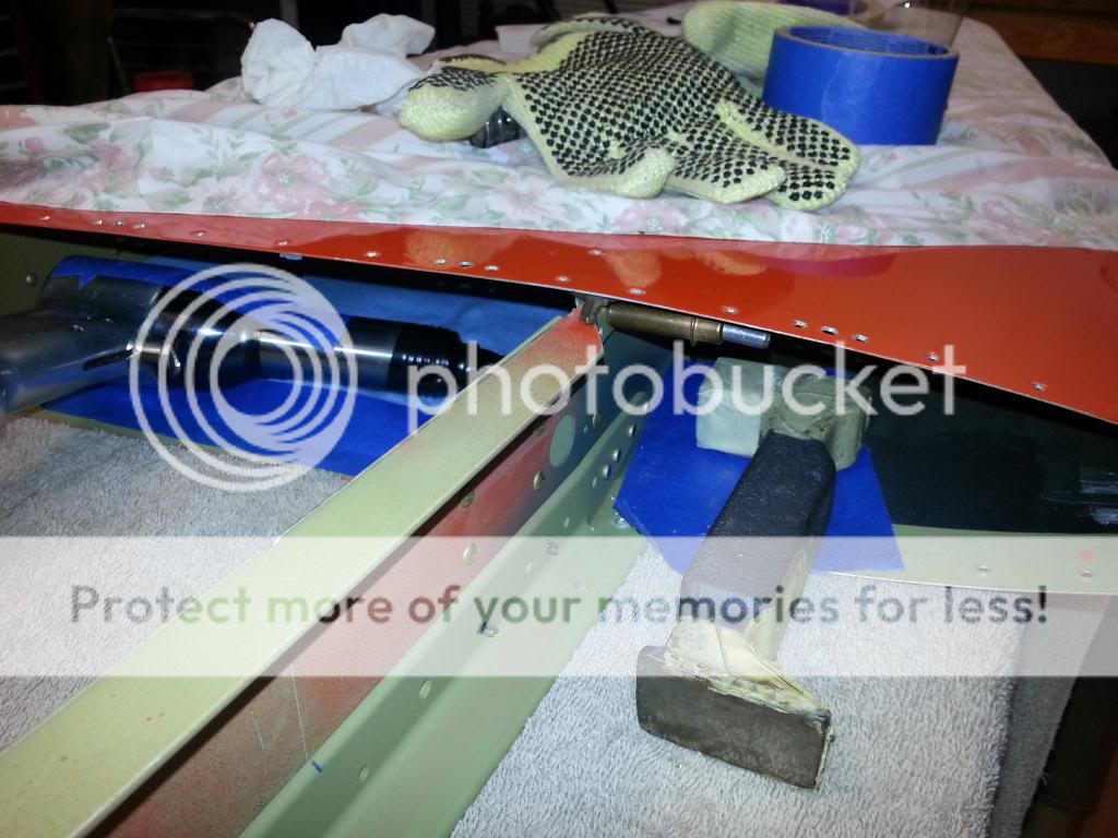
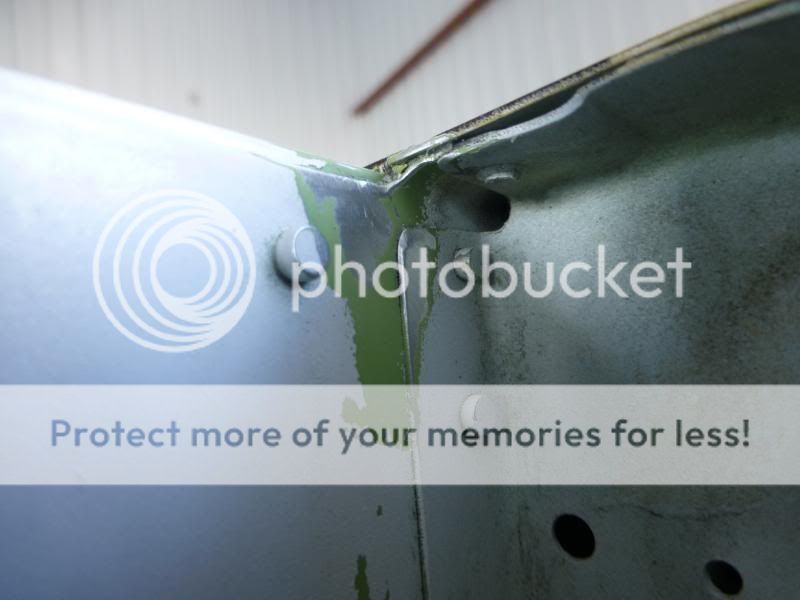
Just inspected two Aircraft today.....rv6a,685 hours ttaf,io360 200 hp ,hartzell c/s prop. Kit completed in 2001, does have relief radius.....no cracks....airplane #2... Rv8..100 hours ttaf,o320 160 hp, sensenich f/p prop....kit completed 2002..has relief radius...no cracks. Also inspected elevator spars for cracks in hinge areas.....none found on either aircraft.....mild aerobatics of less than 3.5 g on both ships
 
HOW TO FIX ???

Okay everyone, we got the message on the crack-relief-flying off carriers etc.
Now what is really needed is more info on how to do the fix. Bret, Mark, 2000, have all been very helpful. But please ---more photos with explanations.
Bret, did you drill out/off the skin at the rear spar?? Mark, how did you buck the fish mouth area rivets?? Difficult? easy?? How much time? Right hand-left hand-blind rivets???

If you plan on selling your airplane, how will you answer the "Stab Spar Mod" question. (no mod? subtract $2000).

Thanks

Ed (waiting on parts)
 
Last edited:
Another area that should be checked while doing the SB is to look at the rudder for the same cracks that might appear on the elevator. The rudder is also supported as the elevator is and loose jam nuts could cause cracks at the rivets that fasten the nut plates.
 
Finally made it through the snow to the hanger. Inspection made with paint in place, no indication of anything to worry about. Will strip paint when temps warm up enough and inspect more closely. Don't believe pushing on tail to move would cause a stress crack that requires high cycles (not nearly enough cycles).

RV-6
O-360, 180HP
Wood Sterba
First flew 2009
550 Hrs TT
Minimal acro
50% grass
ALWAYS push plane into hanger with horizontal Stab
No cracks, minimum notch
 
OK

Okay everyone, we got the message on the crack-relief-flying off carriers etc.
Now what is really needed is more info on how to do the fix. Bret, Mark, 2000, have all been very helpful. But please ---more photos with explanations.
Bret, did you drill out/off the skin at the rear spar?? Mark, how did you buck the fish mouth area rivets?? Difficult? easy?? How much time? Right hand-left hand-blind rivets???

If you plan on selling your airplane, how will you answer the "Stab Spar Mod" question. (no mod? subtract $2000).

Thanks

Ed (waiting on parts)


Ed,
I think we've all been too busy installing the kit!

The hardest part is drilling/punching out those rivets on the ends of the angles.
I used an angle drill.

The riveting turned out to be a "non-issue" for me.
Up in the tight spots I used a 3X gun with a short (3") offset rivet set.
Take the spring off the gun, there's no room for it.
Turn the rivet set for each rivet to line it up with the gun in an optimum position to hold well. Tape the rivet set to the gun with electrical tape to keep it from rotating while riveting.

Nearly every rivet requires a repositioning of the set and tape it again.
I ran the air pressure on 60 but I'm sure some 3X guns are different.

It is quite a project. More than the few evenings I had estimated. I just reinstalled the empennage back on my 7A tonight.
I plan to fly tomorrow, it's been a long time!

As to how will I answer the "Stab Spar Mod" question. I will simply tell the truth. That I had two cracks and complied with the SB by installing the Vans kit.

Good luck with yours. Just take it slow and easy on the ones that are hard to get to.

Mark


20140215_183112.jpg
 
Last edited:
Crack mod

Looks like Mark has the best idea by removing the root ribs for access. This would give more access to drill and shoot the rivets thru the spar web. Not to mention minimizing damage should the rivet set jump off and trash the spar web. I'd plan for a week of down time to do the mod based on 34 years of sheet metal experience.
 
No cracks

RV-7
O-360, 180HP
Catto 3 blade
First flew Oct 2008
300 Hrs TT
Occasional acro
50% grass
Push plane with horizontal Stab
No cracks, notched
 
Looks like Mark has the best idea by removing the root ribs for access. This would give more access to drill and shoot the rivets thru the spar web. Not to mention minimizing damage should the rivet set jump off and trash the spar web. I'd plan for a week of down time to do the mod based on 34 years of sheet metal experience.

Hi Jim,
Removing the ribs is not "my idea".
It's called out in the Service Bulletin.
And it would be impossible to do without removing the ribs.

Just didn't want to take credit for the idea.
Good luck with yours.

Mark
 
Cracks

Looks like the best option ....I've heard there's possibly a new rib in the works to allow for the doubler thickness without cutting the leg off? Sure would make it a cleaner mod. Any interest for non- builders on having this mod done for you?
 
No cracks

RV6A
0-320/Sensenich F/P
Finished 2001
260 hours
No aerobatics (yet)
No unpaved runways (yet)
No relief notches
No cracks on HS or elevator
No action until next condition inspection
 
RV-7
IO-360/Whirlwind C/S 200RV
Finished 2010
180 hours
Light aerobatics (3.5G's max)
No unpaved runways
Relief notches
No cracks on HS or elevator
 
Looks like the best option ....I've heard there's possibly a new rib in the works to allow for the doubler thickness without cutting the leg off? Sure would make it a cleaner mod. Any interest for non- builders on having this mod done for you?

I have ordered a half dozen kits (which I am still waiting on) and am currently tooling up for the repair work. I don't like being the first in line for something like this, gives me a chance sit back and learn from everyone elses mistakes :D
 
Tally through post 562

26 failures in 241 aircraft so far.
Call it 10 % failure rate. (a meaningless number with only 241 aircraft reporting)
I suppose this post is therefore meaningless too.. :D

RV6 - 8/86. 9%
RV7 - 11/72 15%
RV8 - 7/69 10%
Unspecified - 0/14

Others can summarize failure details for some patterns. I don't see one. But then, I've always been a big picture guy...
 
Looks like the best option ....I've heard there's possibly a new rib in the works to allow for the doubler thickness without cutting the leg off? Sure would make it a cleaner mod. Any interest for non- builders on having this mod done for you?

Considering that the new rib is not dimpled but the skin is, it would be hard to get them joined well to match drill them.
 
No Cracks

RV-7A
IO-360/Hartzell Blended Airfoil C/S
Finished Nov 2011
190 hours
Occassional Light aerobatics (3.0G's max)
No unpaved runways
Relief notches
No cracks on HS or elevator
 
26 failures in 241 aircraft so far.
Call it 10 % failure rate. (a meaningless number with only 241 aircraft reporting)
I suppose this post is therefore meaningless too.. :D

RV6 - 8/86. 9%
RV7 - 11/72 15%
RV8 - 7/69 10%
Unspecified - 0/14

Others can summarize failure details for some patterns. I don't see one. But then, I've always been a big picture guy...

Sadly, there will be a lot of aircraft out there that not only don't visit VAF, they don't even look for SB's. There are still rudder failures reported from time to time as an example.
 
FIX PAGE W/ PHOTOS

Everyone.....if you are on this page, you are in the wrong place! Go to "SB 01-31-14 Completed" by RV8iator, #8 (search??)

It has a dozen pictures of the Van's mod. EXCELLENT information. Add the notes by Mark (riveting the 'inside' rivets), and the note about punching out the rivets with a 'nut on a bucking bar', and life will once again become good!

Ed
 
Last edited:
This is bugging me, what is flexing to cause the crack in the first place? HS 710 and HS 714 are made out of 6061 and the spar is 2024 right? is'nt 6061 more brittle than 2024? you would think if they were riveted together, and they are, that the angles would crack first? then what if the crack then moves out to the end of the angles with the mod installed, will we need a bore scope to inspect.....ok , my brain hurts, I better get back to work.
 
This is bugging me, what is flexing to cause the crack in the first place?

No flexing is required for cracks to form. Flexing contributes to fatigue cracks. Per discussion in this thread, the failure is a strength issue, not fatigue. The sheer load carried in the webs encounters a place where the load may not flow well around the corner. This causes local stresses to surpass the limit load for the web and the material cracks.
 
Not trying to start an argument, just trying to learn from others. I can not comprehend how a crack can form without any movement. But here is a quote from another thread from someone who knows these aircraft;

(As I mentioned in another thread, the implementation of the S.B. wasn't because the horizontal stab was found to have a weak point (it was static tested and handles the limit and ultimate loads just fine), it was because with time in service it has ben found to have a slightly more flexible point that in some cases was inducing a fatigue crack. Structural strength and structural longevity are two totally different design aspects.)
 
Air Tractor had a wing fail about 15 years ago, despite testing to destruction at the factory, killing the pilot (in Arizona).

They had a spar splice fix designed, but the lower steel spar caps have an 8,000 hour life. Cycles often tell the story and I believe that is what we have here....that, and the fact that some pilots are easier on their airplanes than others.

Best,
 
This is bugging me, what is flexing to cause the crack in the first place? HS 710 and HS 714 are made out of 6061 and the spar is 2024 right? is'nt 6061 more brittle than 2024? you would think if they were riveted together, and they are, that the angles would crack first? then what if the crack then moves out to the end of the angles with the mod installed, will we need a bore scope to inspect.....ok , my brain hurts, I better get back to work.

If anyone thinks that aircraft structures are rigid, than that is a misconception, these things bend/twist/flex constantly, and probably much more than you may think.
 
Not trying to start an argument, just trying to learn from others. I can not comprehend how a crack can form without any movement. But here is a quote from another thread from someone who knows these aircraft;

(As I mentioned in another thread, the implementation of the S.B. wasn't because the horizontal stab was found to have a weak point (it was static tested and handles the limit and ultimate loads just fine), it was because with time in service it has ben found to have a slightly more flexible point that in some cases was inducing a fatigue crack. Structural strength and structural longevity are two totally different design aspects.)

Missed that post and will go back and find it. I agree with Walt in previous post, everything stains some under load.
 
I agree.

Guys you may be looking for post #277. I agree, and think it is very fair and up-front on this question. Thanks. Yours as always R.E.A. III #80888
 
Missed that post and will go back and find it. I agree with Walt in previous post, everything stains some under load.

The quote is not from this thread, it was one a while back in the general disc, (question if you ARE still building)
 
Weeee! I have not done any rivet stuff for a while. Does this mean I might be a repeat builder in the future....hope not, can't aford this one. Just Kepp drilling drilling....swimming!

DSC04461_zps57f47025.jpg
 
Looks good.
On other notes, I never understood the reason for trimming the spar flange which will leave on rivet on the skin that will not be riveted to the spar any more. Any thoughts on that?
 
Looks good.
On other notes, I never understood the reason for trimming the spar flange which will leave on rivet on the skin that will not be riveted to the spar any more. Any thoughts on that?

I think it is so you can lift the skin to get a piece of SS between the skin and spar for trimming the corners off with a cut off wheel.
 
Looks good.
On other notes, I never understood the reason for trimming the spar flange which will leave on rivet on the skin that will not be riveted to the spar any more. Any thoughts on that?

Helps to relieve the stress concentration in the corner of the web where the cracking is occuring.
 
SB 14-01-31

HS Spar inspection showed no cracks, took some time to remove the Paint overspray and Primer, but none seen. Relief notches per drawings.
RV-7, 200 hrs, some Acro, O-360, no cracks
 
RV6-A: No Cracks

RV6-A
First Flight 1996
980 Hours TT
No cracks in HS or Elevator Spars
Relief per plans
Heavy Acrobatics first 25 hours / very little thereafter
98% paved / 2% grass or dirt / 10% very poor landings :(
 
Helps to relieve the stress concentration in the corner of the web where the cracking is occuring.

Maybe, but in this case I can't understand how that would matter at all. The main problem is clearly an original design choice where the flange (on a structural beam) changes from being on the fwd side to the aft side with no overlap. Thus leaving a small section of the structural beam void of flange material which causes the shear web to carry too much compression/tension load. In fact, so much that it ends up cracking.

Since the main problem has not been addressed by the SB, the forces carried by the shear web is exactly the same amount as it was before. However, the added web material will of course make the stresses in the web much less than they were.

Fatigue in metals is a function of the main stress value and the stress amplitudes together with the number of cycles. Stress "peeks" as function of design means nothing as long as the critical values are controlled. In the SB, the single only thing that decreases stress is the added material on the web. Trimming of the flanges certainly help smoothing out the stresses, but has little or no effect on the max stress amplitudes. You cannot fool the basic laws how structural beams work.
 
Inspection report

RV8
IO360
Hartzell CS prop
1650 hours
Lots of acrobatics up to 5 G
Some unpaved runways
No relief notches
Tiny (1/8") cracks on top right and bottom left (blended out by creating notches).

Installing modification per SB

Questions for Walt:
1. one rivet hole measures .147" on the bottom angle (HS 714) and I slightly damaged (oval) one hole in the upper angle (HS 714). Should these holes be drilled out to 5/32" and AN470AD5-7 rivets installed?

2. The two rivets just inside the bend line (labeled "staggered rivet is oriented up" and its counterpart) seem very close to the notch adding to the stress riser. Would it be appropriate to move this rivet down 3/8"?
 
Last edited:
Installing modification per SB

Questions for Walt:
1. one rivet hole measures .147" on the bottom angle (HS 714) and I slightly damaged (oval) one hole in the upper angle (HS 714). Should these holes be drilled out to 5/32" and AN470AD5-7 rivets installed?

2. The two rivets just inside the bend line (labeled "staggered rivets is oriented up" and its counterpart) seem very close to the notch adding to the stress riser. Would it be appropriate to move this rivet down 3/8"?

I appreciate your confidence in me, but, I know my limitations... when it comes to deviating from an approved spar repair I think the engineer would be the best place to go for that info.

It's "probably" ok as most engineers will build in some buffer for mistakes, but I don't think probably is good enough in this case, get the answer from "the man".
 
Last edited:
Since the main problem has not been addressed by the SB, the forces carried by the shear web is exactly the same amount as it was before. However, the added web material will of course make the stresses in the web much less than they were.
???
Not sure how forces/stresses can be the same and be less at the same time...

Fatigue in metals is a function of the main stress value and the stress amplitudes together with the number of cycles. Stress "peeks" as function of design means nothing as long as the critical values are controlled. In the SB, the single only thing that decreases stress is the added material on the web. Trimming of the flanges certainly help smoothing out the stresses, but has little or no effect on the max stress amplitudes. You cannot fool the basic laws how structural beams work.

As mentioned previously in the thread, this mod is not for making the structure stronger. Previous static testing has already proven that it meets the design requirements for limit and ultimate loads.
The SB is to a localized stress area that after lots of load cycles can possibly develop a crack. Tapering the flange of the fwd. spar, and confirming that there is a tapper in the top flange of the top angle does help further distribute the load through this area. This was substantiated with FEA and is also a fundamental engineering practice.

Please refrain from comments that might make people take shortcuts while doing the SB modification, without having personally done a full analysis of the structure.
 
Not sure how forces/stresses can be the same and be less at the same time...
Stress = Force/Area

The forces are the same. Your airplane weighs the same, you pull the same amount of G etc. Adding more material obviously decreases the stress in the material. ABC in engineering.

Tapering the flanges weakens the structure further. It does however, smooth out the stress distribution. But to what gain? Absolutely none stress wise. The stress at the weakest point does not change if you weaken the area around it. The strains could benefit from the tapering however, making the HS flex in somewhat the same way as before. This could in fact be important regarding vibration and also for the other SB, the cracks in the elevator.

Static loads and fatigue loads are different things. But stress and strain does not differentiate between the name of the load. To decrease stress, you increase material dimensions for a given load (force). This is the same for static loads and dynamic loads.
 
I strongly recommend that people installing the doubler parts prescribed in the SB do not take short cuts and skip any of the steps.
 
Stress = Force/Area

The forces are the same. Your airplane weighs the same, you pull the same amount of G etc. Adding more material obviously decreases the stress in the material. ABC in engineering.

Tapering the flanges weakens the structure further. It does however, smooth out the stress distribution. But to what gain? Absolutely none stress wise. The stress at the weakest point does not change if you weaken the area around it. The strains could benefit from the tapering however, making the HS flex in somewhat the same way as before. This could in fact be important regarding vibration and also for the other SB, the cracks in the elevator.

Static loads and fatigue loads are different things. But stress and strain does not differentiate between the name of the load. To decrease stress, you increase material dimensions for a given load (force). This is the same for static loads and dynamic loads.

The stress is more than just the force/area as you know from solid mechanics. A notch will lower the area, but the strain is not evenly distributed, and that means resulting stresses are not evenly distributed. The well known concept of stress concentration is at play. Further, this is not a simple structure of load distribution due to stiffness differences between the components and added stiffness by the skin that build up to carry the loads imposed on the spar and load sharing.

Personally, I will completely trust the stress analysis and follow Vans instructions in the SB. IMO, any discussion of how this works, in detail, is well beyond the scope of this forum to definitively address.

Just my $.02
 
....Static loads and fatigue loads are different things....

And they behave quite differently for ductile materials like the ones used here. For strength, the whole piece will be effective. Most localized stresses or strains will locally yield and distribute their excess load to the adjacent material. But for fatigue and crack propagation, the cyclic stress is generally below the yield level and the material around local load concentrations has not had the benefit of that distribution. It is affected by whatever load concentrations are caused by the geometry.

From what Scott has said, Van's has used finite element analysis to assess this. That analysis tool, when used for a linear static analysis with a properly modeled structure, is excellent for finding these load concentrations. It appears that is what led to this SB. Since he's said that this analysis also verified that the SB fix is indeed a fix, the SB would be perfectly adequate to correct the cracking issue here.

Since the cracking is a fatigue issue and not a static strength issue if there are no cracks, it's unlikely that the fatigue damage, which accumulates, can made to go away without it since the geometry of the structure has not been changed.

Bottom line - do the SB.

Dave
 
Something everybody should keep in mind...If you do not use the materials and don't follow the procedures as outlined in the service bulletin and deviate, then you have not complied with the SB. Just something that the FAA,insurance companies,and lawyers will take note of if they should be involved at some point in the future.
 
I have a question about step 13 of this SB on page 8 of 20. (Ref Fig. 5). I couldn't find this addressed anywhere else prior to posting this so if I somehow missed it; my apologies.

Step 13 calls out a final drill of the fwd most hole in the top and bottom flange of the main ribs. No problem, I bought some #27 bits. However, on page 19 of 20 in Figure 11, the rivet callout for this location is still AN426AD3-3. If this is the case, why increase the size of the hole from the original callout? What am I missing?

I am not quite to that point but I think the rivet is a hole filler, they do not want the flange attached to the skin so the #27 hole is so the hole in the skin can be filled with the -3 rivet. It's bucked end sits in the #27 hole.
 
I have a question about step 13 of this SB on page 8 of 20. (Ref Fig. 5). I couldn't find this addressed anywhere else prior to posting this so if I somehow missed it; my apologies.

Step 13 calls out a final drill of the fwd most hole in the top and bottom flange of the main ribs. No problem, I bought some #27 bits. However, on page 19 of 20 in Figure 11, the rivet callout for this location is still AN426AD3-3. If this is the case, why increase the size of the hole from the original callout? What am I missing?

I believe it is to increase the size so the rivet can expand more to fill the larger hole since there is no mating piece to this hole. I could be wrong though.
 
I have to wonder how the FEA copes with the poor sizing of the flanges with the older RV-6 kits, and shown in Turbo's pic -

P1010559.jpg


Also most of the early models have poor "height control" of the parts fitting here (main rib, spar bent flange, the riveted on forward angles) and the skin is rarely smooth as it crosses over the HS spar.

Required edge distances are also missed in this area. Check the earlier pictures in this thread.
 
I am not quite to that point but I think the rivet is a hole filler, they do not want the flange attached to the skin so the #27 hole is so the hole in the skin can be filled with the -3 rivet. It's bucked end sits in the #27 hole.

Thanks for the reply David. You make a good point. I will drill on...
 
Did the inspection last weekend but had not removed the paint to be absolutely sure no cracks. Today Used Dan Horton's post (#548 in this thread) to use MEK on a cotton ball taped down with aluminum tape to soften polyurethane. Worked Great. Now sure no cracks.

RV6A
620 hours
180hp IO-360
Fixed metal prop
Quick built Kit 60171 circa 1999 (therefore built in the Philippians)
Never grass
Minimal acro
Small notches
No cracks
 
Last edited:
Back
Top