What's new
Van's Air Force

Don't miss anything! Register now for full access to the definitive RV support community.

Help Vertical Power Develop New Product

Status
Not open for further replies.

MCA

Well Known Member
Advertiser
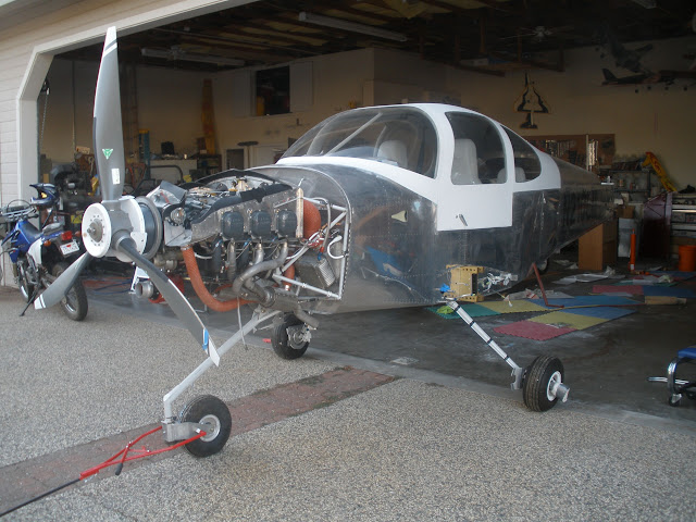
We?ve been working on a new product recently, and thought it would be fun and useful to share the development process here on the web. We?re all invested in building an aircraft ? so we hope you?ll find it interesting to see what goes into building a product that goes into the airplane.

When building a new product there is a lot of initial up front work and planning. Here are some of the questions that need to be answered early on:
1. What problem does it solve?
2. Does it fit with our expertise and product strategy?
3. What are the existing and future competing solutions?
4. Can we build it at a price that we think the market will bear?
5. Do we have the resources to do it successfully?
6. What will it cost to develop, and how soon do we expect to make our money back?
7. Are our resources best used on this product or another product?

For the homebuilt aircraft market, we?re a big believer that making things simpler for builders (and not affecting the 51% rule) is a good thing. For example, Van?s Aircraft pre-punches their skins and even offers quick-build kits. Building an RV-14 is a lot easier than building an RV-4, but it is still a project.

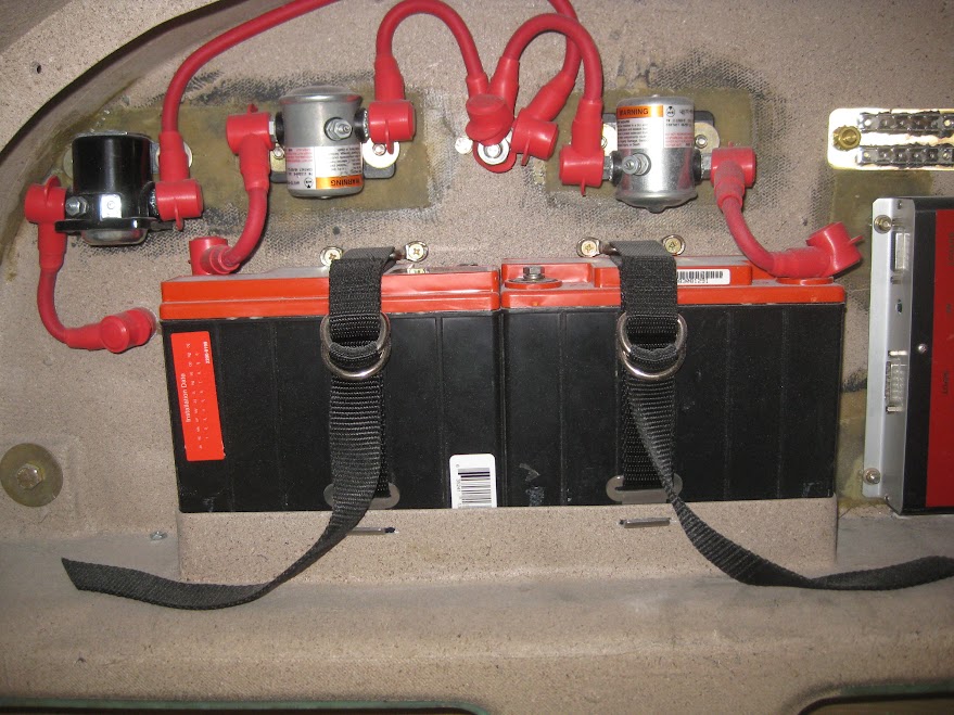
We believe the VP-X makes wiring the aircraft easier. It is focused on what is called the secondary power distribution system ? the smaller circuits that power the aircraft systems. For us, the next logical product extension is the primary power distribution system ? managing main power (big wires) throughout the aircraft.

PrimaryBus.png
 
After a lot of internal meetings and talking with people outside the company, we determined that simplifying the primary power distribution system had a lot of value to builders. So what is that exactly?

Most modern experimental aircraft have a single bus electrical architecture – meaning one large battery, one battery contactor, and one or two alternators. Builders may also install a backup bus with a small battery for the EFIS. So, just like the VP-X, the proposed product is designed for the electrical configuration that most builders are using today.

So… you might ask, how do you simplify a couple of relays? When you look at the primary power system installation in more detail, there’s actually more to it than that. There’s a bunch of stuff that looks something like this:

old_rig1.jpg


Note about this picture: An ANL fuse is shown between the battery contactor and the main bus wire. This is not normally installed (but can be). The PPS is intended to provide this functionality and therefore this fuse is included in the mockup.
 
Last edited:
The proposed solution to replace the old stuff currently looks like this:

PPS_front1.png


PPS_back1.png


It is roughly 5 inches square and 1.6 inches deep.

The placard below (which we?ll have at AirVenture) shows how this is wired into the aircraft.

PPS_Placard.png


Note: only one alternator is shown, but it will support two alternators.

The proposed primary power system (PPS) can replace the following items:
? Battery contactor
? Starter contactor
? Bus bars
? Ground blocks
? Firewall safety pass through
? Diodes, fuses, fuse holders

The cost of these components ranges from $207 to $375, depending on the source and quality.
 
Some key design elements:
? All solid-state.
? Innovative rear connector pass-through design eliminates need for separate firewall pass through.
? Enclosure reduces exposure of hot (+ voltage) wires.
? Longer threaded lugs than a contactor so you have more room to attach multiple cables.
? Stainless steel to resist engine fires.
? High-temp internal components to operate in the engine compartment.
? Sloped enclosure roof and other features to resist water.

As it is spec?d now, it will work with both the VP-X and conventional breakers. It?ll work with a mag/starter key switch or a regular start button. Here are some initial dimensions (PDF file).

To install it (let?s say a typical RV), you drill four holes in the firewall for the #10 (AN3) mounting screws, plus two larger holes for the connectors. The positive battery cable connects to the terminal on the top left. The starter cable connects to the terminal on the top left. The alternator b-lead(s) connects to the alternator terminal on the bottom left.

Inside the cabin, you can run a 6 or 8 AWG wire from the main bus connector to the VP-X or your circuit breaker panel. The master switch and starter switch wire to the 9-pin connector. There are also pin-outs for a fault lamp and fault reset button (you can use a single lighted button to combine these into one item).

That?s what we have for now. We?d like to get your feedback and comments both here on the forum and at our booth at AirVenture. We will filter all feedback and see if it meets our criteria above. Thanks for taking a look!
 
How would this work with rear mounted batteries? Wouldn't they have a long main power line that would be continuously hot?
 
Nice idea. Although it looks like the firewall pass through won't work with aft mounted batteries (-10).
 
Cool. Very, very cool. Now, if I were to have a wishlist, it would be the following: 1) ground power circuitry. 2) Remote starter module (thinking RV-10 with battery in the back). 3) Additional main power circuit. I'm not sure if the VP-X already handles this but my A/C is separate from the VP-200 system due to the power load (though it could certainly handle the solenoids for the AC).

Also, will it handle dual batteries and/or alternators? In the diagram it looks like you have two alternators feeding into a single input but how would that work?

Please don't think I'm nitpicking; I'd have loved to have one of this when I built the RV-6A, and there are more simple systems than there are complex ones like the one in my -10. I think this is a brilliant idea; I'm just greedy. :D More, more, more ...
 
I agree with the others. I like this idea, but can it be made to work in a -10?

Edit: In the time it took me to write this, others above stated my same question!
 
Yes, it can work with a rear mounted battery.

In that case you do have to leave the master solenoid in the back per Van's plans. The master switch would be wired to both the solenoid in the back and the PPS in the front. The PPS would be mounted on the firewall where the starter solenoid is on the -10 today.

At least I think so, we haven't tried it yet. Can anyone with a -10 see how this might fit there?

We'll have some detailed wiring diagrams to post in the next few days.
 
Via email:

Thanks. What you see is mostly what we have so far. I can't commit to a timeframe at this point - we're hoping by end of the year-ish.

Marc

On Jul 16, 2013, at 3:03 PM, wrote:

Hey Marc,

This look frickin fantastic. I hate wiring all that stuff!!! How far out are you on this? I was going to mounting the old school gear when I get home from Oshkosh. Perfect timing.

Please let me know!!!!! I could be one of the first on the block:)
 
I'm a huge fan of my VPx. I think it's pure magic.

On the new product my questions would be, how does this new box work with rear batteries (RV8) and how does it replace the ground block?
 
very nice, marc!

the inherent firewall passthrough is a brilliant idea, agree somewhat though that it may only work with certain setups/aircraft.
how about making two versions with the stud either fore or aft?
if a single version is a must, i'd rather go for the stud firewall forward

also, an ammeter / charging / decharging sensor inherent would be great!

other than that, design, approach, everything looks vertical power quality :)
 
Yes, it can work with a rear mounted battery.

In that case you do have to leave the master solenoid in the back per Van's plans. The master switch would be wired to both the solenoid in the back and the PPS in the front. The PPS would be mounted on the firewall where the starter solenoid is on the -10 today.

At least I think so, we haven't tried it yet. Can anyone with a -10 see how this might fit there?

It wouldn't quite fit there (there's some other stuff, like the sender headers on the hot side and the brake line bracket on the cold side) but it could be located nearby. More to the point, for a -10 I'd also want the battery lug on the back side so I don't have to make another exposed firewall penetration. Or, remote the starter instead of the master; there's plenty of room in the tail for your box.
 
Cool. Very, very cool. Now, if I were to have a wishlist, it would be the following: 1) ground power circuitry. 2) Remote starter module (thinking RV-10 with battery in the back). 3) Additional main power circuit. I'm not sure if the VP-X already handles this but my A/C is separate from the VP-200 system due to the power load (though it could certainly handle the solenoids for the AC).

Also, will it handle dual batteries and/or alternators? In the diagram it looks like you have two alternators feeding into a single input but how would that work?

Patrick - thanks for the feedback!

It will not handle a true dual independent bus system (See Aero Electric Z-14 diagram), but if you have a second battery used to backup avionics that can be wired in separately.

Detailed wiring diagrams coming soon!
 
Yes, it can work with a rear mounted battery.

The PPS would be mounted on the firewall where the starter solenoid is on the -10 today.

At least I think so, we haven't tried it yet. Can anyone with a -10 see how this might fit there?

The batt and the starter posts are backward to mount FWF in a 10, at least in the same location as the starter solenoid.

Starter solonoid is above the oil cooler here, batt feed wire is the one with the 180* turn.

P9250018.jpg


A rear feed for the batt would work well for any setup with the batt in the back.

What about those of us running dual alt/dual batt in a parallel setup?? I could see two of your boxes working with only the addition of a cross feed to the essential buss------or a single box with dual inputs for batt and alt.
 
Last edited:
Well done!

Hello Marc

Well done! I would buy it on the spot.

Same comments as Bernie.

But, make two versions, so that it fit for each style nice and is not a combined solution.

Regards,
 
I'm a huge fan of my VPx. I think it's pure magic.

On the new product my questions would be, how does this new box work with rear batteries (RV8) and how does it replace the ground block?

Rear battery - wiring diagrams coming, but it will work.

We're currently proposing that the system comes with a 'farm of tabs' for the ground block. The hole spacing matches the mounting holes on the back of the PPS so you can mount it on the inside of the firewall, or you can mount it anywhere you like really.

GNDBLK.png


The large hole is so you can also mount it to the big ground cable coming from the battery. We're planning to offer the ground block separately as well if you need more than one.

Thoughts?
 
If I were building again ....

I would definitely consider this option. This certainly would have made wiring FWF easier the first time - when I had to figure out how to do it and what components to use (I did not use Van's components).

A couple of questions:
1. I use a 3 position switch for the Master/Alternator field: Off/ Master only/ Master + Alternator. Can this device turn on the Master without turning on the Alternator also?

2. I have an Emergency E-Buss Switch which applies power to the E-Buss with the Master Off (i.e. Master Contactor Off). I presume if I wanted have the same capability the PPS, I would do it the same way I do today (direct to the battery). Right?

3. I use toggle switches for my ignition and a separate push botton for the starter. Would the pin outs of the "starter switch" on the PPS support this configuration?

Good luck with this product. I looks great.

1. & 3.
Rick, the pinouts are designed to exactly mimic the way you wire these things today. So any switch configuration you have today or are planning to use will work with this.

2. Yes, go right to the battery lug. The longer lugs here are exactly for that purpose.
 
What about those of us running dual alt/dual batt in a parallel setup?? I could see two of your boxes working with only the addition of a cross feed to the essential buss------or a single box with dual inputs for batt and alt.

Mike, Both alternator b-leads are wired to the alternator post.

Dual batteries in parallel are fine - they are wired together then a single cable into the battery input terminal. Batteries in parallel are treated like one big battery.

The essential bus wires right to the battery terminal, just like with old relays.

The system is designed to 'fit in' to the way things are wired conventionally, so 99% of builders should be able to tap into the proper place for an e-bus, backup alternator, backup battery, etc.
 
Last edited:
Will it support ammeter outputs for the EFIS for each battery and alternator?

I could put this in today. I'm right there.

That's something we're looking into. Would be great to get rid of the external shunt as well. The internal circuitry on the alternator control does measure current, but we need to convert it to a format that mimics a shunt.
 
I like solid state, mechanical solenoids require maintenance and will quit working at the most inopor tune time. Having everything in one nice ss box is also very good. My rv8 battery is in the fwd baggage, so the thing for me is to have the battery lead on the same side of box as the other connections coming from the interior of aircraft. That would facilitate the one firewall penetration that concerns me.

Bird
 
Great Idea

I was already considering to go solid state for my master relay and to get rid of the starter solenoid by using the starter's built-in as SkyTec recommends here (see Rewire the NL starter link).
Being late in the build has some positive aspects like this one :) when the perfect product appears on the market BEFORE you have reached the building stage where you need it.:D
Congrats and count me in as a future buyer.
Cheers
 
Were I still building, I might be interested in the product. What concerns me is how quickly VP turns over its product line.

But, yeah, it definitely has some electrical sex appeal.
 
Mike, Both alternator b-leads are wired to the alternator post.

Dual batteries in parallel are fine - they are wired together then a single cable into the battery input terminal.

My system is a bit different than that------each alternator charges a battery through the normal regulator and switch setup. Both systems are independent of each other, what I describe as parallel systems, only cross connection is a Schotkky diode allowing the main to feed into the E buss. The aux system feeds the E buss directly. If the aux system goes south, the E buss gets its power seamlessly through the cross tie/Schotkky diode.

At engine start I already have the EFIS powered up on the aux circuit, so I get engine readings instantly, and no brown out due to starter draw.
 
What concerns me is how quickly VP turns over its product line.

i agreed on that when the vp200 was discontinued without proper feature replacement.

but in this case, the product is fully complementary (even to the awesome vp200) as well as the newer vp products.

as a reference point, there is a similar (but old fashioned, non-solid-state) product that does more or less the same, "Lamar MC10" at >1000$. price being probably one of the reason why it never was adopted much in the experimental scene.
one notable feature it has is a massive "standard" ground power plug.

pricing would have to be significantly lower were i building again and considering the new VP Primary Power "PPX".

has there been an official or working name for the product already?
PPX kind of would make sense and is easy to reference.


good luck,
bernie
 
I need one now! I may be able to wait to the end of the year. As a first time builder this would simplify my installation greatly. I would be willing to pay the price is listed.
 
I can wait a couple months and will have to move on if its not ready but sure would like to get on the first run list otherwise.

Wish list:
Security, ideally a proximity key fob that locks the ppx when i walk away. Or a numeric code i can enter into the efis to allow power to the starter circuit.

Eliminate the need for the massive skyview ammeter shunt.

Comes with the required indicator/reset button with a pre labeled window.

How soon can i send you my money for one?
 
Last edited:
Great

Great.
I'm not looking forward to electrical wiring, so I'm very interested in anything that makes it simpler. I'm still at least a year away from starting the electrical system, have already decided for the VP-X (and dynon) and you can count me in to buy this new box when reaching that stage.
Keep good things coming at us ;-)
 
Oh, Yeah...

Please make it work for the 10!

I would also love to see the ability to use a prox key, like the Infinity cars. A key code lock would also work...

Rv-10, rv-10, rv-10.....

Hurry!
 
Yes, we definitely want to make it work for the -10!

From an email:
Q: I'm build an RV12 as amateur built. Will this unit work with mainly light sport aircraft using the Rotax built-in alternator?

A: We are looking at an LSA version of this with lower circuit protection values for LSA - somewhere around 30 amps vs 80 amps on the b-lead and main bus.
 
How much will it weigh, and how does that compare to what it's replacing?

Thanks,
Dave

Dave,

At this stage we don't have any hard numbers, but here's what we know now:

weight of contactor rig (shown on first page of this thread): 3 lbs

estimated weight of PPS: 2 lbs
 
Last edited:
Not sure...

We're installing the VP-X pro, and I have to say, I like that product a lot.

This one, though, wouldn't help us much. By the layout of the connections and the feedthrough it has made a lot of assumptions about which side of the firewall certain things are on. In our case (A Cozy Mk-IV) those assumptions are wrong. We have our batteries and contactors on the cold side of the firewall, and there are feedthroughs for alternator and starter.

Add to that that the flexibility of the separate contactors and whatnot allows us to have twin batteries, and we can feed the main bus from either one.

Don't get me wrong, I think there is an opportunity here, but maybe the details don't work for all installations. The cold side of our firewall is a mess of #4 cables to accommodate three contactors, two batteries, one forest of tabs, three feed-throughs (alternator, starter, and the ground lug). This could be cleaned up a lot with this new product, but the feed-throughs would be all wrong for us.

IMG_2166.JPG
 
Last edited:
Mounting point

Make the four mounting points go through the unit with steel sleeve for drilling.
That way you only have to find the two drill points for the cable pass through.

William Bennett
RV8A for sale
RV7 finishing
 
The system is all our own design - we are not using third-party relays.

We now have a draft INSTALLATION MANUAL with wiring diagrams on our web site here. (scroll down to the PPS section)
 
Last edited:
Need one:)

I think this is one of the coolest things to come along in a while. We're talking minutes instead of hours to install.

Get this thing happening!!! I'll do everything I can on the new plane to hold off until this is out.

Can't wait to see it at Oshkosh.
 
I think is important that the product include a weather resistant box and the possibility to conect a ground power outlet.

Regards
 
With respect, may I play devil's advocate?

The "easy wiring" appears to eliminate only four connections, the stud-to-stud strap bolt-ups between the contactors and the ANLs. The remaining wire count is the same. The product still needs physical mounting, and still needs a hole cut in the firewall. Good firewall penetrations do not require the kit in the photo.

Solid state relays are indeed a plus. A builder can choose to install them independently.

As presented, incorporating a single rear battery returns the total component and connection count to the same as conventional wiring.

A rear battery setup plus a rewired NL starter eliminates all functions provided by this product, and weighs less.

The builder will be required to install the control wires into a plug rather than simple crimped ring terminals. Counting OEM installed connections, the total connection count is increased. Example; ring terminal at start switch->wire->crimp in plug->pin to socket->crimp in plug->internal connection to SSR. The usual method is a wire and two ring terminals, meaning two ordinary AMP terminal crimps.

The plug itself will be somewhere on the cabin side of the firewall, alongside the main bus connector. That means doing an upside down dive under the panel to service or connect/disconnect either one.

Is anything repairable in the field as an individual component, or does service require removing all connections and the box itself?

Builders who may be uncomfortable with wiring often order a Vans harness. Incorporating the product will require that they vary from the prescribed installation, which defeats the point of using the Vans harness. Builders with elaborate architecture won't mind the four extra bolted connections, and won't need to devise workarounds or request special configurations.

Devil's advocate mode off.

Suggestion: simply market individual SSR/SSB components which are swap-in replacements for old fashioned mechanical components, right down to the mounting bolt pattern. They could be sold to non-VP customers with older experimentals as replacement and upgrade parts (what, 7000 RV's alone?), STC'ed for production airplanes, and configured by EAB users in multiple ways. The marketing angle is good; it leads a larger number of customers to VP with an initial small purchase, often before any avionics purchase.
 
I like it! A few of us local builders have discussed this before. Looks like it is finally a reality. Before I finished the install, I had stopped by others' hangars to see how they "did it." I have had a few builders stop by my hangar to see how I "did it." I would say, "wouldn't it be neat to have just one box to mount on the firewall to take care of all of this stuff." LOL I look forward to seeing how this progresses.
 
Airframe Ground?

As far as I can tell from the draft installation manual, this relies on an airframe ground or a completely separate ground system. Certainly for the starter and probably for everything else.

Is this correct?

Dave
 
Starters are naturally grounded when bolted to the case. The battery is grounded to the airframe and to the motor in two different places. Every thing else gets grounded to the "field of grounds" if not grounded by design.
 
Suggestion: simply market individual SSR/SSB components which are swap-in replacements for old fashioned mechanical components, right down to the mounting bolt pattern.

Great minds think alike! :cool: This is on my to-do list, if someone else doesn't get to it first (my to-do list is long...).
 
Please keep the feedback coming. We like to hear from both sides of the aisle. As we make progress, there are several outcomes:
- make the product substantially similar to what is presented here
- modify the product a good amount
- come out with an entirely new product
- choose not to take the product to production

We’ll see where things go.

Here’s the feature feedback so far:
  • Unit that does not have pass-through capability. All lugs mounted on same side of firewall.
  • Unit that also has the battery input on the back side (firewall pass through)
  • Ability to connect to shunt inputs on EFIS, eliminating need for external shunt.
  • Backup battery charging and tie-in circuitry.
  • Retrofit form factor, to directly replace mechanical starter and master solenoids.
  • Integrated ground power plug.
  • Remote the starter.
  • LSA version (lower breaker values).
  • Proximity key fob, key code lock, or similar.
  • Includes reset button/light with proper labeling.
  • Four mounting points go through the unit with steel sleeve for drilling.
  • Trickle charger circuit for aux battery
  • Smart master switch with auto-shut off
 
Last edited:
  • Retrofit form factor, to directly replace mechanical starter and master solenoids.

This sounds like something that you can market regardless of whether or not you proceed with the unit discussed here. The new unit may end up being great for projects still being built while the solenoid replacements would be usable by the flying fleet.
 
Status
Not open for further replies.
Back
Top