What's new
Van's Air Force

Don't miss anything! Register now for full access to the definitive RV support community.

behind the panel bracing recommendations

scrockard

Active Member
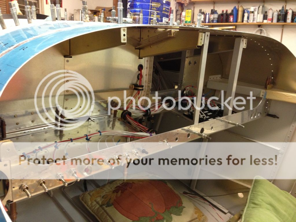
Does anyone have recommendations (and pictures) of what you did for bracing behind the panel?

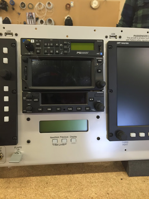
I'm at the early stages of a panel design and cantilevering a stubby glass avionics display off of the front panel with no bracing in back just seems like a bad idea? They don't weight too much but there is some weight there in the electronics box behind the display.
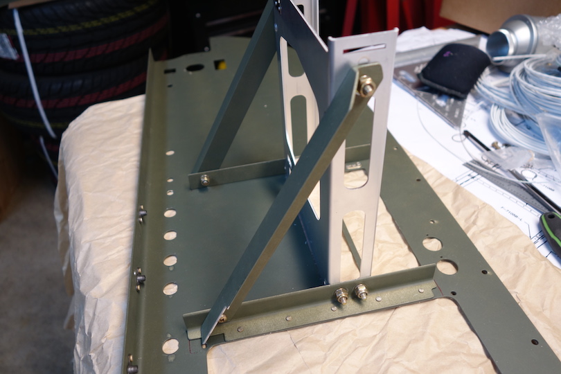
:) This is what I am going to water cutter with - added 12/23/14
N191SD_panel_rev2.jpg


original idea
rv9a_panel_incomplete.png
 
Last edited:
Is yours a tip-up or slider? I think the structure geometry is different. If it is a tipper I will find and post my pictures. I bridged the right side and made and angle for the pilot side. It was very stiff with some a little care.
 
I have an 7A slider and I put two Skyviews, not side by side, but had it to do over I would. I have no bracing behind. Not a problem, not saying one cannot or should not, I just did not. Works ok I think.
Dave
 
7 slider glass panel

I added a tray behind the PFD & MFD to hold some of the boxes for the G3X as well as brace the panel. The fuse tray braces the copilot side.
0A95B86F-293F-4C11-A667-3906488A41A7-252-00000016EE5FA271_zpsa39d5a4b.jpg


I also added some aluminum angle braces fro the ribs to the rear of the subpanel, overkill I'm sure but my control cables and panel are very solid.
 
Davoakes response:
I'll take that into consideration. I imagine a lot of people are doing / have done the mounting of a glass display with just a panel cutout as the support.

Having never done this before, I've been looking for ideas is all. With an RV-9a, I'm not allowed to rattle the wings as much as you can in the 7 so maybe I'll be good with that idea... :)
 
Last edited:
wow - That is nice and tidy wiring back there!

Those aluminum braces look like the standard spot to put the radio stack? Your picture gives me an idea that I better account for those angle spacing in my design - Thanks!!!

I see your fuse block on the right side. I assume a grounding block is somewhere back there too (maybe not pictured)?

Also - it looks like you have a full bottom from front panel to the back sub-panel. That is a great spot for mounting other items...

Thanks for sharing that picture.

Yes, I attempted to pre-build the radio stack cutout. Hopefully I'll know how well I did in another month.

Grounding forest of tabs is on the firewall recess on the inside, the outside is the ground lug for the battery.

I originally built the shelf behind the PFD & MFD for the GSU73, it was quite a bit larger and had more specific mounting requirements than the GSU25 I ended up with. Probably overkill but gives me space for new boxes.
 
wow - That is nice and tidy wiring back there!

Those aluminum braces look like the standard spot to put the radio stack? Your picture gives me an idea that I better account for those angle spacing in my design - Thanks!!!

I see your fuse block on the right side. I assume a grounding block is somewhere back there too (maybe not pictured)?

Also - it looks like you have a full bottom from front panel to the back sub-panel. That is a great spot for mounting other items...

Thanks for sharing that picture.

Be careful with your radio location. Do not mount it too low. Mine was cut about 1/2" too low and it bumps into the bottom angle of the sub panel with the antenna connection. I am having to go through gyrations to make it work. If it had been cut just a little higher, it would have saved me several hours of work. Mine is a 9A tip up.
 
Good advice on the radio. I noticed that my GTR200 is fairly long and approaches that back sub-panel wall. I'll pay more attention now to the antenna and other connector. Thanks.
 
Radio

I've been doing some preliminary work on my panel too. I plan to use 3/4" angle as shown earlier to mount the radio stack. I'm wondering if 1/16" is sufficient or if 1/8" would be a better choice? The 1/8" seems like overkill, but then the 1/16" too light weight. I'm on the fence right now.
 
Same here - I have a water cutter deadline for tomorrow so what I will be doing (right or wrong) is to use a framework of that lighter angle AA6-063-3/4x3/4.

At least at this moment, I'll plan on creating a design that is a basic box that ties back sub-panel to front panel in some creative way. It's the support on back of radios that I'm concerned with. I don't want to build a brick %^&* house here so keeping it light I hope. lol

Also - I'll update my pretty picture later today with latest layout and perhaps with my internal radio stack bracing. I really didn't find too many people sharing this information - kudos to those do do!

Thanks,
Scott
 
A good thread here. I'm at the panel stage, and I'm a little bummed that the GTR 200 and probably the transponder (GTX 327) will need a sub panel cutout for clearance in my -9A, and some sort of rear support. I thought they might be light enough to use just the front rails, but that's asking for trouble. I'll post here with my solution in a few days.

I think the .063 angle will be OK with front and rear support.
 
Last edited:
I made a cutout in the sub panel to fit the GTR200, and supported the bottom of it with a piece of angle across the bottom. No picture right now but it is simple and plenty sturdy.
 
Wiat till you have your harness

One thing I wish I did was not waste my time on was building panel supports that do now work now that I have my panel and harness. What I am doing now is finding places to put all the components and still brace the panel. What I had built did not work.
 
I noticed two things today after basically verifying the panel (prior to watercutting).

1. The Vans DXF file doesn't show the bottom flange in the panel and I had initially used up all of the panel height not realizing this problem. After printing some legal sized 1:1 copies out, I discovered my error and moved the components up and closer together in some cases. whew - glad to have caught that one!

2. I noticed that the GTR-200 is close enough to back sub-panel that I think any minimal bracing might just be a simple piece that sticks out from the back sub-panel that attaches to the side of the slide-in case that comes with the GTR-200.
Of coarse as pointed out, an access hole behind the connectors on GTR-200 is needed.

Note: I am using three GTR-200 drawings as cad place holders in the panel - I'm actually holding out for the lynx adsb transponder scheduled for Jan/Feb release next year... I hope they all fit in the planned space!
 
I made a cutout in the sub panel to fit the GTR200, and supported the bottom of it with a piece of angle across the bottom. No picture right now but it is simple and plenty sturdy.

Sounds like a good solution...thanks. :) Since the GTR200 tray extends farther forward than the transponder tray beneath, I think I'll connect the rear of the two trays with aluminum straps on the sides, and then have the GTR200 tray rest on the angle.

Is yours bolted to the angle in back, or does it just rest on it? Maybe put a piece of weatherstrip foam here to damp vibration?
 
Last edited:
I'll probably screw attach the GTR-200 tray to its rear support which attaches to the rear sub-panel.

I like your idea of tying the two or more panels together back there from the main one that is attached to the rear panel. This is the minimalist bracing that seems correct.

P.S. I found another major flaw with my panel layout. The specifications on the cut out for the GTX-330 is 1.65" (supposedly similar to the l-3 lynx adsb system) high and using just a GTR-200 as a space holder won't work. Now I have the challenge of finding approximately .4 to .5 inches of vertical room in the buffer areas top and bottom on the radio stack column.

Do you already own all of these boxes? If not there are a number of things you can do to make the stack a bit easier to work with like using a panel mount rectangular Trio autopilot, or going with a different transponder (is your 330 an ES?), moving the EIS box (you can still have it, but if you rear mount it through the panel over the right you'd have a pile of stack space, still have the EIS to read, and also all that area for a tablet or whatever you plan on over there)....in fact I might have a tendency to move a few things around if it were me.

Just some thoughts.

Cheers,
Stein
 
Hello Stein!
I came to similar conclusions at lunch time today as I was studying that huge blank panel space on the right. That space was for my own experimental avionics but that is now going to get used up! My radio stack space looks terrible with the existing layout and is just too tight for my vertical stackup.

I'm going to leave more buffer space below the radio/transponder stack just in case I need to modify for unplanned space changes in that area.

I should have gotten the rectangular version of the trio - oh well. The EIS is kind of bulky too and doesn't really fit very well on any panel...

I'm going to need an L-3 lynx ADSB in & out + WAAS gps transponder when those guys finally release the design and start selling soon - are you going to be a dealer for them? They had a regular medicine show going on at kosh this past year. I'm lined up hopefully for some of that L-3 ADSB snake oil! :)

Thanks,
Scott
 
I'll post a few more pictures of what the internal bracing looks like once I start hooking up the harnesses and mounting the panel hardware. This might take me a few more weeks...

I'll also trim down my panel pictures to a more reasonable size.
 
Hello Stein!
I should have gotten the rectangular version of the trio - oh well. The EIS is kind of bulky too and doesn't really fit very well on any panel...

I'm going to need an L-3 lynx ADSB in & out + WAAS gps transponder when those guys finally release the design and start selling soon - are you going to be a dealer for them? They had a regular medicine show going on at kosh this past year. I'm lined up hopefully for some of that L-3 ADSB snake oil! :)

Thanks,
Scott

I'm sort of holding back on the L-3 Stuff until and when it actually exists and has real world time on it (I've seen so much stuff come and go that I traditionally don't consider anything as "ready" until it really is)...after that point I'll start paying attention to it. I did see the whole show at OSH, they are just down the row from us in that hangar.

As to the Trio, I'd wager you could trade that for a rectangular one without too much hassle (those guys are some of the best folks you'll deal with)...so that's still an option. I agree on the EIS, which is why I noted that mounting it behind the panel at least gives you more room in front of it and looking slightly more appealing in some cases. Sometimes people want them in front of the panel, sometimes behind. :)

Cheers,
Stein

rackbacksm.jpg
 
Here's a pic of what I did to support the rear of the radio stack. The plate ties the two trays together, and a screw/platenut attaches the assembly to the sub panel. As the lower tray (GTX 327 transponder) is shorter than the upper (GTR 200 comm), there was plenty of room for a plate nut there.

I had to space the plates out a little (two washers between the tray and plate on each screw) to clear the tabs on the GTR 200's back plate that contains the plug and coax fitting.

 
I can almost guarantee Stein that whatever I commit too, I'll want to change it again as soon as I wire it, fly it, want to upgrade it etc. I sent the panel to the water cutter a couple of days ago so I'm committed now!

Your comment about new products in general and seeing it work sounds like sage advice. These L3 guys however are including a certified WAAS on this product line which is a first for ADSB. I don't see Trig, Garmin, etc doing this yet? I've put a place holder extended squitter mode s in the panel so I have plan B if things don't pan out soon with the snake oil guys.
 
That is an awesome picture rightrudder - thanks for sharing. I like that idea and will probably do the same thing myself.
 
ok - this one looks good too. It braces the longer tray properly at the back of the tray.

I'm trying to figure out the pros and cons of tying or not tying structures to the back sub-panel.
  1. Are there any engineering concerns in tying the front and back panel's together through a radio tray?
  2. Is panel removal/maintenance easier if the structure is hanging from front panel only?

Thanks,
Scott
(note: I haven't built this yet because I'm waiting for the water cutter work to be completed first.)
 
rear mounting the EIS

Great Thread! I'm also beginning planning for this.

Stein....thanks for your help as well. Can you by chance show how pic of how to rear mount the EIS?

Thanks!
 
Last edited:
Your comment about new products in general and seeing it work sounds like sage advice. These L3 guys however are including a certified WAAS on this product line which is a first for ADSB. I don't see Trig, Garmin, etc doing this yet? I've put a place holder extended squitter mode s in the panel so I have plan B if things don't pan out soon with the snake oil guys.

Perhaps you have not seen this tread?
http://www.vansairforce.com/community/showthread.php?t=120274
 
Great Thread! I'm also beginning planning for this.

Stein....thanks for your help as well. Can you by chance show how pic of how to rear mount the EIS?

Thanks!

It's not complicated at all...just cut out the holes, and then either use some strips with nutplates on them (or a ring with nutplates) behind the EIS - or even simple nuts...using a bolt through the panel which you can see in the pic above.

The complicated way if you don't want to see any mounting nuts is to use countersunk/flush clinch studs in the panel facing aft then use nylock nuts on the aft side of the EIS face.

Lastly you can buy a nice metal overlay bezel that clean it up as well, and doesn't require any rear mount tricks. Any of the above will work. I wish I could say I invented any of them, but since GRT has literally been making these things for decades, many have done this before - we just copied the great ideas! :)

Cheers,
Stein
 
Another take on bracing the radio: Without tying it to the sub-panel.

DSC01476.JPG
Clean approach! My way is a little more fiddly, as I have to remove the two screws on the sub panel. I figure on putting enough slack in the wires/cables/tubes to be able to pull the panel out by maybe six inches for access.

I purposely made all the switch mounting holes for the main buss slightly oversize to aid in removal if a switch replacement is necessary.
 
Back
Top