
Van's Air Force
You are using an out of date browser. It may not display this or other websites correctly.
You should upgrade or use an alternative browser.
You should upgrade or use an alternative browser.
Forming aluminum for a cooling outlet fairing
- Thread starter Bob Axsom
- Start date

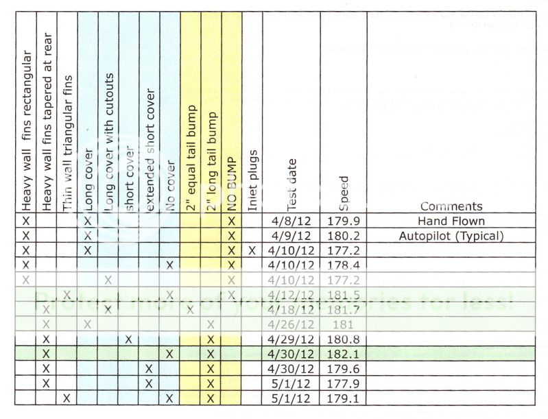
4/26/12 Test Report
After working on this for ~ 30 hours to get it ready for the race tomorrow (please note this is for a immediate need - not a science project) I flew a late afternoon test in calm surface wind and clear sky conditions. The speed was 181.0 kts per the NTPS spreadsheet using the three leg method at 6,000 ft density altitude. That was disapointing but these results are more expected than the successes I experience. The RPM was 2720.
Temperatures were up. CHT 1 through 3 were 366, 375, 373 respectively. CHT on 4 has failed. This is a 20-30 deg. F rise across the board and is the first time I have seen any affect from work on the outlet that runs back several years. This indicates to me that the air mass flowing through the system has been reduced by the bump. The oil temp was also up to 200 which is an extreme rarity im my installation - it is almost always 180.
After the test I inspected the assembly and it was fine. There was no time to take it off and reinstall the light weight triangular flow fences so I flew to Abilene that way and I will race it tomorrow that way.
One the trip down here initially at 6,000 then at 4,000 to reduce the head wing from 60 down to 50 kts with the RPM set at 2450 I was seeing 185 KTAS on the AI slide rule function.
After arrival in Abilene I inspected the assembly again and all is well
Bob Axsom
Last edited:
Thanks Brian
I know you wish you could be here too. I haven't studied the course yet, I know it is a short ~80 mile triangular course so it will fit into the big show schedule. Shouldn't required a lot of study.
You remember the flat right main I had on the way home from Llano? Well, when I got home Thursday night from my marathon work session I had a message from one of the guys that made it possible for me to get home and to be here in Abilene tonight. He said he is bringing his family to the show tomorrow. I mean, that makes me feel humble - the guy is one the men that folks around here stand up when they want to display what a Texan is.
Bob Axsom
Good luck tomorrow Race #71
I know you wish you could be here too. I haven't studied the course yet, I know it is a short ~80 mile triangular course so it will fit into the big show schedule. Shouldn't required a lot of study.
You remember the flat right main I had on the way home from Llano? Well, when I got home Thursday night from my marathon work session I had a message from one of the guys that made it possible for me to get home and to be here in Abilene tonight. He said he is bringing his family to the show tomorrow. I mean, that makes me feel humble - the guy is one the men that folks around here stand up when they want to display what a Texan is.
Bob Axsom
Last edited:
hydroguy2
Well Known Member
......one of the guys that made it possible for me to get home and to be here in Abilene tonight. He said he is bringing his family to the show tomorrow. I mean, that makes me feel humble - the guy is one the men that folks around here stand up when they want to display what a Texan is.
Bob Axsom
Thanks great! He is probably bragging you up to his family too...."look there's Race #71, you know I helped pit crew on that plane after the last race"
")
captainrichhill
Member
Heat treated the Aluminium???
I've been following this thread and I am no way qualified to ADD to it. I was surprised that I didn't see one post after the exit farring failure that mentioned the exhaust annealing the aluminium? I think that is the right term. There are all different characteristics of aluminium based on composition and heat treating. My limited knowledge of heat treating leads me to think that the exhaust heat treated the metal to the point of being brittle and the exhaust pulses made it fail.
Anyone else feel the same? Can a different Aluminium prevent this? Can you use some of the cowl exhaust air as a cooling blanket to keep the temp of the "Hump" down? They do that inside jet engines to keep the case cooler.
Just my inexperienced $.02
Richard
David Paule
Well Known Member
Bob, it looks like the external cover in the last photo extends aft of the peak of the bump fairing. That gives you a diverging duct.
You'd be better off, I think, shortening the cover so that its aft edge is slightly forward of the peak of the bump fairing.
What happens in a subsonic diverging duct is that the same amount of air and exhaust flows past the beginning and the end every second. Since the end is larger, the flow is moving more slowly. You want the flow to go faster.
Dave
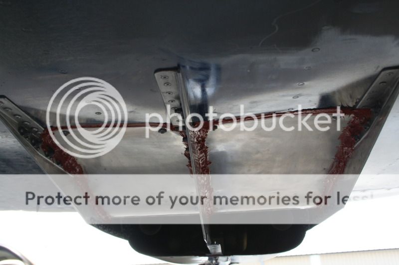
This afternoon's observations 4/28/12
I am still a bit numb from lack of sleep but I cut some roses for Jeanine then I stopped by the hangar on the way home. I didn't have the camera with me.
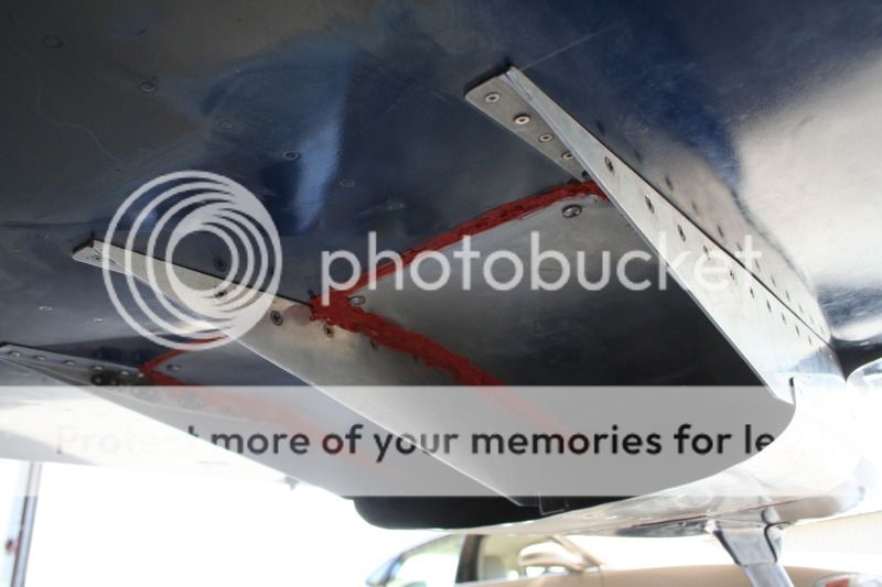
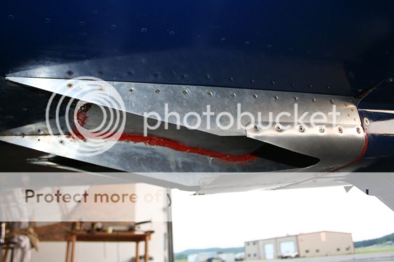
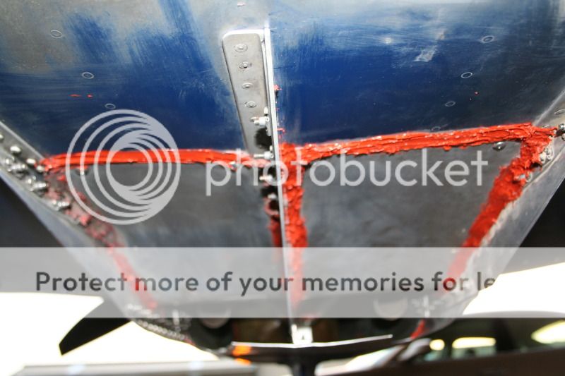
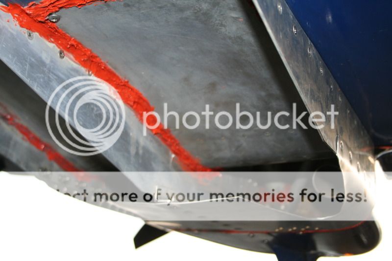
The exhaust residue is in straight line back on the bottom of the fuselage confined by the outboard flow fences outboard is clean on both sides. This indicates to me that separation from the other air surounding the airplane is occurring
The exhaust residue seems unusually thick to me.
The two outboard screws at the aft end of the bump skin are missing - BOTH OF THEM! The two inboard screws (hardware grade sheet metal screws) are inplace and appear to be tight.
the bumpt structure appears fine otherwisw.
I guess I had better take the camera back out there and post some photos. I'll be back in about an hour.
Bob Axsom
I am still a bit numb from lack of sleep but I cut some roses for Jeanine then I stopped by the hangar on the way home. I didn't have the camera with me.
The exhaust residue is in straight line back on the bottom of the fuselage confined by the outboard flow fences outboard is clean on both sides. This indicates to me that separation from the other air surounding the airplane is occurring
The exhaust residue seems unusually thick to me.
The two outboard screws at the aft end of the bump skin are missing - BOTH OF THEM! The two inboard screws (hardware grade sheet metal screws) are inplace and appear to be tight.
the bumpt structure appears fine otherwisw.
I guess I had better take the camera back out there and post some photos. I'll be back in about an hour.
Bob Axsom


David Paule
Well Known Member
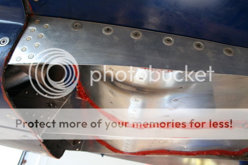
....The two outboard screws at the aft end of the bump skin are missing - BOTH OF THEM! The two inboard screws (hardware grade sheet metal screws) are in place and appear to be tight....
Looks like you've got separated flow aft of the peak of the bumps, and the turbulence and high local loads perpendicular to the bumps that are associated with that.
Dave
RV6airplanePilot
Well Known Member
Bob, is that your highest speed?
Looks like you blew right past that 185 knot barrier.
Congratulations!
Dale
RV6a KHWO
Looks like you blew right past that 185 knot barrier.
Congratulations!
Dale
RV6a KHWO
Well they corrected the results so N/G
Race # Name Aircraft Class "Elapsed Time" "Speed (MPH)" "Speed (KTS)"
Race 35 Mike Smith SX300 Sport 00:18:18.860 308.77 268.31
Race 79 Jim Robinson Glasair III Sport 00:19:18.810 292.80 254.43
Race 390 Jerry Hajek RV-8 RV Gold 00:25:24.130 222.62 193.45
Race 81 Gary Shelley RV-8 RV Blue 00:25:46.280 219.43 190.68
Race 26 Mike Thompson RV-6 RV Blue 00:26:30.500 213.33 185.38
Race 71 Bob Axsom RV-6A RV Blue 00:26:39.130 212.18 184.38
Race 77 Jim Huff Bonanza C-35 FAC4RG 00:28:49.250 196.21 170.50
Race 201 Rebecca Cutri-Kohart Mooney 201 FAC3RG 00:30:18.380 186.59 162.14
Race 03 Howard Hurlbut Bonanza FAC2RG 00:34:42.000 162.97 141.61
Race 55 Team Ely Grumman AA5A FAC5 00:36:29.380 154.97 134.67
These are my speeds not counting the BCAF (I'm going to wait for that one to settle down a bit)
Race Record (RR)# Race Date Class Aircraft Type Pilot Speed Kts Speed MPH
217 AirVenture Cup 2008 7/27/08 RV Blue RV-6A Axsom, Bob & Jeanine 194.56 223.89
782 Rocket 100, 2010 11/20/10 RV Blue RV-6A Axsom, Bob 192.80 221.87
133 Texoma 100, 2008 4/20/08 RV Blue RV-6A Axsom, Bob & Jeanine 188.36 216.80
753 Tennessee Valley Air Race 2010 10/30/10 RV Blue RV-6A Axsom, Bob 187.52 215.83
233 AirCap 200 8/24/08 RV Blue RV-6A Axsom, Bob 185.16 213.08
1213 Hill Country 150, 2012 4/21/12 RV Blue RV-6A Axsom, bob 184.97 212.86
298 Rocket 100 2008 11/23/08 RV Blue RV-6A Axsom, Bob & Jeanine 183.83 211.55
809 Taylor 150, 2011 4/2/11 RV Blue RV-6A Axsom, Bob & Jeanine 183.41 211.07
313 Taylor 100 2009 3/16/09 RV Blue RV-6A Axsom, Bob & Jeanine 182.35 209.85
1201 Taylor 150, 2012 4/14/12 RV Blue RV-6A Axsom, Bob 181.47 208.84
152 BCAF 150, 2008 5/4/08 RV Blue RV-6A Axsom, Bob & Jeanine 181.45 208.81
720 Grace Flight 2010 10/2/10 RV Blue RV-6A Axsom, Bob 181.23 208.54
1176 Texoma 100, 2012 3/31/12 RV Blue RV-6A Axsom, Bob 180.87 208.14
276 Memphis 100 2008 10/19/08 RV Blue RV-6A Axsom, Bob & Jeanine 180.26 207.44
66 AirVenture Cup 2007 7/23/07 RV Blue RV-6A Axsom, Bob & Jeanine 179.99 207.13
641 AirVenture Cup 2010 7/26/10 RV Blue RV-6A Axsom, Bob 179.83 206.94
363 Tennessee Valley Air Race 2009 6/14/09 RV Blue RV-6A Axsom, Bob & Jeanine 178.98 205.97
179 Colorado 150, 2008 6/29/08 RV Blue RV-6A Axsom, Bob & Jeanine 178.63 205.56
539 West Texas 100 6/6/10 RV Blue RV-6A Axsom, Bob 178.04 204.89
102 Memphis 100, 2007 10/28/07 RV Blue RV-6A Axsom, Bob & Jeanine 176.86 203.52
119 Rocket 100, 2007 11/18/07 RV Blue RV-6A Axsom, Bob & Jeanine 176.33 202.92
25 Wichita 300 7/17/07 RV Blue RV-6A Axsom, Bob & Jeanine 169.91 195.53
17 Taylor 100 2007 5/20/07 RV Blue RV-6A Axsom, Bob & Jeanine 168.72 194.16
Looks like you blew right past that 185 knot barrier.
Congratulations!
Dale
RV6a KHWO
Race # Name Aircraft Class "Elapsed Time" "Speed (MPH)" "Speed (KTS)"
Race 35 Mike Smith SX300 Sport 00:18:18.860 308.77 268.31
Race 79 Jim Robinson Glasair III Sport 00:19:18.810 292.80 254.43
Race 390 Jerry Hajek RV-8 RV Gold 00:25:24.130 222.62 193.45
Race 81 Gary Shelley RV-8 RV Blue 00:25:46.280 219.43 190.68
Race 26 Mike Thompson RV-6 RV Blue 00:26:30.500 213.33 185.38
Race 71 Bob Axsom RV-6A RV Blue 00:26:39.130 212.18 184.38
Race 77 Jim Huff Bonanza C-35 FAC4RG 00:28:49.250 196.21 170.50
Race 201 Rebecca Cutri-Kohart Mooney 201 FAC3RG 00:30:18.380 186.59 162.14
Race 03 Howard Hurlbut Bonanza FAC2RG 00:34:42.000 162.97 141.61
Race 55 Team Ely Grumman AA5A FAC5 00:36:29.380 154.97 134.67
These are my speeds not counting the BCAF (I'm going to wait for that one to settle down a bit)
Race Record (RR)# Race Date Class Aircraft Type Pilot Speed Kts Speed MPH
217 AirVenture Cup 2008 7/27/08 RV Blue RV-6A Axsom, Bob & Jeanine 194.56 223.89
782 Rocket 100, 2010 11/20/10 RV Blue RV-6A Axsom, Bob 192.80 221.87
133 Texoma 100, 2008 4/20/08 RV Blue RV-6A Axsom, Bob & Jeanine 188.36 216.80
753 Tennessee Valley Air Race 2010 10/30/10 RV Blue RV-6A Axsom, Bob 187.52 215.83
233 AirCap 200 8/24/08 RV Blue RV-6A Axsom, Bob 185.16 213.08
1213 Hill Country 150, 2012 4/21/12 RV Blue RV-6A Axsom, bob 184.97 212.86
298 Rocket 100 2008 11/23/08 RV Blue RV-6A Axsom, Bob & Jeanine 183.83 211.55
809 Taylor 150, 2011 4/2/11 RV Blue RV-6A Axsom, Bob & Jeanine 183.41 211.07
313 Taylor 100 2009 3/16/09 RV Blue RV-6A Axsom, Bob & Jeanine 182.35 209.85
1201 Taylor 150, 2012 4/14/12 RV Blue RV-6A Axsom, Bob 181.47 208.84
152 BCAF 150, 2008 5/4/08 RV Blue RV-6A Axsom, Bob & Jeanine 181.45 208.81
720 Grace Flight 2010 10/2/10 RV Blue RV-6A Axsom, Bob 181.23 208.54
1176 Texoma 100, 2012 3/31/12 RV Blue RV-6A Axsom, Bob 180.87 208.14
276 Memphis 100 2008 10/19/08 RV Blue RV-6A Axsom, Bob & Jeanine 180.26 207.44
66 AirVenture Cup 2007 7/23/07 RV Blue RV-6A Axsom, Bob & Jeanine 179.99 207.13
641 AirVenture Cup 2010 7/26/10 RV Blue RV-6A Axsom, Bob 179.83 206.94
363 Tennessee Valley Air Race 2009 6/14/09 RV Blue RV-6A Axsom, Bob & Jeanine 178.98 205.97
179 Colorado 150, 2008 6/29/08 RV Blue RV-6A Axsom, Bob & Jeanine 178.63 205.56
539 West Texas 100 6/6/10 RV Blue RV-6A Axsom, Bob 178.04 204.89
102 Memphis 100, 2007 10/28/07 RV Blue RV-6A Axsom, Bob & Jeanine 176.86 203.52
119 Rocket 100, 2007 11/18/07 RV Blue RV-6A Axsom, Bob & Jeanine 176.33 202.92
25 Wichita 300 7/17/07 RV Blue RV-6A Axsom, Bob & Jeanine 169.91 195.53
17 Taylor 100 2007 5/20/07 RV Blue RV-6A Axsom, Bob & Jeanine 168.72 194.16
Last edited:
These race speeds are a little misleading
The classic example is the 2008 AirVenture Cup. Straight line West to east with no altitude change requirements Jeanine and I did 194.56 kts in that never to be repeated opportunity.
Even in the other races that typically begin and end at the same airport you study the winds aloft for race time the night before and compare them with the race leg directions, speed and distance in climb & descent, cruise speed and you can often come up with a speed that is greater than the airplane's top speed. So the race speeds are nice to compare against the other racers in your class and even more so your own personal best race speed but they are not usable when you are trying to determine top speed. And, top speed is not a constant, little things change and performance decays. The best top speed I have measured using a consistant test method is still 184.4 kts.
Bob Axsom
Looks like you blew right past that 185 knot barrier.
Congratulations!
Dale
RV6a KHWO
The classic example is the 2008 AirVenture Cup. Straight line West to east with no altitude change requirements Jeanine and I did 194.56 kts in that never to be repeated opportunity.
Even in the other races that typically begin and end at the same airport you study the winds aloft for race time the night before and compare them with the race leg directions, speed and distance in climb & descent, cruise speed and you can often come up with a speed that is greater than the airplane's top speed. So the race speeds are nice to compare against the other racers in your class and even more so your own personal best race speed but they are not usable when you are trying to determine top speed. And, top speed is not a constant, little things change and performance decays. The best top speed I have measured using a consistant test method is still 184.4 kts.
Bob Axsom
Well this was interesting
I got the winds at the surface, 3000 and 6000 and interpolated 4 & 5K. There was an unusual wind forecast at 3000 ft roughly 190 at 25 (blowing toward 010) compared with the surface 210 at 10 and 6000's 260 at 15. The course was right turns (it turned out - lots of confusion because of a late change) with legs of 37.4 nm at 304 degrees magnetic, 14.1 at 077 and 29.4 at 144. So after working with it for a while I planned to climb to 3000 on leg 1, descend to 2,300 on leg 2 and stay there on the final leg of this unusually short course. The predicted speed was 210 mph.
On leg 1 I saw speeds in the mid 180's which was disapointing but that was what I got. When I turned on leg 2 I was ready to descend but I saw 195 kts and I knew I wasn't going to get any better than that so I stayed put. Unfortunately this was by far the shortest leg of the race. When I turned on leg 3 I descended to 2300 and locked in there and my speed dropped into the low to mid 170 kt range. My published speed was higher but I think the final speed is going to be 212 mph when they get everything corrected.
Bob Axsom
Corrected and published BCAF results
Race # Name Aircraft Class Elapsed Time Speed (MPH) Speed (KTS)
Race 35 Mike Smith SX300 Sport 00:18:18.860 308.77 268.31
Race 79 Jim Robinson Glasair III Sport 00:19:18.810 292.80 254.43
Race 390 Jerry Hajek RV-8 RV Gold 00:25:24.130 222.62 193.45
Race 81 Gary Shelley RV-8 RV Blue 00:25:46.280 219.43 190.68
Race 26 Mike Thompson RV-6 RV Blue 00:26:30.500 213.33 185.38
Race 71 Bob Axsom RV-6A RV Blue 00:26:39.130 212.18 184.38
Race 77 Jim Huff Bonanza C-35 FAC4RG 00:28:49.250 196.21 170.50
Race 201 Rebecca Cutri-Kohart Mooney 201 FAC3RG 00:30:18.380 186.59 162.14
Race 03 Howard Hurlbut Bonanza FAC2RG 00:34:42.000 162.97 141.61
Race 55 Team Ely Grumman AA5A FAC5 00:36:29.380 154.97 134.67
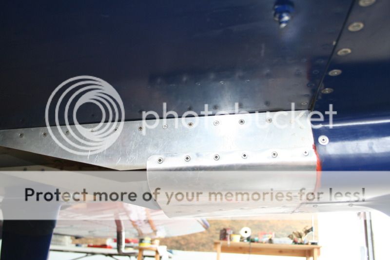
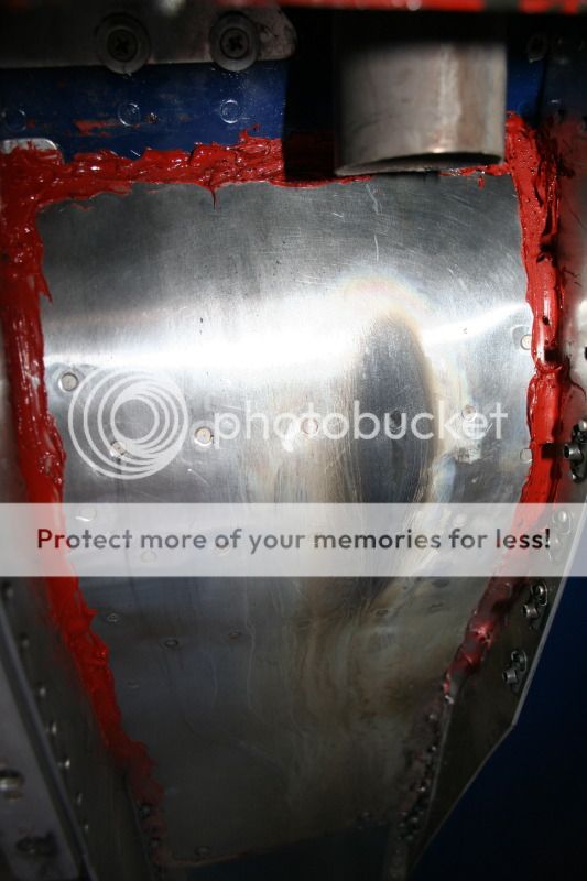
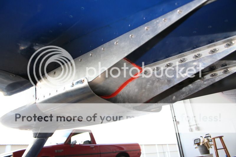
Photos with the long cover removed this afternoon 4-29-12
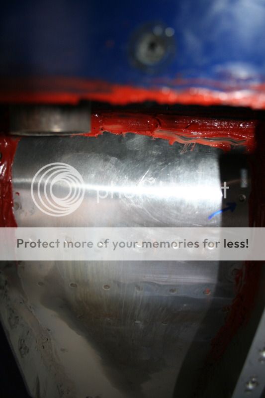
I pulled the cover off this afternoon to implement the next mod and I photographed what I saw for the record. One rivet head had popped off on the forward side of the bump, see location marked with blue arrow.

The fwd side of the bumps in both channels are clean except for the stain on the left side where the crankcase vent is directed onto the exhaust pipe.

In the center line of cover mounting holes the last one has some serious cracking but the others are fine.
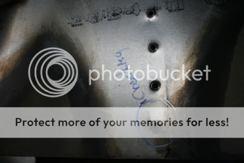
Bob Axsom
I pulled the cover off this afternoon to implement the next mod and I photographed what I saw for the record. One rivet head had popped off on the forward side of the bump, see location marked with blue arrow.
The fwd side of the bumps in both channels are clean except for the stain on the left side where the crankcase vent is directed onto the exhaust pipe.
In the center line of cover mounting holes the last one has some serious cracking but the others are fine.
Bob Axsom
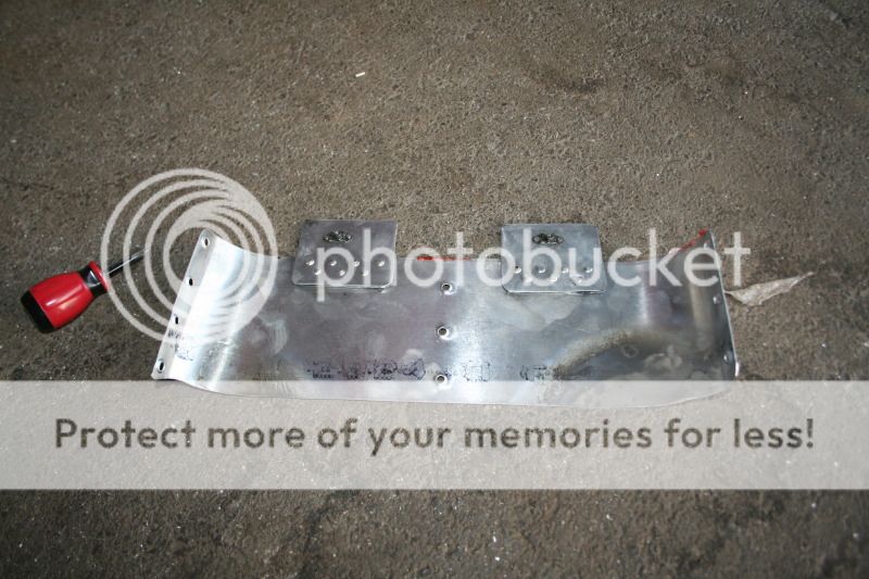
Shorten the cover
I decided to just go ahead and cut the new cover, I don't expect to use it again as is. The cover now extends back 4 3/4" from the rear of the stock cowl. That stops it a little over an inch forward of the node peak.

It looks interesting, like it has potential.
I flew the test shortly before dark this evening and the NTPS spreadsheet clculated TAS was 180.8 kts
The usable CHTs were 360, 373 and 372 for cylinders 1, 2 and 3 respectively.
I removed the cover after the flight and took some more photos to record the condition.
The condition didn't look any different that I could see than it did before the flight. But it took 1 to 2 turns to tighten one of the out board sheetmetal screws the other three sheet metal screws were tight.
The next test will be with the same fins but no cover.
If you think I made the cover too short in this configuration I can rivet an extension on and refly the test.
Bob Axsom
I decided to just go ahead and cut the new cover, I don't expect to use it again as is. The cover now extends back 4 3/4" from the rear of the stock cowl. That stops it a little over an inch forward of the node peak.
It looks interesting, like it has potential.
I flew the test shortly before dark this evening and the NTPS spreadsheet clculated TAS was 180.8 kts
The usable CHTs were 360, 373 and 372 for cylinders 1, 2 and 3 respectively.
I removed the cover after the flight and took some more photos to record the condition.
The condition didn't look any different that I could see than it did before the flight. But it took 1 to 2 turns to tighten one of the out board sheetmetal screws the other three sheet metal screws were tight.
The next test will be with the same fins but no cover.
If you think I made the cover too short in this configuration I can rivet an extension on and refly the test.
Bob Axsom
Last edited:
David Paule
Well Known Member
This was a surprise. If I've got the numbers right, this configuration gave 181.0 kts:
and this gave 180.8 kts, slightly slower:
Perhaps what it suggests is that the loss of exit velocity due to the original diverging duct, combined with forcing the exhaust to flow parallel to the airplane, causes less speed loss than the speeded-up exit air in the second, but which lets some of the exhaust plume be pointing downward, interfering with the free-stream air.
It kind of looks like the flow is now attached to the aft side of the bump, which it hadn't been before. If this is correct, kind of hard to tell, it's an improvement. On the other hand, how can it be an improvement if it's slower?
The second exit cover is about where I'd have put its trailing edge.
The only suggestions I've got for this configuration would be to add a strip to extend the cover to about the peak of the bump OR to carry it past slightly and have a lip on it that is roughly parallel to the aft face of the bump. I'd favor carrying it just to the peak of the bump rather than past.
Either way, I'd expect some cracking on the parts from the exhaust pulses.
An alternative approach would be to add exhaust pipe curved extensions to get them to lie more parallel to the bottom of the airplane - it's probably time to try this - and then set up the bump and cover to accommodate that, leaving the cover trailing edge about where it is now relative to the bump.
This business of having to think so early in the morning is tough!
Dave
Last edited:
F1Boss
Well Known Member
NEXT!
Hey Bob:
Time to straighten the exh outlets a bit, and second extend the cover to the peak of the bump. Third, the tipped lip is a good addition, in a separate experiment. You might be able to forego the exh angle change, and simply fab a slightly longer cover as your next experiment.
You are developing an exhaust augmenter which will work at both low speed (climb) and high speed (cruise). Previous attempts at such have not been successful, but yours is different from any others I have seen.
The B25 blows the exhaust along the surface of the outside of what you would call the outlet duct cover (looks a lot like cowl flaps if you ask me) and it may be this exhaust action that produces the suction in cruise....and eliminates and exhaust pulsing on a 'speed bump' as you have installed here. The exh pulses do beat up the cowl flap hinges, as these are part of the preflight check. The cover (cowl flap) and the top of the bump curve are level with each other (with the cowl flaps closed), and there is a slight gap between the top of the bump and the aft edge of the cowl flap, with a reverse bump (valley) aft the bump. I will try to get pics of that setup to you so you can give it a try too. Sure looks like someone is using the coanda principle there...using external mixing of the high velocity exh gasses to accelerate the slow moving engine cooling air?
 [/URL][/IMG]
The cowling sections with the stack exh have 'reverse scoops' covering each stack.
Post WW2 mods to the B25 have converted some of the individual stacks to a collector to increase carb heat capability. I am not referring to the collector exhaust in this discussion.
No sense in trying to re-invent the wheel!
Carry on!
Mark
This was a surprise. If I've got the numbers right, this configuration gave 181.0 kts:
image snipped
and this gave 180.8 kts, slightly slower:
image snipped
Perhaps what it suggests is that the loss of exit velocity due to the original diverging duct, combined with forcing the exhaust to flow parallel to the airplane, causes less speed loss than the speeded-up exit air in the second, but which lets some of the exhaust plume be pointing downward, interfering with the free-stream air.
It kind of looks like the flow is now attached to the aft side of the bump, which it hadn't been before. If this is correct, kind of hard to tell, it's an improvement. On the other hand, how can it be an improvement if it's slower?
The second exit cover is about where I'd have put its trailing edge.
The only suggestions I've got for this configuration would be to add a strip to extend the cover to about the peak of the bump OR to carry it past slightly and have a lip on it that is roughly parallel to the aft face of the bump. I'd favor carrying it just to the peak of the bump rather than past.
Either way, I'd expect some cracking on the parts from the exhaust pulses.
An alternative approach would be to add exhaust pipe curved extensions to get them to lie more parallel to the bottom of the airplane - it's probably time to try this - and then set up the bump and cover to accommodate that, leaving the cover trailing edge about where it is now relative to the bump.
This business of having to think so early in the morning is tough!
Dave
Hey Bob:
Time to straighten the exh outlets a bit, and second extend the cover to the peak of the bump. Third, the tipped lip is a good addition, in a separate experiment. You might be able to forego the exh angle change, and simply fab a slightly longer cover as your next experiment.
You are developing an exhaust augmenter which will work at both low speed (climb) and high speed (cruise). Previous attempts at such have not been successful, but yours is different from any others I have seen.
The B25 blows the exhaust along the surface of the outside of what you would call the outlet duct cover (looks a lot like cowl flaps if you ask me) and it may be this exhaust action that produces the suction in cruise....and eliminates and exhaust pulsing on a 'speed bump' as you have installed here. The exh pulses do beat up the cowl flap hinges, as these are part of the preflight check. The cover (cowl flap) and the top of the bump curve are level with each other (with the cowl flaps closed), and there is a slight gap between the top of the bump and the aft edge of the cowl flap, with a reverse bump (valley) aft the bump. I will try to get pics of that setup to you so you can give it a try too. Sure looks like someone is using the coanda principle there...using external mixing of the high velocity exh gasses to accelerate the slow moving engine cooling air?
The cowling sections with the stack exh have 'reverse scoops' covering each stack.
Post WW2 mods to the B25 have converted some of the individual stacks to a collector to increase carb heat capability. I am not referring to the collector exhaust in this discussion.
No sense in trying to re-invent the wheel!
Carry on!
Mark
Thanks Guys
We had thunderstorms here this morning but it is clearing up so I am going to get these new planned tests completed and decide what to do next. They all sound worth giving a shot.
I am going to the airport shortly and fly the no cover configuration with the existing extended bump.
Then I think I will replace the heavy fins with the light triangular flow fences.
It might be worth flying a naked test between the two because the conversion process takes me to that state (it's complicated involving long magnetic screwdriver and non-stainless steel screws to attach all three items to the center mount with no additional fasteners).
After that is all done the past the bump cover extension with a conforming to the aft bump angle lip seems logical then cut the aft part with the lip off fao another test.
Mark when we were checking in at Dyess in Base Ops Friday, the crew for the B-25 Devil Dog was checking in as well. We flew the race as the first event on Saturday morning and I continued the flight on home but Mike returned to base and might have some stories to share with you about their performance.
Bob Axsom
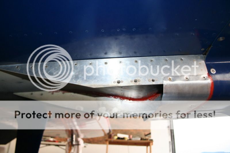
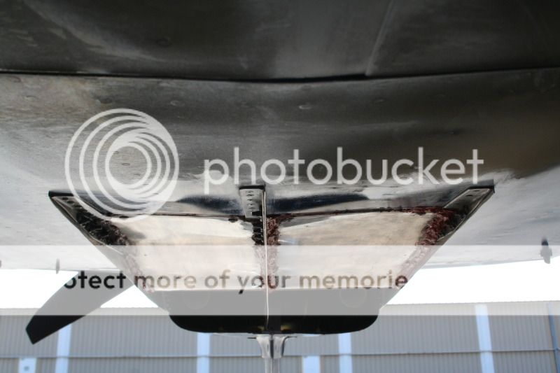
Uncovered elongated bump assembly 4-30-12
I went to the airport and flew the test as is with no wipe down but I potographed it after the flight which may be compared with the post flight photo from yesterday. Here are the two I took after the flight today:


The speed was 182.1 kts so a little faster. The center mount bracket is still there hanging in the wind so if I were to replace these three vertical units with the much cleaner triangular flow fences it should be even faster.
I have rethought my test sequence. I'm going to do the two with the modified cover while the hard cover mount structure is still there then the naked and the triangles with the bumps.
Bob Axsom
I went to the airport and flew the test as is with no wipe down but I potographed it after the flight which may be compared with the post flight photo from yesterday. Here are the two I took after the flight today:
The speed was 182.1 kts so a little faster. The center mount bracket is still there hanging in the wind so if I were to replace these three vertical units with the much cleaner triangular flow fences it should be even faster.
I have rethought my test sequence. I'm going to do the two with the modified cover while the hard cover mount structure is still there then the naked and the triangles with the bumps.
Bob Axsom
johnny stick
Well Known Member
summary
Bob,
This a great thread. Could you summarize the baseline and different options you have tried and the resulting speed change?
Thanks
Johnny Stick
Bob,
This a great thread. Could you summarize the baseline and different options you have tried and the resulting speed change?
Thanks
Johnny Stick
johnny stick
Well Known Member
Summary data
Bob,
I understand your reluctance to post preliminary data, especially since it was very hard and expensive to obtain. I am just curious how much extra speed you have obtained. Must be significant. Would you be willing to label the data something like: baseline, option 1, option 2, etc? without details of what the different options mean or the order they were tested? I am not a racer, I do not have an RV flying in the near future, but I really enjoy your true grass roots research. I can't help but think your work has yielded a wealth of data just by having different data than expected, even if the speed has not increased significantly . Thanks for all you do.
The lengthend cover to the bump high point configuration
These are post flight photos.


I completed this mod at around 7:30 pm and I had to really rush to get a test in and be on the ground before dark. Even in the rushed state I think I followed the test method. The speed was 179.6 kts but it has been suggested that these last minute before dark tests might provide distorted results because of sinking air. I don't really want to waste any more time on this but if the weather is good when I get out there, I'll refuel and do it over.
Bob Axsom
These are post flight photos.
I completed this mod at around 7:30 pm and I had to really rush to get a test in and be on the ground before dark. Even in the rushed state I think I followed the test method. The speed was 179.6 kts but it has been suggested that these last minute before dark tests might provide distorted results because of sinking air. I don't really want to waste any more time on this but if the weather is good when I get out there, I'll refuel and do it over.
Tuesday: A 30 percent chance of showers and thunderstorms before 1pm. Cloudy, then gradually becoming mostly sunny, with a high near 82. Breezy, with a south wind 10 to 15 mph increasing to between 20 and 25 mph. Winds could gust as high as 35 mph. New rainfall amounts between a tenth and quarter of an inch, except higher amounts possible in thunderstorms.
Bob Axsom
Last edited:
Repeated last night's test flight and a new configuration
Last nights configuration was slow again today 177.9 kts.
Then I removed the cover and the three heavy fins and installed the three light triangular fins with the long tail bumps.
Latest configuration before the test flight:

Same configuration after the flight:
It was faster but still slow 179.1
It is time to study what has been revealed and refine the direction.
Bob Axsom
Last nights configuration was slow again today 177.9 kts.
Then I removed the cover and the three heavy fins and installed the three light triangular fins with the long tail bumps.
Latest configuration before the test flight:
Same configuration after the flight:
It was faster but still slow 179.1
It is time to study what has been revealed and refine the direction.
Bob Axsom
Last edited:
Here is what I came up with
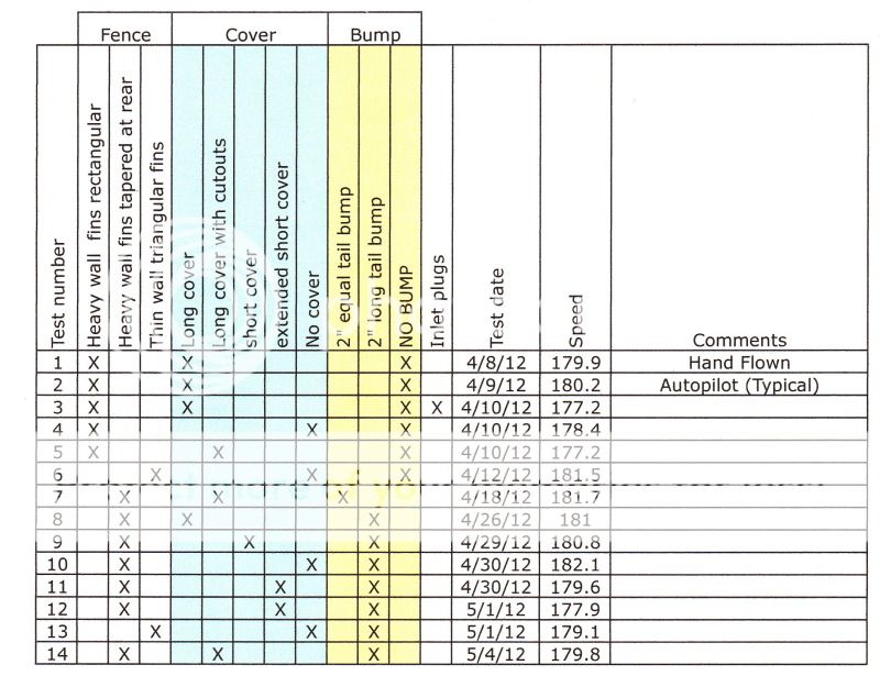
At first I said:
Then I started high lighting rows and columns and I noticed and increase and decrease in speed related to the restriction in the outlet path. The correlation is not obvious in absolute speed numbers but there is some error margin in the test method, the test sequence is not perfect and the test configurations are not exhaustive.
Note these examples:
This is where it gets tight, I have flown the stock configuration outlet with a few more race preps at 184.4 kts and I want something better than that. It seems like a good idea at some point to fly the plane without any outlet mods installed to establish a comparable baseline then target small improved flow mods to attempt to exceed that new baseline. At this time, on our airplane, it seems to me that the cover is a speed limiting device - could be wrong. My inclination right now is favoring the flow fences and the bump in some form.
Bob Axsom
At first I said:
I went through the anotated NTSP spreadsheets and attached notes I collected during this effort and I saw no mod that showed up consistently in the higher speed results. I still think there is something to be gained by working with the cooling air outlet as others have been successful in doing - I just haven't found it yet. The cover extending the outlet parallel with the bottom of the fuselage to get the cooling air aligned with the flight path before releasing it; the bump in search of the Coanda effect to turn the air back up parrallel with the bottom of the fuselage; the flow fences to minimize the turbulent air recombination aft of the outlet; the confinement of the exhaust into chambers with the cooling air outlet for a pumping action to accellerate the air flow through the engine cooling system; and efforts to best position the trailing edge of the outlet cover with the "bump" for some improved performance have revealed little in this gross search. I think it is there but it does not appear to be a very big performance enhancement and it will take finer work than I have done so far to identify it.
I feel that the use of the "bump in the outlet path was demonstrated to restrict the cooling air mass flow in these tests and the immediate jump to a 2" bump, trying no other height, may be too limited an unfocused to learn much other than that. I was disappointed that I did not see an aircraft speed increase resulting from the reduced cooling air mass flow indicated by the CHT increase.
The test configuration on 4-19-12 with the two chambers formed by the fins and the cover and no bump has possibilities that I plan to explore. I'm thinking of putting that back on with a new cover with a ground adjustable closure ramp on the back and test fly with changes to the opening on successive flights.
The more I look at the matrix the more interesting observations I make. More thought required.
Then I started high lighting rows and columns and I noticed and increase and decrease in speed related to the restriction in the outlet path. The correlation is not obvious in absolute speed numbers but there is some error margin in the test method, the test sequence is not perfect and the test configurations are not exhaustive.
Note these examples:
1) The two thin wall triangular fin tests on 4/12/12 and 5/1/12 - the cunfiguration with no bump in the flow path is faster.
2) The two thick wall tapered trailing edge fin configuration tests on 4/18/12 and 4/26/12 is an imperfect comparrison because the 2" equal tail bump was destroyed in the race at Llano on 4/21/12. However, if you consider that both have a 2" bump restricting the flow and the one with the long cover is slower than the one with the cutout (back pressure relieved?) cover. That seems consistent with the thought. One might say that the test with the short cover on 4/29/12 should be faster than the identical configuration except for the long cover tested on 4/26/12 and I say 0.2 kt difference is too close to call with the error margin in this test method and the rounding in the NTPS spreadsheet calculations.
3) The first five tests have a conflict with this idea. The first two test speeds were too high to fit this relationship but if you look at the other three the interrelationship is clear. plugs in the inlet slowest, plugs and cover removed = faster, install vented cover = slower.
This is where it gets tight, I have flown the stock configuration outlet with a few more race preps at 184.4 kts and I want something better than that. It seems like a good idea at some point to fly the plane without any outlet mods installed to establish a comparable baseline then target small improved flow mods to attempt to exceed that new baseline. At this time, on our airplane, it seems to me that the cover is a speed limiting device - could be wrong. My inclination right now is favoring the flow fences and the bump in some form.
Bob Axsom
Last edited:
There was a configuration that wasn't tested
On 4-18-12 I tested the short tail bump using the development cover with exhaust cutouts and got 181.7 kts. Then I replaced it with the new replacement long cover with the equal length tail bump configuration still in place.
I quicky flew the night before just to verifly it was OK then went to Llano, TX for the race. This is the configuration that I found shattered after the race but during that race I caught, passed and beat the SARL record holding FAC1RG Bonanza S35 which had beaten me the last couple of times. I'm thinking I should fabricate duplicates out of Stainless Steel and test that configuration. I'm thinking the long tail on the current bump "may" not be as good as the more curved surface. It makes sense to me that if the Coanda effect exists removing the curve would remove the effect.
I still have the old development cover with the cutouts - maybe I should test with it and see if I can duplicate the 181.7 speed.
Bob Axsom
Last edited:
kentb
Well Known Member
Bob, I like what your doing.
You have inspired me to do some experimenting on my own this summer.
For now I am working on some ideas to do on my 9A
I was looking at your last picture and noticed that the outside of your cowl and exit tunnel aren't smooth in the corner. You might gain some here by smoothing this. Green area
Also (forgive my drawing) have you tried extending the cover back and up towards the fuse? Yellow areaPlease be advised that I have no skills as an aeronautical engineer.

Kent
Last edited:
Yes I did
I had to do that to get the density altitude but my temperatures are always low as a by-product of all the lower cowl baffling I developed in there several years ago. These mods made my temperatures go up to more normal levels. I don't think this would help in that way. I could be wrong, depending on how you work it I guess but for me the temperatures went up 20-30 degrees F with these mods.
Bob Axsom
johnny stick
Well Known Member
Awesome work
Bob,
Awesome work. I think this thread will be referred to in the future for a long time. There is a lot of important data here. I think repeating the baseline test is a very good idea. I know I have learned a lot through your experimentation. Thank you for all you have done.
Bob,
Awesome work. I think this thread will be referred to in the future for a long time. There is a lot of important data here. I think repeating the baseline test is a very good idea. I know I have learned a lot through your experimentation. Thank you for all you have done.
A couple of thoughts at this point 15:35Z 5-3-12
I ordered some 0.016" stainless steel sheet from Aircraft Spruce to support one thought to replicate the bumps that were fast, untested but shattered in the race at Llano, TX.
I am also giving a lot of thought to reducing the height of the bumps but this requires a lot of thought because of the mounting. The idea behind this is the restriction with the existing configuraton has been shown th raise the CHTs AND slow the airplane down. I had similar experience when trying additional an bulkhead/baffle in the lower cowl to block leaks forward around the propshaft between the cowl and spinner and separately, lower flow directing baffles to turn the air toward the outlet. Both of those extensive efforts reduced the space for the cooling air mass flow and I believe, restricted the cooling air mass flow. The airplane slowed down instead of speeding up as planned. In each case the speed came back when the new baffles were removed. I think I am seeing a similar effect on speed from the outlet restriction without reducing the lower cowl volume.
Test results that I have given a lot of thought to were the tests with no cover and no bump and the corresponding no cover with bump tests using both flow fence configurations (4 test flights).
Long ago I established that the error margin could be as great as plus or minus 2 kts but you can't discard everything you don't immediately understand as normal variations associated with the test method and not the item under test. I studied the photographs and I think the small triangular flow fences taper down too close to the peak of the bumps to provide an effective boundary and the effect of the bump is lost. Here are four comparable photographs:

They are not perfectly comparable but you can see the difference I think. They give me a reason for the opposite reaction to the installation of the bump. It would be interesting to see the small triangular fin configuration performance with smaller height bumps.
There is an existing configuration that I haven't flown with the 2" long tail bump that is the covered case with exhaust cutouts. I think I will fly it and collect that data first then start some tests with different bumps. Any change of the pumps or flow fences is an awkward and time consuming task because of the RTV.
Back to work.
Bob Axsom
I ordered some 0.016" stainless steel sheet from Aircraft Spruce to support one thought to replicate the bumps that were fast, untested but shattered in the race at Llano, TX.
I am also giving a lot of thought to reducing the height of the bumps but this requires a lot of thought because of the mounting. The idea behind this is the restriction with the existing configuraton has been shown th raise the CHTs AND slow the airplane down. I had similar experience when trying additional an bulkhead/baffle in the lower cowl to block leaks forward around the propshaft between the cowl and spinner and separately, lower flow directing baffles to turn the air toward the outlet. Both of those extensive efforts reduced the space for the cooling air mass flow and I believe, restricted the cooling air mass flow. The airplane slowed down instead of speeding up as planned. In each case the speed came back when the new baffles were removed. I think I am seeing a similar effect on speed from the outlet restriction without reducing the lower cowl volume.
Test results that I have given a lot of thought to were the tests with no cover and no bump and the corresponding no cover with bump tests using both flow fence configurations (4 test flights).
big fences no cover no bump = 178.4 kts
big fences no cover 2" long tail bump = 182.1 kts
small triangular fences no bump = 181.5 kts
small triangular fences 2" long tail bump = 179.1
big fences no cover 2" long tail bump = 182.1 kts
small triangular fences no bump = 181.5 kts
small triangular fences 2" long tail bump = 179.1
Long ago I established that the error margin could be as great as plus or minus 2 kts but you can't discard everything you don't immediately understand as normal variations associated with the test method and not the item under test. I studied the photographs and I think the small triangular flow fences taper down too close to the peak of the bumps to provide an effective boundary and the effect of the bump is lost. Here are four comparable photographs:
They are not perfectly comparable but you can see the difference I think. They give me a reason for the opposite reaction to the installation of the bump. It would be interesting to see the small triangular fin configuration performance with smaller height bumps.
There is an existing configuration that I haven't flown with the 2" long tail bump that is the covered case with exhaust cutouts. I think I will fly it and collect that data first then start some tests with different bumps. Any change of the pumps or flow fences is an awkward and time consuming task because of the RTV.
Back to work.
Bob Axsom


Long cover with cutouts long tail 2" bump test
Tested this afternoon 179.8. A little more than 1.5 kts slower than the same configuration with the short tail 2" bump. Aircraft Spruce shipped the Stainless Steel for a possible replacement . The previous aluminum short tail bump shattered in flight. The vent tube oil flow appears straight (no swirl etc.).

Bob Axsom
Tested this afternoon 179.8. A little more than 1.5 kts slower than the same configuration with the short tail 2" bump. Aircraft Spruce shipped the Stainless Steel for a possible replacement . The previous aluminum short tail bump shattered in flight. The vent tube oil flow appears straight (no swirl etc.).
Bob Axsom
Last edited:
Kevin Horton
Well Known Member
Bob,
Have you ever tested the exact same configuration multiple times on different days to see how much scatter there is in the results?
I'm betting you would find a kt or two of scatter, which means that perhaps you need more than one test point on one flight to decide whether a change has given a small speed increase or not.
Why not fly a couple more tests on different days with your current configuration?

