What's new
Van's Air Force

Don't miss anything! Register now for full access to the definitive RV support community.

G3X and Hall Effect device

I am looking for an "easy" way to install a shunt on my -14 battery. g3x system. I have the VPX so no need for main system sensing - just the health and status of the battery.


For a G3X expert, does the shunt have to be on the (+) side of the battery? Chris over at Stein thought the Garmin 900 series had a shunt on the Battery Ground cable and I am wondering could I do that on the g3X? That way it is not always hot and slowly draining the battery as well as having hot wires behind the panel all the time.


I am trying to avoid breaking into the neat buss bar already set up on the -14 between the main contactor and starter solenoid as this is where I have the B leads from both ALT tying into the system.


Option 2 is a Hall effect device on the (+) battery cable - but the AMP Key 100 garmin specifies is +4.5 VDC to +10VDC range Needless to say I am +14VDC........


Thoughts?


Thanks
Mark
 
I put a shunt in the normal place but I also put a hall sensor on the wire inside the firewall. The hall sensor will show actual ship loads from the battery if the primary alternator fuse opens or the shunt fails. Also did it for the fun of having it. Works great as described. The hall sensor isn?t very cheap but real convenient. It probably would saturate in a non critical way on the battery groundwhen the starter is cranked and be inaccurate for that.
 
IThat way it is not always hot and slowly draining the battery as well as having hot wires behind the panel all the time.
Thanks
Mark

The shunt does not create a drain on the battery. It only steals a TINY amount of current when the circuit is flowing current. It takes nothing when the device it is connect to (GEA24) is powered down.

Larry
 
Also the hall ring gets its power from the GEA24 so the power to it is in spec. It doesn?t take a bus connection.
 
The 4.5 to 10 volt is its output voltage and the g3x can read that fine. I installed a hall effect sensor on the firewall using the existing adel clamp (upsized to a -25) for the wire inbetween the battery and master contactor. It should work as an ammmeter showing current in both directions.
 
GEA 24 Hall Effect Sensor

I am looking for an "easy" way to install a shunt on my -14 battery. g3x system. I have the VPX so no need for main system sensing - just the health and status of the battery.


For a G3X expert, does the shunt have to be on the (+) side of the battery? Chris over at Stein thought the Garmin 900 series had a shunt on the Battery Ground cable and I am wondering could I do that on the g3X? That way it is not always hot and slowly draining the battery as well as having hot wires behind the panel all the time.


I am trying to avoid breaking into the neat buss bar already set up on the -14 between the main contactor and starter solenoid as this is where I have the B leads from both ALT tying into the system.


Option 2 is a Hall effect device on the (+) battery cable - but the AMP Key 100 garmin specifies is +4.5 VDC to +10VDC range Needless to say I am +14VDC........


Thoughts?


Thanks
Mark

We use the #3 and #4 General purpose inputs on the GEA 24 for Hall effect transducers. The GEA 24 provides 5V supply voltage directly to the Hall effect unit. The AMPLOC KEY100 outputs 2.5V at zero amps, with a sensitivity of 15.9 mV/Amp up to +/- 100 A. There is an interconnect drawing that details this interface on page 30-4 of the AL Revision of the G3X Touch Installation Manual.

If using a shunt to monitor the battery, our recommendation is to mount the shunt between the positive (+) terminal and the battery contractor.

Thanks,

Justin
 
Old thread, but seemed like a good place to post this as it's often asked. For KEY100 (Amploc) hall sensors, connecting to the G3X, a good connector is the Molex 5051-03 connector (newer part number is 22-01-1032). Available here. Use the Molex 2759 series pins; I use the gold plated ones

Just about any 3 circuit connector with a 2.5mm pitch will work, but I know that the Molex connectors will latch to the sensor, others may not.
 
Last edited:
Amploc current sensors

I have an application where I want to monitor lower amp draws and don't want to use a shunt that might get damaged rendering my fuel pumps inoperative. I want to use a hall effect current sensor. The Amploc Key100 seems to be the go-to sensor used (I have Garmin G3X systems). Amploc makes another series called the Amp and Pro25. I believe either will work? Anyone have any experience with them? I want to be able to understand if I have a prefilter (before the fuel pump) clogging (There will be a 1-amp reduction when that occurs) or if the post filter (After the fuel pump) starts to clog as their will be a 2-amp increase. Normal amp draw 5 amps. The PRO25 seems to have better sensitivity. I'm assuming I could loop the power line around the coil twice and change the range settings to further improve the sensitivity? Thanks
 
The G3X system is set up for Amploc KEY100 sensors, so that is what I would probably use since it is known to work. If you want more sensitivity for smaller maximum currents, you can loop the wire through a few times and adjust the sensor scale factor calibration accordingly.
 
How many loops?

Matt, as always appreciate the input. Since I’m looking to sense in 5 amp range with maximum 10 amps, any reason not to loop 10 times for the Key100 ? Thanks
 
Matt, as always appreciate the input. Since I’m looking to sense in 5 amp range with maximum 10 amps, any reason not to loop 10 times for the Key100 ? Thanks

I don't see why not. Although, now that I look at the manufacturer's datasheets, I think you actually could also use something like an AMP25 which would give you increased sensitivity. The two main constraints are that your sensor has to have a 2.5V output at 0A, and you have to know the mV/A scale factor. Not having tried it myself, I can't say for sure if it will work, but it seems reasonable.
 
AMPLOC Hall Sensor Bracket

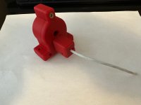
I wanted to mount AMPLOC hall sensors on my firewall. I 3D printed a complete housing for the sensor that also secures the Molex connector and provides stress relief. Her is a pix of the bracket. The STL files can be found here: https://rv10.ca/3d-printed-stuff/
 

Attachments

  • IMG_6387-2.jpg
    IMG_6387-2.jpg
    509.4 KB · Views: 33
Last edited:
I wanted to mount AMPLOC hall sensors on my firewall. I 3D printed a complete housing for the sensor that also secures the Molex connector and provides stress relief. Her is a pix of the bracket. The STL files can be found here: https://rv10.ca/3d-printed-stuff/

Excellent work, always a little surprised AMPLOC don’t provide some mounting points or a holder of some kind for the products. Thanks for sharing the STL file.
 
I wanted to mount AMPLOC hall sensors on my firewall. I 3D printed a complete housing for the sensor that also secures the Molex connector and provides stress relief. Her is a pix of the bracket. The STL files can be found here: https://rv10.ca/3d-printed-stuff/

Very much appreciated and the link to the Control Approach pedal gust lock is great as well. Thanks for your contributions to the community and especially the SDS testing you do.
 
Back
Top