What's new
Van's Air Force

Don't miss anything! Register now for full access to the definitive RV support community.

Red Cube - Located Over Fuel Servo

laserman

Active Member
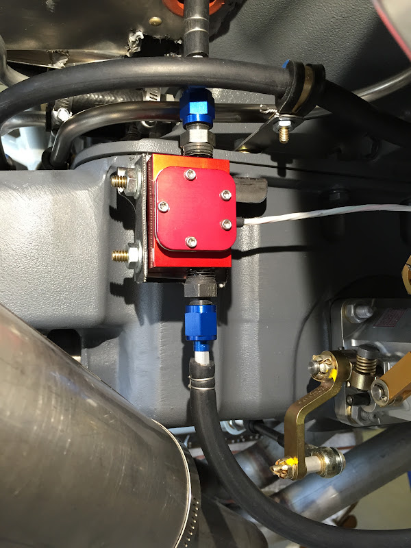
I'm sure "Red Cubes" have been located above the Throttle Body before.. I just have not seen pics posted here. All throttle linkages easily clear hoses. Cable supported by only by hoses. Hoses secured against excessive movement by clamps.. A soft rubber grommet was placed between cube and engine to "Tighten" up the overall installation. Permatex HP thread sealant used. None on first few threads - Steel fittings for fatigue resistance. All the installation rules seem to be met... (?)

(First time Poster to forum.)

Thanks Alan.


Cube1:

Cube1 by Arthur Karpinski, on Flickr

Cube2:

Cube2 by Arthur Karpinski, on Flickr

Hoses:

Hoses by Arthur Karpinski, on Flickr
 
Last edited:
Something Similar

I was thinking about doing something very similar. I'd be interested to hear feedback from more knowledgeable folks.

Brian
 
The cube is fine, but don't tyrap the wire to the governor line. Tie it to the hose. No tyraps on the gov line please.
 
We've seen them in everyplace you can imagine, and some that you cant imagine. I dont recall anyone having any issues. Between the servo and flow divider seems a great place. Vans puts the cube between the pump and the servo on the RV14 install.
Tom
 
I like your solution

but I saw it after making this. It is a 4130 bracket with a "U" shaped piece of baffle material. It decouples high frequency engine vibrations but restrains the cube from large motions.

IMG_1911.jpg


It is mocked up so The hose lengths were known exactly. The large black hose is temp for the starter wire run.

There is a video of how it moves if you want it email me.
 
Bill & Lazerman,
I am also installing my Red Cube in a manner similar to yours. But as looking at your photos I noticed that you have a SS governor line. Would it be possible that you have the part number and pictures of the installation near the alternator? I bought a line for my engine but it won't clear the alternator. Mine is a boss mounted from B&C. Any help would be appreciated.
 
Off Topic, so - - - started

Bill & Lazerman,
I am also installing my Red Cube in a manner similar to yours. But as looking at your photos I noticed that you have a SS governor line. Would it be possible that you have the part number and pictures of the installation near the alternator? I bought a line for my engine but it won't clear the alternator. Mine is a boss mounted from B&C. Any help would be appreciated.

New Thread on alternator clearance specifically.

http://www.vansairforce.com/community/showthread.php?p=1074670#post1074670
 
but I saw it after making this. It is a 4130 bracket with a "U" shaped piece of baffle material. It decouples high frequency engine vibrations but restrains the cube from large motions.

IMG_1911.jpg


It is mocked up so The hose lengths were known exactly. The large black hose is temp for the starter wire run.

There is a video of how it moves if you want it email me.

Doesn't the instructions for the red cube indicate that it should be oriented so the electrical lines exit the top of the cube and that fuel flow downward as it exits the cube?
 
Doesn't the instructions for the red cube indicate that it should be oriented so the electrical lines exit the top of the cube and that fuel flow downward as it exits the cube?

Nope, how is it going to purge bubbles if flow is counter to the bubbles?
 
Red Cube Location Floating on Fuel Lines, not mounted

Question about mounting or locating the Red Cube. Installing engine now.
So it appears from the directions and posts that the Red Cube can be mounted or just hanging in-line on the fuel hose. I guess this is called floating mount on the fuel line.

So do you think it is okay to mount cube directly off the fuel pump output AN fitting (IO 360 with Horizontal Induction) and the fuel hose that then goes to Throttle body? This puts it about same altitude as the Throttle body input so no low spots. The fuel pump is secure and I can clamp the fuel line to the engine mount within about 6 inches of the Red Cube. And I can get an AN flared female to 1/4 NPT 90 degree elbow so the connection to the pump is secure.

Will this work? Seems like it would shake around with the engine a lot more than if mounted to firewall, but does that matter?
 
For the same reason that the oil pressure sensor is not mounted directly to the engine, I would not choose to directly mount the red cube to the pump or servo with an AN or other pipe fitting. Use a flexible hose between the vibration source (engine) and the weight (red cube).
 
Last edited:
So do you think it is okay to mount cube directly off the fuel pump output AN fitting (IO 360 with Horizontal Induction) and the fuel hose that then goes to Throttle body?

Bad idea +1. And it may not be very accurate there when the boost pump is on. Best location is in the line between the throttle body outlet and the fuel divider.
 
Bad idea +1. And it may not be very accurate there when the boost pump is on. Best location is in the line between the throttle body outlet and the fuel divider.

Dan is right. I've seen builders mount Flowscans and Red Cubes there and they are not very accurate at all. They need to be between the servo and divider. I prefer to mount them level.
 
Just another data point for those contemplating locations. Inside the engine compartment is not the only location that works well. In fact there are some drawbacks to mounting near the engine. Such as vibration, heat issues. I have my cubes (yes two of them, one for return fuel lines) mounted on the cold side of the firewall in line after the fuel filter before the lines go through the firewall. 400 hours, accurate to a "T" and no vibration or heat issues to contend with at all.

Just throwing it out there as something to consider.
 
On my carb'd installation, I have it mounted on a bracket that's vibration-isolated from the cross-bar that goes between the tops of the two landing gear tubes on the RV-6 engine mount. I never did take a photo. Wire is pointing up, but I did use 45 degree fittings on each end of the cube to route wires better. Readings in this location are affected by the boost pump being on, but apparently it's such a short portion of my flight that it doesn't affect the fuel totals recorded in my MGL fuel gauge. I can look at the gauge, see what i've burned, and see exactly that number on the fuel pump when I fill up.

If I were to do it all over again, i'd put one red cube in each wing root at the exit of the fuel tank, and not install fuel senders in the tanks at all. The fuel counter (based on flow through the red cube) in the MGL gauge is more accurate than the senders.
 
Steve long list of locations and orientations of red cubes. "Some" have even sparked some lively conversations here on VAF! There does seem to be more accurate readings between the servo and flow divider, and EI does prefer the electrical wires to be 'up' and not 'down. Sideways---well I guess thats another 'lively conversation', but in the location near the flow divider, with the wires exiting sideways, cube vertical, seems to work very well. (We've redesigned our setup to use a hose on the cube outlet versus a rigid fitting connection.)

Not everyone will plumb their's the same, so think about what works for you. if you need pics, we can help.
Tom
 
Question. I know the recommended location is on the pressure side of the engine fuel pump (after all fuel pumps). Is it just a choice having the cube between the bendix and spider vs just past the pump, or is there some distinct advantage.
 
Question. I know the recommended location is on the pressure side of the engine fuel pump (after all fuel pumps). Is it just a choice having the cube between the bendix and spider vs just past the pump, or is there some distinct advantage.

The people I have spoken with that have the cube between boost and engine pump say they get an indication change when the bost pump is on. It is a small sample of craft so I dont know if it is across the board. Mine is between engine pump and servo and it is undesturbed by boost pump actuation. I cant speak to the position between servo and spider although there is good commentary here on VAF about that location.
 
Red Cube Location

Thanks to all this info. I've decided to mount the Red Cube in the -4 line going up to the divider from the servo. This is right above the servo (throttle body) just like the photos at the beginning of this thread. I also got clarification from Electronics International Inc that this is a good place and meets there requirements.

Note though I think I should use aluminum fittings in the cube rather than steel because there are flex lines on both input and output and then no dis similar metals.

I had originally planned on the firewall, then hanging from the pump, but this location seems best. Now I've gotta go order some flex hose and fittings. I will try to modify the existing -4 hose. It just needs to be a little shorter.

Thanks to this terrific forum.
 
Bad idea +1. And it may not be very accurate there when the boost pump is on. Best location is in the line between the throttle body outlet and the fuel divider.

I'm with Dan on this one. I have my Floscan between the servo and the fuel divider (mild uphill flow) with relatively straight hose either side. Accuracy is phenomenal (1 litre max error in 160 litres). All my friends with the flow transducer between the boost pump and the mechanical pump have serious errors when the boost pump is on. Putting the transducer between the boost and mechanical pumps is the easiest installation and that's why so many put it there....but it's the most inaccurate location.
 
I'm at both ends of the spectrum with my two installations. The Rocket has the Floscan attached directly to the flow divider with a short NPT nipple (fed by hardlines, btw), while the -8 has the transducer on the cold side of the firewall between the boost and engine driven pump. The -8 shows a 5 GPH increase with the boost pump on, the Rocket is immune. Both are very accurate at the tank fill, however. While overall indication performance is acceptable, I really do not like having the incredibly restrictive transducer on the suction side of the fuel system. I know plenty of people get away with it, but after looking at the miniscule passage in the transducer, I think it is just bad practice to have it upstream of the pumps. I'll not install one there again if I have another option.
 
The main reason to not mount the transducer between the boost pump and engine driven pump is the because the boost pump can create a hammering affect against the engine driven pump when turned on. This causes the impeller in the transducer to be pulsed forward and backward quickly which is counted by the instrument as increased fuel flow.
An additional concern, while we have never seen it, is the possibility of vapor lock. The transducer was not designed for fuel to be sucked through it. It was designed for fuel to be pushed through it.
It is best if installed with the wires pointing up, as that is where the transducers were tested. However, ease of installation should take precedence. Flexible like should ALWAYS be used to provide vibration protection and the output port should not be pointing down. Installing the transducer in such a way can trap air bubbles and cause erratically high fuel flow readings due to the optical sensor seeing refracted signals.
 
Last edited:
fuel hoses

but I saw it after making this. It is a 4130 bracket with a "U" shaped piece of baffle material. It decouples high frequency engine vibrations but restrains the cube from large motions.

IMG_1911.jpg


It is mocked up so The hose lengths were known exactly. The large black hose is temp for the starter wire run.

There is a video of how it moves if you want it email me.

I note that you say the hoses are mocked up so I assume that you will use hoses with fire shield and normal steel fittings in the final installation. That leaves hose routing. I don't think I would want a fuel hose running that close to the exhaust pipes due to heat transfer.

btw, I have a Flow Scan transducer on the pressure side of my electric fuel pump inside the cockpit. That puts it between the electric and engine driven fuel pumps. When I turn on the electric pump, there is a momentary increase in fuel flow as the diaphragm in the engine driven fuel pump expands for the increased pressure, but then settles down. My transducer is sitting horizontal with the wires facing up.
 
Back
Top