What's new
Van's Air Force

Don't miss anything! Register now for full access to the definitive RV support community.

Prop Spinner -how to do it right

DakotaHawk

Well Known Member
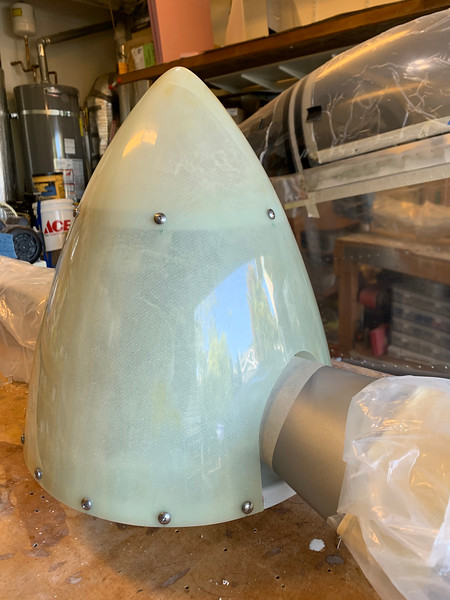
With a title like that, you would think that I had the perfect system and I'm here to provide a "how to" method to make sure that the spinner was perfectly centered and tracked with no wobble on the nose.

Alas, I'm just looking for hints on how to do it right.
 
Dead center

A good size milling machine makes a really accurate way to hold it exactly true if you have access to one.
 
I am not sure if my method was any better or more accurate than the next person but I used a dial indicator (https://en.wikipedia.org/wiki/Indicator_(distance_amplifying_instrument), attached to my cherry picker as a solid piece to attach it to. I took all my spark plugs out for ease of turning the prop and tried it at different points on the spinner.
I am told that my spinner looks dead on when turning, I have never seen it as I am the only one that so far starts and runs the engine.

However, if vibration is one of the guide in judging, mine has turned out nicely as we tried the dynamic prop balance and it was already very nicely balanced 0.13 and 017 (depending on the RPM)
 
My trick was to bolt a micrometer to my stepladder and cleco clamp the spinner in place. I kept adjusting it until the spinner ran true, then I drilled the holes.

(When I changed engines and props, I just let Catto fit the spinner.)


(Click to enlarge)
 
Last edited:
I use the "Dial Gauge" method on the initial build installation

One addition though

When I've got everything perfectly (or as perfectly as I can manage at least !) aligned I drill 3 x 3/32" holes at approx (buy not exactly) 120 degree intervals through the spinner moulding and into the back plate (paying attention to hole edge clearance in both parts of course).

The logic here is 2 fold

1) When I re fit the spinner after prop bolt torque checks etc I use 3 x 3/32" drills as "index" pins to hold the spinner in exactly the right place as all the screws are all tightened. Once all tight I simply remove the drills.

2) With the 3 holes not being at exactly 120 degree intervals the Spinner will not fit on the index holes unless it's in the "correct" position. Murphy states that if it would fit in 2 orientations (ie 2 blade prop) unless checked it would inevitably go on the wrong way .......
 
I used MDF to make a rotating platform and then used some dial calipers to set up my fitment:

1) Center the flange on the rotating base. The axel is a #30 drill into the bench. Runout was < 10 mils.
i-fKsKFxp-L.jpg


2) Use an upper dial caliper to center the spinner. Measure and sand the edge of the spinner to get it to center. < 15 mils all round on the upper caliper when done.
i-nTVRCcb-L.jpg


3)Used the Hartzell pattern plus a laser level to mark the edges of the cutout on the spinner.
i-27CgBDt-L.jpg


4) Looking good with the prop attached.
i-7CVspzn-L.jpg
 
My trick was to bolt a micrometer to my stepladder and cleco clamp the spinner in place. I kept adjusting it until the spinner ran true, then I drilled the holes.

Yes sir, that looks familiar!
 
Back
Top