What's new
Van's Air Force

Don't miss anything! Register now for full access to the definitive RV support community.

PMag issue

eddieseve

Well Known Member
Hi Guys,

I looking for some suggestions for a possible cause for the issue I experienced.

Today I was going to change the oil and filter, so what better way to warm up the oil, than to take my wife for a fly. The RV was preflighted, master and alternator on and as I was getting settled I accidentally kicked one of the PMag power switches off, no big deal just turned it back on and then went through my normal startup procedure. Prime the engine for 5 seconds, mixture to idle cutoff, crack the throttle and engage the starter, for 2.5 years the engine has always fired after 2 blades, today nothing. My initial thought, not enough fuel, so I gave it another 2 seconds and cranked again, nothing.

Waited for about 1 minute and tried again, nothing, waited another 30 sec and tried again, nothing. By now the battery is starting to go a little flat so I gave up, pulled it back into the hangar and pulled the cowls and put the battery on charge.

I noticed the sniffle valve was dripping fuel, so that was not the issue.

Turned the master on again to see if the LEDs on the PMags where lit, no lights.

Grabbed the multi meter and checked for 12v at the connector, no power, so I checked the fuse, and it's blown, it's 5A as recommended, so I am wondering if de-powering and turning back on again without the engine running could cause this to happen?

I replaced the fuse, re-cowled pushed the RV outside and the engine fire right up.

Does anyone have any explanations for this?

One other question, I am running both PMags through the same fuse, could this eventually cause this to happen?

Cheers
 
EMAG recommend a dedicated, pull-able 3A circuit breaker for each unit. They say if using a fuse it should be "slow blow". That implies there is some inrush current they are aware of. I would say it is possible you could blow a shared 5A fuse doing what you did and there may be nothing wrong with the units.

If it were me I would install two CB's so you can check and reset them, one to each bus if you have an E-bus. At a minimum don't share the fuse. If it blows you have no power to either ignition.
 
:DEddie??.what would Brownie say ;)

Richard is right, two separate sources.

Do you still have a magneto on your workbench?

Give me a call if you get a minute. And Richard?.get to work on that -10 and stop reading VAF
 
You need independent pullable breakers and engine case grounds for each P-mag. You do not want one component / wire to take both ignitions off line.
 
Some things on our aircraft are extremely important and critical systems. if you don't understand why a manufacturer has made their installation instructions for fuel, ignition, prop, engine etc the way they did, do not stray without full understanding and good reasons.

Bevan
 
FYI, I'm using fuses just fine, but I did have to special order a couple of "SLOW BLOW" fuses from an electronics shop. They look quite different than normal auto blades and were quite a bit more expensive.
 
Andy,

I've been told there is no such thing as "slow-blo" in an automotive blade style fuse. I'm talking about ATC fuses that fit into a traditional fuse block. If you have found a slow-blow for this type of block, I would like to know where you found them.

Bevan
 
Last edited:
FYI, I'm using fuses just fine, but I did have to special order a couple of "SLOW BLOW" fuses from an electronics shop. They look quite different than normal auto blades and were quite a bit more expensive.

Andy,
Where did you find the slow blow fuse? All I have seen are 5A x 250V and none for the 14v.
 
Thanks for sharing your story Eddie.
Question though,
If you use that switch/cb combo, how do you perform the internal generator test preflight? Ie p-lead ungrounded, but no external power?
Cheers
 
Those switches only provide power to my PMags, I have a standard ACS ignition switch that handles grounding, ungrounding my Mags, plus engine start.

Cheers
 
Those switches only provide power to my PMags, I have a standard ACS ignition switch that handles grounding, ungrounding my Mags, plus engine start.

Cheers

Ah right, that makes perfect sense. Ive got a CB, then a DPDT switch. OFF-RUN-TEST (OFF-ON-MOM).

cheers
 
For those of you that don?t know how the P-mags work, here is a primer:

If wired per the P-mag manual, the P-mags require a power and ground wire, as well as a P-lead. There is an optional tach signal pin and two others used for the ?jumper?. (See this thread for details on timing the P-mags.)

The power and ground should be supplied via 18 gauge (or heavier) wire. The Positive lead (pin 5) should have a 3 amp switchable circuit breaker, per the P-mag manual.

The p-lead grounds the P-mag, same as a traditional magneto.

With the switchable circuit breaker installed, you can pull it periodically to test the P-mag?s internal generator. (I test mine before every flight and at 500.5 hours I found one of my P-mag?s internal generator had failed. This should be a hint for those of you who are running an electronic ignition and one P-mag.) I would not recommend the use of a breaker-switch because they can be bumped off in flight. A pullable breaker is much less likely to pulled (turned off) in flight.

If you use fuses, then you have to add another way to test the internal generator function. A switch of some type will be required. The problem here is you have just added a lot of complexity to your ignition system, which is never good. It is best to wire them per the manual. This means grounding each of them to a separate engine case bolt and separate power feeds. As the maker of the EICommander who has helped a number of people (customers and non-customers), I cannot stress this enough!

FYI, I'm using fuses just fine...
How do you test the P-mag's internal generator?

...As far as I know, Pmags have a built-in crowbar over-voltage protection system...
Are you sure? I could find no reference to this in the manual.
 
How do you test the P-mag's internal generator?

Here is how I have setup mine,

The power source to PMAG goes thru a toggle (SPDT) switch with an inline fuse connected to this power line. The toggle switch closes the circuit either to the PMAG or an LED warning light, this is that if I accidently leave it in the off position to the PMAG, the warning light is lit.

At the run up area, I switch the PMAG power off and I do my normal PMAG test, also periodically check it with a real low RPM to test the generator portion of the PMAG. If the fuse is burnt, I will know it since the LED wouldn?t light up.

Many ways to skin the potato

I like you LED idea, I think I might steal that :)

Cheers
 
If you have an EMS with a couple of spare inputs, you can do what I did: run two of your spare inputs to the P-Mag's "ships power" input, so you can be assured you have power to the actual ignition, rather than "should have" based on a switch position.

I used DPDT switches for ignition, with the "off" position opening the Pmag ignition circuit, but also grounding an input on the Dynon, so I get a caution message and red light on the screen for that, but the Dynon also measures the voltage to the PMag and will alarm if it goes below a certain voltage.

What I've found through another VAF'er with this arrangement is that if you have ships power off but the engine is running above the self-sustaining speed for the P-mags is that the Dynon will then measure the PMag's internal alternator voltage.

This could give you early warning of a possible fault if you fly with ships power off to the PMag and the internal alternator fails you'll get the alarm, restore ships power and then know your ignition is US before the next flight, rather than finding out during the runup next time.
 
I have the tyco's for power and breakers and the standard ignition for starting and fouled plug testing.

Those switches only provide power to my PMags, I have a standard ACS ignition switch that handles grounding, ungrounding my Mags, plus engine start.

Cheers
 
If you have an EMS with a couple of spare inputs, you can do what I did: run two of your spare inputs to the P-Mag's "ships power" input, so you can be assured you have power to the actual ignition, rather than "should have" based on a switch position.

I used DPDT switches for ignition, with the "off" position opening the Pmag ignition circuit, but also grounding an input on the Dynon, so I get a caution message and red light on the screen for that, but the Dynon also measures the voltage to the PMag and will alarm if it goes below a certain voltage.

What I've found through another VAF'er with this arrangement is that if you have ships power off but the engine is running above the self-sustaining speed for the P-mags is that the Dynon will then measure the PMag's internal alternator voltage.

This could give you early warning of a possible fault if you fly with ships power off to the PMag and the internal alternator fails you'll get the alarm, restore ships power and then know your ignition is US before the next flight, rather than finding out during the runup next time.


Could you share what inputs you used for this?

What did you configure to have displayed on the Dynon screen?

Cheers
 
If you have an EMS with a couple of spare inputs, you can do what I did: run two of your spare inputs to the P-Mag's "ships power" input, so you can be assured you have power to the actual ignition, rather than "should have" based on a switch position.

I used DPDT switches for ignition, with the "off" position opening the Pmag ignition circuit, but also grounding an input on the Dynon, so I get a caution message and red light on the screen for that, but the Dynon also measures the voltage to the PMag and will alarm if it goes below a certain voltage.

What I've found through another VAF'er with this arrangement is that if you have ships power off but the engine is running above the self-sustaining speed for the P-mags is that the Dynon will then measure the PMag's internal alternator voltage.

This could give you early warning of a possible fault if you fly with ships power off to the PMag and the internal alternator fails you'll get the alarm, restore ships power and then know your ignition is US before the next flight, rather than finding out during the runup next time.

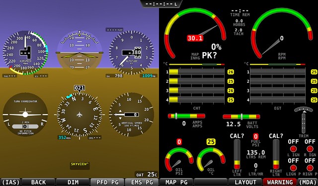
That is the setup I have with my 2 P-Mags and the DYNON SkyView EMS. It monitors the voltage at the actual P-Mag not at some switch. I used EMS pins D37-20 & D37-21, which I had available. I think I set it up as a contact to displays green if above 4.5v or red, with an audible alarm, if below 4.5v but would have to find the actual configuration if you need it. You can see the status indications for each P-Mag (LMAGST / RMAGST) in this photo:

N819PR1000hrs-Traffic_zpsb2477e87.jpg


You can replace the "status indication lights" with color coded voltage numbers if you want more detailed information. And yes, if you have ships power off but the engine is running above the self-sustaining speed for the P-Mags the DYNON measures the PMag's internal alternator voltage.

It is GREAT.

:cool:
 
Last edited:
Ok GalinHdz, now that is a nice setup. Where were you when I was wiring up my plane. Now if I just had the urge to dive back into the panel and pull some wires I'd be all over this. Maybe at the first condition inspection...
 
Andy,
Where did you find the slow blow fuse? All I have seen are 5A x 250V and none for the 14v.

Yep Same ones Bill listed.

http://www.mouser.com/ProductDetail/Littelfuse/16670004302/?qs=%2fha2pyFaduiakC2E%2fDTsDSo9RtSnnsbAs7C9d2d6tU%2fTEE87yhfudQ%3d%3d

and just so we are all clear. Every time this subject comes up the advise is to put breakers in. I'm not some renegade, the manual from E-Mag air does say you can use Slow-Blow fuses and that's what I did.

As to how I wired them, I used two 3-position switchs. Down is off (grounded) like a normal mag, middle is ship power on to the p-mags (ungrounded), momentary spring loaded up is NO ship's power to P-mag so you can test the internal generator. This works just fine and I have had no problems with them thus far. These switches get their power via the slow-blow fuses from the main buss behind the master. So it's master on, then flip both switches up to the middle and start. If you turn off the master the p-mags are on internal generator once they start anyways. I'm not suggesting you wire yours this way, just explaining what I did.
 
Could you share what inputs you used for this?

What did you configure to have displayed on the Dynon screen?

Cheers
For my PMag power I used Pins 4 & 23 IIRC. These two were spare but their wire stripe colour matched the tach input lines.

Configure them as contact inputs, with Range 1 being Red 0.0-4.5V and Range 2 being Green 4.5-5.0V. These input pins are 0-5V inputs, but are capable of sinking 15V without damage, though anything above 5V is simply read as 5.0V, hence the highish (4.5V) cutoff point.

IF you want to measure the actual voltage in real time, rather than ON/OFF as I do, you will need to use Pin 1 & 2, as I think they're the only ones that will do measurements above 5V - but that then limits your capacity to measure battery or avionics bus voltages...

For my two ignition switches, they are DPDT switches, one side actually switches the PMag circuit, the other grounds the Dynon's sensor line. I used Range 1, Red, 0.0-2.5V & Range 2, Green, 2.5-5.0V. I can't remember what pins I used there, but any GP input should do.

Ranges 3,4, & 5 are unused on both, as I can't see the point in measuring an in-between voltage in flight. IT's either enough, or it's not.

Then all you have to is configure where you want them on your screen, and if you want text associated with them, alarm as latching or self-clearing, etc...Mine are bottom-right in the 50% screen and show "OFF" if there's a problem and "OK" if, well, everything is OK! :p


15673431886_aeae2ed8bf_z.jpg
 
Thanks to both of you for your Dynon setup information, that has given me lots to ponder, like Andy I am wondering if I want to dive under the panel again, but what you guys have done is fabulous.

Cheers
 
Yep Same ones Bill listed.

http://www.mouser.com/ProductDetail/Littelfuse/16670004302/?qs=%2fha2pyFaduiakC2E%2fDTsDSo9RtSnnsbAs7C9d2d6tU%2fTEE87yhfudQ%3d%3d

and just so we are all clear. Every time this subject comes up the advise is to put breakers in. I'm not some renegade, the manual from E-Mag air does say you can use Slow-Blow fuses and that's what I did.

As to how I wired them, I used two 3-position switchs. Down is off (grounded) like a normal mag, middle is ship power on to the p-mags (ungrounded), momentary spring loaded up is NO ship's power to P-mag so you can test the internal generator. This works just fine and I have had no problems with them thus far. These switches get their power via the slow-blow fuses from the main buss behind the master. So it's master on, then flip both switches up to the middle and start. If you turn off the master the p-mags are on internal generator once they start anyways. I'm not suggesting you wire yours this way, just explaining what I did.

I did the same as Andy. I liked the idea that the whole circuit is protected
all the way back to the fuse block by the slow-blow fuses. It seemed to me with the breaker the wire from the breaker to the main bus is unprotected. At least that's the way my mind saw it(see avatar).
 
...

What I've found through another VAF'er with this arrangement is that if you have ships power off but the engine is running above the self-sustaining speed for the P-mags is that the Dynon will then measure the PMag's internal alternator voltage.

This could give you early warning of a possible fault if you fly with ships power off to the PMag and ...
I am not sure this is correct.

During the development of the EICommander we built a test rig that allows us to spin two P-mags simultaneously with an electric motor.

After reading this post we spun up our test P-mags and measured the voltage across the power and ground leads. The measurement on one was in millivolts. The other one has a bad diode and put out over 24 volts. (We have known of this problem for some time and since we don't fly with these P-mags and because we may have been the cause of this failure, we haven't sent it in for repair.)

After checking with Emag, they confirmed that the P-mags have a diode to prevent them from back powering your electronics.

If you choose to connect the power leads to your EFIS, be careful because with no load, high RPM, and a bad diode the P-mag can put out well over 60 volts. (We have toasted some EICommander development units before we realized one of our P-mags had a bad diode.)
 
Last edited:
Does it matter that these are listed as 80v fuses, and not 12 or 14v?

Good question. I didn't know so I Googled it and found this on a ham radio site.

Fuses actually have TWO ratings. Voltage AND current.

1. You may use a higher voltage rated fuse anywhere a lower voltage fuse is used, as long as the current rating is the same. THUS, the Handbook statement that you can use a 1 Amp. 250 Volt fuse in a low voltage (e.g. 12 Volt) circuit in place of a 1 Amp. 32 volt fuse. You MAY NOT safely use a 1 Amp. 32 Volt fuse in place of a 1 Amp. 250 Volt fuse!

2. The voltage rating DOES matter. The fuses are designed to ensure that when a fuse blows, the result will not lead to an arc inside the fuse body. (600 Volt rated fuses are usually ceramic insulated to withstand the additional heat and stress from the possible higher voltage.

3. The current rating of a fuse is for AC OR DC. It does NOT matter. The "appearance" of a blown fuse tells you nothing about the type of current (AC or DC) going through the fuse, just the AMOUNT OF CURRENT flowing through the fuse when it failed. A large surge will "vaporize" the fuse element, whether it's AC or DC. A small amount of overload will often leave much of the element still visible, whether the current was AC or DC.

4. The fusible element width, etc. is NOT determined by the voltage rating, but by the current rating. 10 Amp fuses will appear similar, whether they are 32 Volt or 250 Volt units. Low voltage (e.g., 32 volt types used in Automotive applications) will often have thicker or wider, or physically "larger" fusible elements because they typically carry larger CURRENT than 250 volt rated fuses. Auto (cylindrical type) fuses often go up to 20 or 25 Amps, values not often seen in the 250 Volt variety. (Think about it: 20 Amperes from the AC line in the U.S. would be protecting 2400 Watts- a rating that meets or exceeds the main circuit breaker of many residential lines. (Usually 15 or 20 Ampere service.) Yet, 20 Ampere fuses are common in automotive lighting systems, Air conditioning systems, etc.)
 
I am not sure this is correct.

During the development of the EICommander we built a test rig that allows us to spin two P-mags simultaneously with an electric motor.

After reading this post we spun up our test P-mags and measured the voltage across the power and ground leads. The measurement on one was in millivolts. The other one has a bad diode and put out over 24 volts. (We have known of this problem for some time and since we don't fly with these P-mags and because we may have been the cause of this failure, we haven't sent it in for repair.)

After checking with Emag, they confirmed that the P-mags have a diode to prevent them from back powering your electronics.

If you choose to connect the power leads to your EFIS, be careful because with no load, high RPM, and a bad diode the P-mag can put out well over 60 volts. (We have toasted some EICommander development units before we realized one of our P-mags had a bad diode.)

THANKS for this good info. I may be reading the millivolts which gives me a GREEN indication on my EFIS when the engine is running and I cut the ship power to the P-Mags. I will have to re-think the installation since I sure don't want the P-mags to accidentally destroy my EMS if a diode goes bad.

:cool:

No problem, we are happy to help.

While we like what you are trying to do by connecting them to your EFIS, we have also tried to figure out a way for the EICommander to tell you if the P-mags are running off internal or ship's power. So far, no joy. The Pmag's serial stream does report the voltage its internal buss sees but it doesn't tell you where it is coming from. They may change that at some point in the future, and if they do, we will update the EICommander's software.

For now the only reliable test is to drop power to them.
There's no issue with that though is there? Once you're airborne, pull ships power and let the EICommander report the loss of voltage if it happens. Restore ships power, land and know you need to fix it before the next flight.
 
If you don't mind, where did you get this information?

I am positive I had received that tidbit during a phone discussion with Emagair but wasn't sure, so I just called them to confirm. Today, they said NO crowbar. :confused: Something has been misunderstood/remembered here so I oppologize for the apparent mis-information. Unsupported data from my post you're quoting has been deleted.

Bevan
 
Last edited:
There's no issue with that though is there? Once you're airborne, pull ships power and let the EICommander report the loss of voltage if it happens. Restore ships power, land and know you need to fix it before the next flight.

As stated above, the EICommander cannot tell where the P-mag is getting power from, only that it is working.

Above around 800 RPM the 114 series P-mags automatically switch to internal power. So, turning off power in flight won't make any difference m grounding it is another story.

The older 113 series P-mags run off ship's power and only switch to internal power when they detect a loss of ship's power.

You can always do a quick, low power (1000 RPM), mag check before shutting down. (Or look at your EICommander, if installed.)
 
Last edited:
After much thought I think if the diode inside the Pmag goes T.U. I will be more concerned with the 60+ volts feeding back to the main buss frying some sensitive flight equipment or an umpteen thousand dollar radio. At that point a few hundred dollar EMS module would be the least of my worries.

My 2cents.

:cool:

While the voltage is high, the amperage is low. You can always add a diode to the power line, just incase.

In all the P-mag issues I've looked into, I'm yet to hear of an internal diode failure. Ours doesn't count because of the abuse / torture we have put them through.

One other thought, if a P-mag tried to back feed your electrical system, it would probably blow the breaker.
 
Last edited:
N941WR said:
I said:
What I've found through another VAF'er with this arrangement is that if you have ships power off but the engine is running above the self-sustaining speed for the P-mags is that the Dynon will then measure the PMag's internal alternator voltage.

This could give you early warning of a possible fault if you fly with ships power off to the PMag and ...
I am not sure this is correct.

During the development of the EICommander we built a test rig that allows us to spin two P-mags simultaneously with an electric motor.

After reading this post we spun up our test P-mags and measured the voltage across the power and ground leads. The measurement on one was in millivolts. The other one has a bad diode and put out over 24 volts. (We have known of this problem for some time and since we don't fly with these P-mags and because we may have been the cause of this failure, we haven't sent it in for repair.)

After checking with Emag, they confirmed that the P-mags have a diode to prevent them from back powering your electronics.
I can now personally confirm this is indeed the case, at least with my two P-Mags. I can deselect ships power to both P-Mags above 750 (Left) and 760 (Right) RPM and the Dynon reports that they are still powered on. The benefit of this is as I postulated earlier, as part of your after-takeoff checks, turn off ships power, and the Dynon will give me a Warning audio alert and message if one of the internal alternators fails.

How much current they are able to put out I'm not sure, but I suspect it to be very similar to the note in the VP-X operating manual, whereby a power pin that is actually "off" shows bus voltage with no load, however, if you try to actually draw any current from it, it shows 0 volts.
 
...The benefit of this is as I postulated earlier, as part of your after-takeoff checks, turn off ships power, and the Dynon will give me a Warning audio alert and message if one of the internal alternators fails.

...
Wouldn't you really want to know this before you took off?

I don't have a VPX, so I'm a little ignorant about their operation but can't you perform the same test on the ground?

When I had one of my internal generators fail, I discovered it on the ground by switching off ship's power during my run-up.
 
Wouldn't you really want to know this before you took off?
Certainly, and that is part of my runup checks.

However, by isolating ships power after takeoff, I now have ongoing monitoring - and datalogging - of the state of the internal alternators, and instantaneous audible and visual warning if one should fail in flight. Then it is simple to turn that side off, restore ships power, and regain that ignition, but the point here is, I now know I am operating off ships power on that side and can plan accordingly.

In the event of an accident, there is evidence not only that either or both ignitions were on/off, but that they were actually being powered.

In the screenshot below, the "x IGN" sensors are simply wired to ground through one side of a DPDT switch, the other side grounding the Pmag's "P-lead". The "x IGN P" proves there is voltage at the Pmag, either internal or external, independent of switch position.
15673431886_aeae2ed8bf_z.jpg
 
Very nice set up. Bummer it only works with the VPX. It drives me crazy that the P-mags don't put out a condition flag indicating where it is being powered from so we could report it on the EICommander.
 
Very nice set up. Bummer it only works with the VPX. It drives me crazy that the P-mags don't put out a condition flag indicating where it is being powered from so we could report it on the EICommander.
I think you've misunderstood my 'Stralian English! :p

My setup will work with any EFIS/EMS that supports a voltage input. For the Dynon, I ran two wires to the P-mag terminal screws from pins 4 & 23 on the EMS-220, then simply configured them as 0-2.5V = "OFF" and 2.5V + = "ON". The EMS can't tell, and doesn't care, where the voltage is coming from, but if I have my "P MAG POWER" switches off, and still have green dots, then I am assured all is right with the world. :D

Had I actually put a little more thought into it, I wouldn't have used 5V inputs, I'd have used the 12V inputs so I could actually measure the voltage, not just have it as ON/OFF. Even though I am jamming 12VDC into a 5V EMS pin, Dynon has assured that the pins are actually rated to sink 12V, it's just that anything over and above 5V shows as 5V.

The VP-X comment was merely my hypothesis as to why I can actually read the internal voltage when it is supposed to be isolated from back-powering the bus, thinking it may be similar in setup to the VP-X.

With the VP-x there is a note in the installation manual that warns you not to be concerned if you see bus voltage on a power pin that is supposed to be "off", as it is a quirk of solid-state electronics. There is no current behind it, and if you attach a load in place of a voltmeter, it will show 0 volts.
 
Back
Top