What's new
Van's Air Force

Don't miss anything! Register now for full access to the definitive RV support community.

anyone using Dynon Flush mount bracket?

IowaRV9Dreamer

Well Known Member
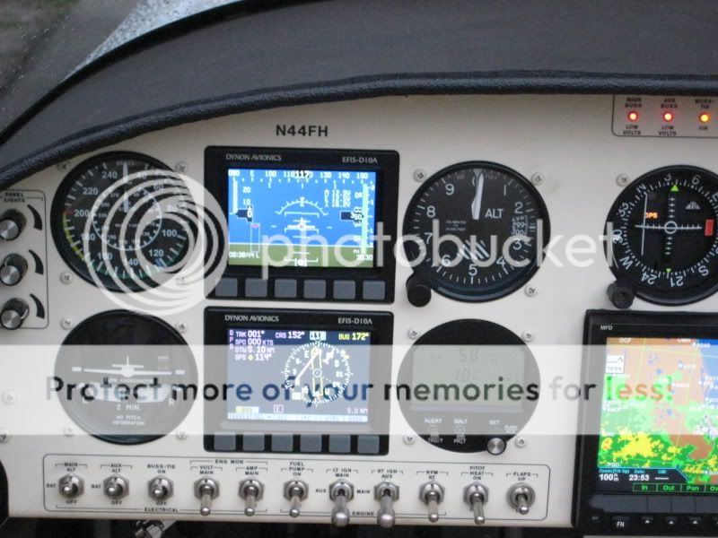
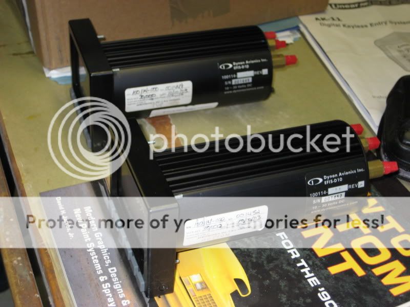
Hi - does anyone have any pictures of how a Dynon D10 / D6 looks when flush mounted using their braket? If you did this, would you do it again?

I did a search, but found some really old posts and no pics.

Also, does anyone have a spare bracket they'd like to get rid of :p

Thanks for any info?
 
FLUSH DYNON

I do have one, installed by Stein. When I had to take out the Dynon for access it was so hard I called Stein to make sure I wouldn't break something! He said they're very tight and to just horse it out - that worked but hard to do and to replace - just a lot of force. Will send pics when I get a chance. Panel pic can be found in RV08 panel thread, I think page 14. Bill
 
Think so

Believe I have a new flush mount bracket I did not use, will check when I am at the hangar on Monday.
 
Dave, here's a picture of the RV-7 panel with the flush-mount Dynon D-10As. Works great. You have to loosen four nuts each from behind the panel and the units pull out from the front. Absolutely do it again. Hope this helps.

003-1.jpg
 
I have the bracket envy

Bill & Pat - your panels looks great! Thanks for sharing the pictures.. the flush mount is definately what I want.

But I am confused. I'm looking at a drawing of the dynon bracket and it looks like it has four holes in it to mount to the panel. I don't see the screws in either of your installations, though.

Also, the drawing of the dynon bracket shows that it is a lot bigger than the dynon itself - too big to fit thru the hole. The panel hole is supposed to be 4.09 x 3.39 and the bracket is 4.505 x 4.555.

I think the way it is intended to work is that you bolt the bracket onto the Dynon, and then attach them to the panel from behind. Do I have this right? That seems opposite of what Pat posted... maybe there is another type of bracket?

BTW Pat - I really like the way your legends look. Any idea how they were done?

Mark - let me know if you have an extra bracket (PM)

Thanks to all! VAF rules,

dave
 
Last edited:
Pat - your picture looks awesome! It is the look I want. I'm looking at a drawing of the dynon bracket and it looks like it has four holes in it to mount to the panel. I don't see the screws in your installation, though. I wonder if they pressed studs into you panel and the bracket fits over them with nuts? I love the clean look without the screws and would like to know how to do it. BTW - I really like the way your legends look. Any idea how they were done?

Dave, thanks. Here is a picture that shows the studs coming out of the rear of the Dynons. These 4 studs slip through 4 holes in the bracket and you just snug it up with 4 AN locknuts. The panel was done by Aerotronics, so the labeling was done with decals painted over with clear, I believe.

IMG_0488.jpg
 
Dave,

I also used the flush mount bracket, and really like it. I believe your understanding of how the bracket attaches to the panel and how the EFIS attaches to the bracket is correct (basically how I did it). I riveted nutplates to the bracket, and then used screws (powder-coated to match the panel) to attach the bracket to the panel. To remove the D-10A, I pull the panel overlay, remove the four outer screws, and remove the bracket and EFIS together from the back. Then I can remove the bracket from the EFIS as needed, by removing the four inner screws as shown in Pat's pic.

dynons.jpg


One ooops I had in production was that the gent that cut and powder-coated my panel overlays cut the D-10A hole slightly too large (he looked at the wrong dimension on the drawing). He's going to replace that overlay section, but in the meantime, I spray painted the front of the bracket black before I attached it, so it blends in behind the panel, and is not visible (just makes the D-10A look a little bigger). Just mentioned it so you don't make the same ooops!

I also noted that Pat did not have screws showing, and it looks very nice Pat...really nice fit and finish! Did you have Aerotronics rivet the bracket to the panel, then fill and paint over the rivets? Looks really nice, and it looks like you can get the units closer together that way. When it comes time to replace that overlay, I may just copy your idea...looks good!

Cheers,
Bob
 
I get it now

Thanks Bob & Pat - I think I "get" it now... once the bracket is attached to the panel you can remove the unit (w/o bracket) from the front. I guess I just had it in my head that the panel hole was so tight (or even smaller) than the bezel and you couldn't squeeze it out.

I may try for the riveted bracket / no screws visibile approach too. The bracket takes up some valuable rear panel space but if I'm going to rivet it then I can modify it to fit.

Bob - I like you annunciators too. I'm using those same indicators. What did you make your bezel from and how did you do the bright/dim/test switch?

Thanks again,
 
Did you have Aerotronics rivet the bracket to the panel, then fill and paint over the rivets? Looks really nice, and it looks like you can get the units closer together that way. When it comes time to replace that overlay, I may just copy your idea...looks good!

Cheers,
Bob

That is correct, Bob. I just assumed that's the way it was done, I guess. The brackets are permanently affixed to the panel as you described. The only negative in doing it this way is that it makes the removal of the four locknuts a little tricky. You need a long extension and u-joint on your socket wrench to get to them. I stick a little grease inside the socket to get the nuts back on.
 
Makes sense Pat...great way to go. Taking out just the EFIS from the front takes out a step in removal too!

Dave, the annunciators are from MPJA.com, and are wired through a three position switch (ON-ON-MOM). The bright position is normal power (each light is on under the deisred condition), the dim position is the same, but routed through a zener diode to reduce the power, and thus the brightness, and the test position powers all lights on to the bright position. I'll get you a little schematic if you'd like one (the same gent owes me one on that switch wiring, as it was at the edges of my electrical wiring knowledge envelope! ;)).

The mount for the lights is one we made up to match the size of the Monroy Traffic Watch over the D-10A. Its two layers of AL riveted together. The back layer has round holes for the back of the lights to fit into and connect to, and has ears with nutplates to fit the screws through the panel. The front layer has square holes that the lights fit flush into, and is the same thickness as the panel overlay (.090) so it fits flush with the panel. I spray painted the front piece black to match the look of the Monroy and highlight the lights. Here's an early concept drawing of it:

annunlights.jpg


Cheers,
Bob
 
Last edited:
annunciator schematic

Thanks Bob - a schematic would be great, we could post it for all to see. I'm planning on some similar annunciators (already bought from the same source) and was trying to figure out how / if to dim them. I hadn't thought of a test switch but it is a great idea.
 
Annunciator Schematic

Workin' on it Dave. Will get it posted as soon as I can put it together.

Cheers,
Bob
 
Back
Top