What's new
Van's Air Force

Don't miss anything! Register now for full access to the definitive RV support community.

Gear tower mod alternative

bmellis11

Well Known Member
Sponsor
I want to do the gear tower mod, but I was wondering if it could be done in a different way than the two options regularly discussed. I'm not sure if this way has been discussed before and I don't know if it's feasible. So I would love some input from experienced builders.

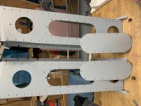
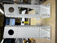
I think the tower would look better without the lightening holes. Also, removing the web between the two lightening holes or cutting F-802C-(L/R)-1 into three parts must have some structural impact, though it may be inconsequential.

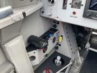
What I am wondering is if it would be possible to fabricate a replacement part without lightening holes that was attached entirely with flush screws to the side angles and hex bolts on the flange that attaches to the longerons. I can't tell from the plans, but it looks like you could reach up under the panel with a wrench to remove the bolts attaching it to the longeron. It sounds like a bit of a pain, but I guess you would only have the remove the longeron bolts once a year (maybe less if you flip the gear bolts?). I also can't tell from the plans if there would be enough space for the bolt heads on top of the longeron with the forward skin in place.

Has anyone tried this? Can anyone think why it wouldn't work or would be a bad idea?
 
Structurally what you suggest would be fine, as long as there are sufficient fasteners - which is the same with any of the mods.

Practically, Even if it is possible to get the whole panel out in one piece (which I can't confirm or deny), it is likely more difficult than taking a somewhat smaller panel out. So, on my upcoming repeat build, I plan to divide the panel into three, with the upper and lower fixed, and just a large middle panel removed in the way you describe. Note that the 'joint' where the middle panel connects to the upper and lower fixed portions still needs to have appropriate fasteners to carry the shear across that joint.

I've also been thinking about whether to eliminate the lightening holes for cosmetic reasons. It is a fairly thick plate, so as lightening holes go, it is a pretty good weight reduction.

So cut the lightning holes (for weight reduction) and cover with vinyl wrap for cosmetic reasons....:D
 
So cut the lightning holes (for weight reduction) and cover with vinyl wrap for cosmetic reasons....:D

Maybe the fake wood-grain stuff? ;)

But, seriously, I agree. I was thinking some 0.016 AL, but yes, a cosmetic cover over the holes would still give a lot of weight saving.
 
Another alternative is to not do a primary structure mod, but fix the accessibility problem it is meant to address:

1. Use Rocket-style tank vents in the wing roots, getting rid of the vent lines and making the cockpit safer by avoiding unnecessary potential for fuel/vapour ingress.

2. Install the landing gear bolts with heads in gear towers and nuts underneath, so they can be torqued from outside the aircraft.

3. To hold the bolt heads while torquing, either use retaining clips described at https://vansairforce.net/community/showpost.php?p=1527424&postcount=10 and
https://www.rv8-hangar.com/gear-bolt-mod/ or use a modified ring spanner.

4. Use flexible brake lines from TSFlightlines which can be arranged to improve access to the gear bolt heads.
 
I just finished my mod. Top lightening hole is out of view. Picture is from a friend’s. Mod picture is mine.
 

Attachments

  • FCF461AC-647E-4A11-8093-B54B65A7A87A.jpg
    FCF461AC-647E-4A11-8093-B54B65A7A87A.jpg
    245.1 KB · Views: 180
  • 8AD12B1E-8FC6-4ADF-AFF6-2C8D4787B9F7.jpg
    8AD12B1E-8FC6-4ADF-AFF6-2C8D4787B9F7.jpg
    354.5 KB · Views: 247
Last edited:
I ended up going with the three piece gear tower mod, but fabricated a solid cover from 0.040” 2024-T3 with #8 screws for the middle part for aesthetic reasons. I like the way it came out and think it will look even better when the face plate screws are painted with the towers. I think it would look even better with flush screws but I wonder if countersinking so many screws will weaken the towers. What do you guys think about countersinking here?
 

Attachments

  • gear towers.jpg
    gear towers.jpg
    324.2 KB · Views: 157
Last edited:
You made the right choice on where to divide the cover. I meant to come back and post after I checked, it would be very difficult to get a one-piece cover out, and would require removing the panel to do it.

Regarding countersinking - test data show that when loaded in shear, countersunk, or dimpled fasteners are slightly stronger than normal round head fasteners. This is because of the greater bearing area and/or the interlocking effect of the dimples.

But it does require that the material have adequate thickness to be countersunk without "knife-edge" on the holes. For a #8 screw, I think you would need at least 0.063" material to countersink properly.

Thanks for the response Steve. I think I want to use countersunk screws. The side angles are 0.063" and even though the covers I fabricated are 0.040", I could redo those with thicker sheet. I think I have two options:

1) dimple the existing 0.040" cover and countersink the side angles to fit the dimple -- I'm concerned about being able to get crisp dimples that leave the cover plate flat and about removing too much material from the side angles by drilling 20 countersinks large enough to fit the dimple of the cover plate.

2) use a thicker cover and countersink the cover screw holes -- Does the screw head add back all strength that is lost by removing material for the countersink?

If it were you, what would you do?
 
Structural pan heads. You'll never notice the cosmetics vs C/S after completion. Just put a screw every place there was a rivet.
 
Structural pan heads. You'll never notice the cosmetics vs C/S after completion. Just put a screw every place there was a rivet.

This is what I did.

+2. Thats what I would do too. Stick with 0.040" and use pan heads.

Thanks guys. I'm using AN515-8R8's right now and I'm not crazy about the look. If I can't change my mind on that point, do you think there's any structural concerns going with a thicker cover plate with countersunk screw holes and using a screw like an AN509?
 
Thanks guys. I'm using AN515-8R8's right now and I'm not crazy about the look. If I can't change my mind on that point, do you think there's any structural concerns going with a thicker cover plate with countersunk screw holes and using a screw like an AN509?

Double check if 0.063" is thick enough to countersink for #8 before you go to the trouble. If it is, then structurally it is fine. Just heavier with that thick plate.
 
A plate thick enough to accept a #8 screw countersink would also have an unusual appearance to it. IIRC, the head height for that screw is 0.072", so it would become a very thick plate, 0.080 or more.
 
Double check if 0.063" is thick enough to countersink for #8 before you go to the trouble. If it is, then structurally it is fine. Just heavier with that thick plate.

Do you recall where you can find the chart for minimum thickness for each screw type? I looked through my books and couldn't find anything other than a recommendation to go no deeper than 2/3rds of the sheet thickness and to leave a minimum of 0.02" beneath the countersink.
 
Do you recall where you can find the chart for minimum thickness for each screw type? I looked through my books and couldn't find anything other than a recommendation to go no deeper than 2/3rds of the sheet thickness and to leave a minimum of 0.02" beneath the countersink.

I just measured an AN509-832 and the head is about 0.077 tall.
 
Back
Top