
Van's Air Force
You are using an out of date browser. It may not display this or other websites correctly.
You should upgrade or use an alternative browser.
You should upgrade or use an alternative browser.
N159SB G3X Panel Upgrade Status
- Thread starter Brantel
- Start date


Brantel
Well Known Member
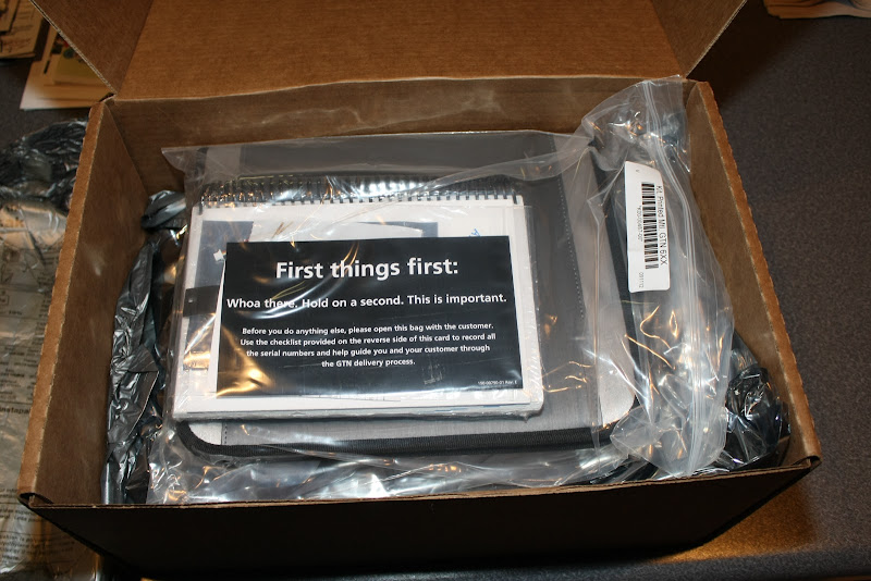
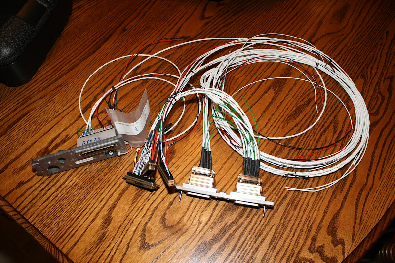
Started on the GTN650 harness tonight:
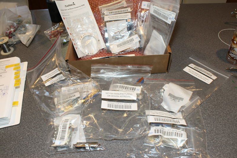
Here is whats in the box:
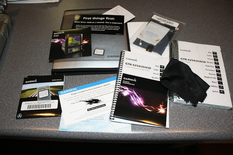
And all layed out...you get the data card and a spare data card, a Garmin portfolio to keep all your stuff in, user manual, quick ref manual, micro fiber cloth, database update certificate, gift for registering, sim software and a DVD:
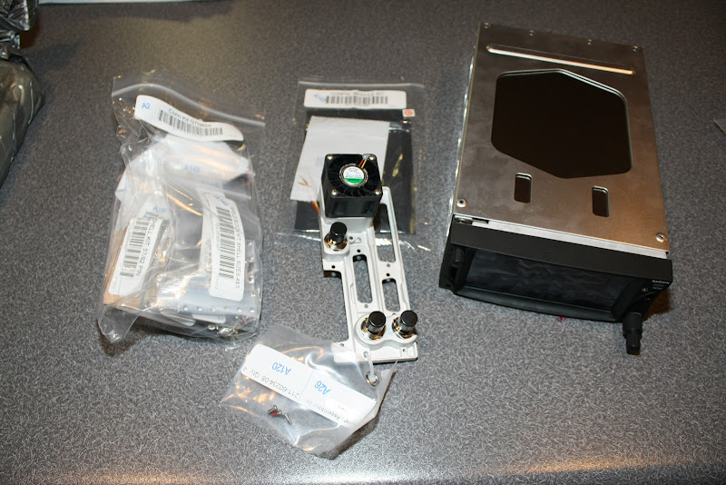
More:
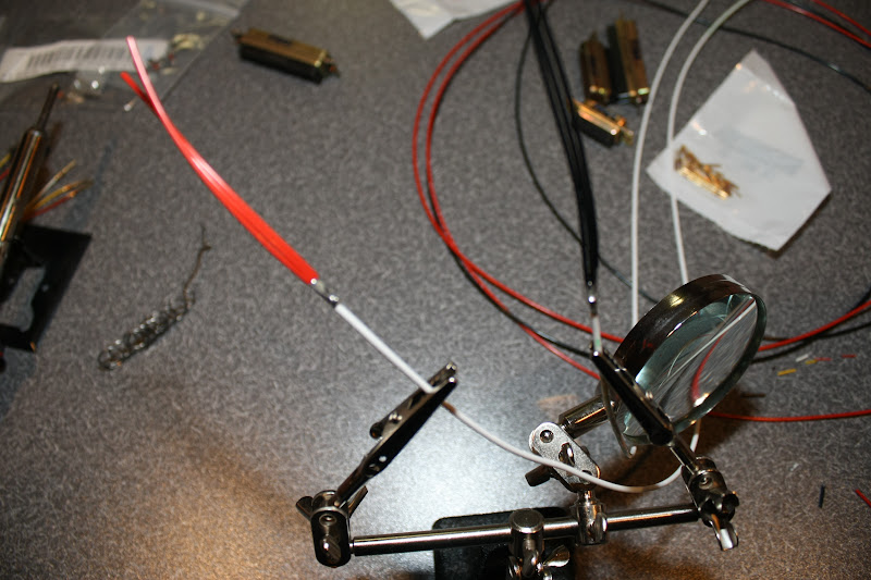
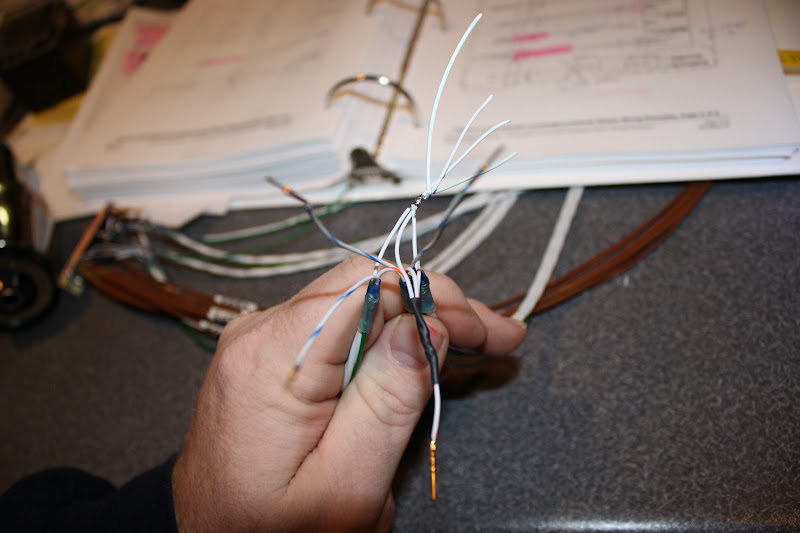
You have to split most of the power and ground wires up into multiple pins AND there are three different power inputs on this puppy! These 18ga wires get split into three 22ga ones:
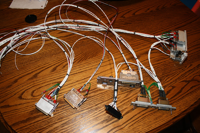
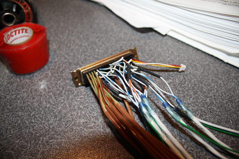
I almost got finished with the 650 harness but I screwed up and put the Nav audio in where the COM audio goes and did not have my pin extractor here at home. So this has to wait to get finished up. The ties are only temporary at this point. Some of the harnesses are starting to come together now so it will start to get complicated......here I have the GTX23ES, GMA240 and the GTN650 connected.
Here is whats in the box:
And all layed out...you get the data card and a spare data card, a Garmin portfolio to keep all your stuff in, user manual, quick ref manual, micro fiber cloth, database update certificate, gift for registering, sim software and a DVD:
More:
You have to split most of the power and ground wires up into multiple pins AND there are three different power inputs on this puppy! These 18ga wires get split into three 22ga ones:
I almost got finished with the 650 harness but I screwed up and put the Nav audio in where the COM audio goes and did not have my pin extractor here at home. So this has to wait to get finished up. The ties are only temporary at this point. Some of the harnesses are starting to come together now so it will start to get complicated......here I have the GTX23ES, GMA240 and the GTN650 connected.
humptybump
Well Known Member
When I'm building harnesses and working with connectors, I found it handy to have a large binder clip screwed to a block of wood and a couple alligator clips on bendable wire. Makes for a great third, forth, and fifth hands.
AirbusPilot
Well Known Member
Hi Brantel,
I am doing the same upgrading my RV-8 with G3X and GTN650, I have two question for you, how do you fix congifuration module for GTN650 and how you get GTN into demo mode.
Merry Christmas to you all,
Fernando
I am doing the same upgrading my RV-8 with G3X and GTN650, I have two question for you, how do you fix congifuration module for GTN650 and how you get GTN into demo mode.
Merry Christmas to you all,
Fernando
rleffler
Well Known Member
Hi Brantel,
I am doing the same upgrading my RV-8 with G3X and GTN650, I have two question for you, how do you fix congifuration module for GTN650 and how you get GTN into demo mode.
Merry Christmas to you all,
Fernando
Fernando,
I'm not sure what you mean by "fix" the configration module. It's installation is pretty straight forward. Wire it to pins 62, 62, 64, & 65 on P1001 and slide it into the slot on the connector. Garmin provides an insulator to wrap around the module before mounting.
I haven't done this yet, but per the manual, you just take Pin1, P1002 to ground to get into demo mode.
bob
AirbusPilot
Well Known Member
Fernando,
I'm not sure what you mean by "fix" the configration module. It's installation is pretty straight forward. Wire it to pins 62, 62, 64, & 65 on P1001 and slide it into the slot on the connector. Garmin provides an insulator to wrap around the module before mounting.
I haven't done this yet, but per the manual, you just take Pin1, P1002 to ground to get into demo mode.
bob
Bob,
Thanks for your answer, configuration module for G3X are fix with a screw to the connector shell, but as you said on GTN650 is just there rap in foam. About demo mode I was looking for that kind of demo mode by software in VFR GPS, this one is my first IFR GPS.
Merry Christmas
Bob,
About demo mode I was looking for that kind of demo mode by software in VFR GPS, this one is my first IFR GPS.
Fernando,
The GTN units have a demo mode you can enter by holding the Direct-To key down when applying power to the unit. This Demo mode will allow you to use all the features and functions of the GTN while either on a table or in the aircraft while on the ground. The GTN 650 pilots guide has instructions on page 18-14 (GTN 750 PG is page 19-14) explaining how to enter and manipulate the Demo mode. Also please follow this link to download a simulator from the Garmin web site. This will allow you to work with the functions of the GTN on you computer. http://www8.garmin.com/support/collection.jsp?product=010-00820-50&cID=194&pID=67886
Garmin Tim
Last edited:
Brantel
Well Known Member
Avionics stack harnesses complete....(except for a few screws)
Finished up the avionics stack harnesses today. Got the whole thing completed except for the screws that terminate the shield drains to to connector backshells. I need to get some shorter screws.
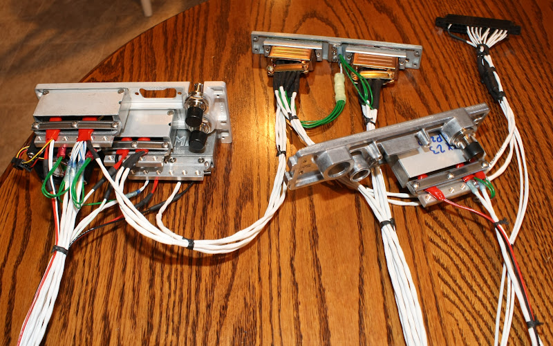
Left is the GTN650 harness, top middle is the GMA240 harness, bottom middle is the GTX23ES harness, right is the A210 harness.
All the avionics interconnects are finished. The rest are hanging free at the moment. Using waxed lacing cord to tie the bundles. Silicone self fusing tape to protect the wires under the new style clamps.
Something that just hit me was the contrast of how much shielded cable there is in a full Garmin install...pretty much anything with a signal gets shielded cable! My original legacy Dynon based system had very little. Then again I had some issues with noise in the audio system and the occasional DSAB bus errors etc.
Finished up the avionics stack harnesses today. Got the whole thing completed except for the screws that terminate the shield drains to to connector backshells. I need to get some shorter screws.
Left is the GTN650 harness, top middle is the GMA240 harness, bottom middle is the GTX23ES harness, right is the A210 harness.
All the avionics interconnects are finished. The rest are hanging free at the moment. Using waxed lacing cord to tie the bundles. Silicone self fusing tape to protect the wires under the new style clamps.
Something that just hit me was the contrast of how much shielded cable there is in a full Garmin install...pretty much anything with a signal gets shielded cable! My original legacy Dynon based system had very little. Then again I had some issues with noise in the audio system and the occasional DSAB bus errors etc.
Last edited:
Brantel
Well Known Member
Brian, that is looking very good indeed.
Is the Xpndr back plate just sitting there, or is it interconnected to the other wiring??
What about the EFIS wiring, or is that next on the list?
Carry on, you are going to be ready go go to work for Stein soon
Mike,
The GTX23ES xponder backplate is connected to the GTN650 backplate to so it can provide the certified position source for the ADS-B out ES function of the transponder. There is another three conductor shielded cable that is not connected yet to anything that will be connected to the G3X system's brain box the GSU73.
G3X system wiring is what I am working on now. Starting with the cables for the screens and then on to the EMS harness which will be a real treat!!!
After that will be the GX Pilot and Gemini PFD harnesses.
Then it will be time to install this octopus into the airplane!
I am sure this becomes a lot less fun if you have to do it all day long 5 days a week!
Brantel
Well Known Member
Started on the G3X harnesses. First will be the PFD2, then MFD, PFD1, GSU73 and then the EMS stuff...
Here is what you get for connectors and in the G3X install kit:
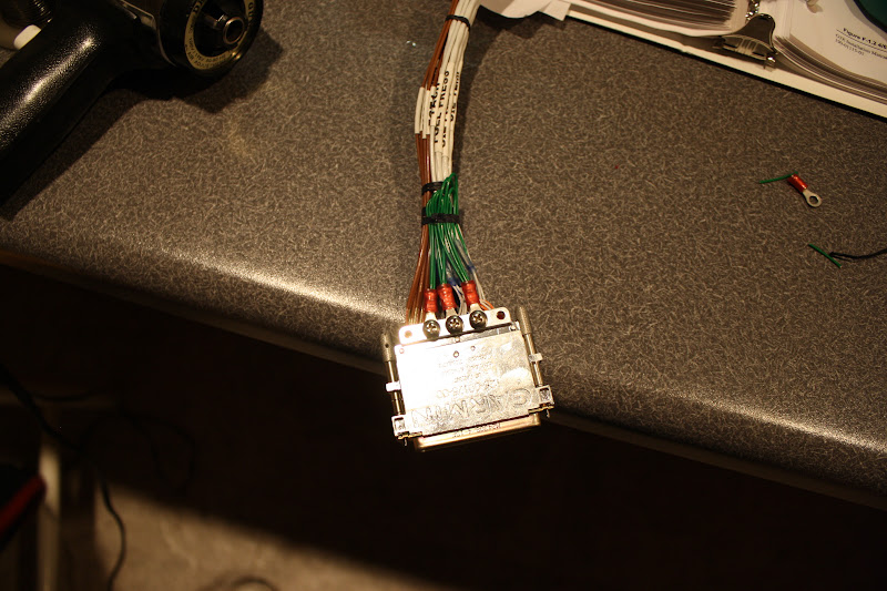
PFD#2 Harness complete! This was the easy one....
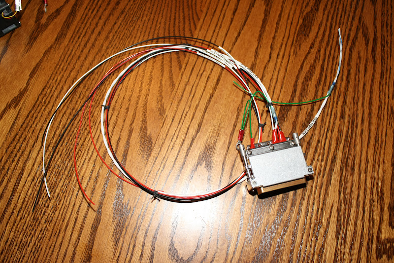
Power, Ground, Backup Power, Backup Ground, CAN bus, configuration jumper, lighting bus, signal ground, done!
Here is what you get for connectors and in the G3X install kit:
PFD#2 Harness complete! This was the easy one....
Power, Ground, Backup Power, Backup Ground, CAN bus, configuration jumper, lighting bus, signal ground, done!
Last edited:
Brantel
Well Known Member
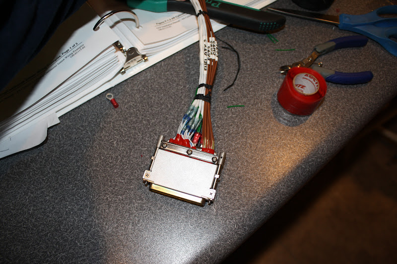
PFD#2 harness integrated and MFD harness fabricated and integrated....
Things are really getting interconnected now!
The MFD harness is way more complex than the PFD2 harness.
This one has two CAN bus lines spliced together, power 1, ground 1, power 2, ground 2, lighting bus, A210 serial, VP-X Pro serial, GDL39 serial, G3X alerts audio, G3X music audio and signal ground.
Next is PFD#1 which is a little less complicated but it has the config module in the connector....
Oh! And...we exchanged gifts with part of the family tonight and guess what I got????? A brand new TT GX Pilot Autopilot!!! Ho! Ho! Ho!
Last edited:
Brantel
Well Known Member
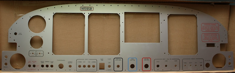
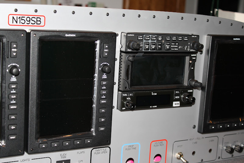
Today I received my replacement "Grey" powder coated panel. It looks as good as the first one, just a different color. Great job Front Panel Express!
Click for big version:
Today I finished up most of the avionics and G3X EFIS harnesses. The EMS harness is next.
What you see here is power, backup power, lighting bus, and integration connections for the GMA240 audio panel, GTN650 NAV/COM/GPS, A210 Com, GTX23ES remote xponder, PFD2, MFD, PFD1 & GSU73. Flying leads for the VP-X Pro, audio and mic jacks, GDL39, TT GX Pilot AP, and GPS feed to the TT Gemini PFD.
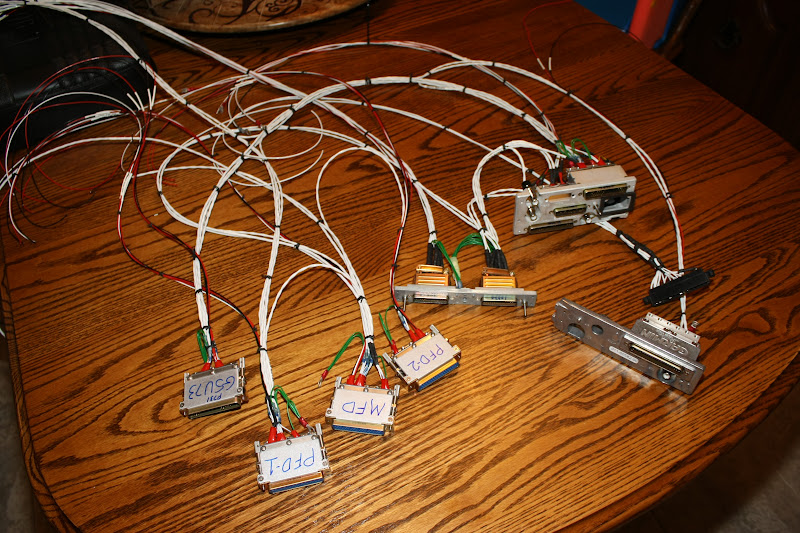
I am going to order some 8-32 x 1/4" screws for the shield drain terminals. Can't find any locally.
Click for big version:

Today I finished up most of the avionics and G3X EFIS harnesses. The EMS harness is next.
What you see here is power, backup power, lighting bus, and integration connections for the GMA240 audio panel, GTN650 NAV/COM/GPS, A210 Com, GTX23ES remote xponder, PFD2, MFD, PFD1 & GSU73. Flying leads for the VP-X Pro, audio and mic jacks, GDL39, TT GX Pilot AP, and GPS feed to the TT Gemini PFD.
I am going to order some 8-32 x 1/4" screws for the shield drain terminals. Can't find any locally.
Brantel
Well Known Member
Sat down this evening with the ohm meter/buzzer, some pins to stick in the female sockets and the manuals and rang out every single connection in this octopus to ensure it was correct. Good news...they all go where they are suppose to!
I figured it was time well spent because an error later will be much harder to find and fix as well as if something was crossed up, it could damage one of the units and we don't want that!
I figured it was time well spent because an error later will be much harder to find and fix as well as if something was crossed up, it could damage one of the units and we don't want that!
humptybump
Well Known Member
I know this is Brian's thread and do not want to hijack it. But ...
For those considering a major panel job - first time or upgrade - look at it like everything else in the build process. You can tackle it many different ways. Break it up into small tasks and find a sequence that works for you.
I got paralyzed on my "moder VFR panel" project. For me, rather than build the harnesses "device by device" I found I have better luck building "protocol by protocol". I did the CAN Bus first; then serial communications; then audio; and finishing with power.
My method may not work for everyone but I hope anyone wanting to do their own panel consider its not as complicated as it may first seem.
Of course, after buying all the materials, all the special tools, and all the spare parts, I'm pretty sure Stein could have done it for the same (or even less) money.
If you're in the ESVA area and doing a panel, I will probably have what you need
Now back to Brian's regularly scheduled awesomeness.
Brantel
Well Known Member
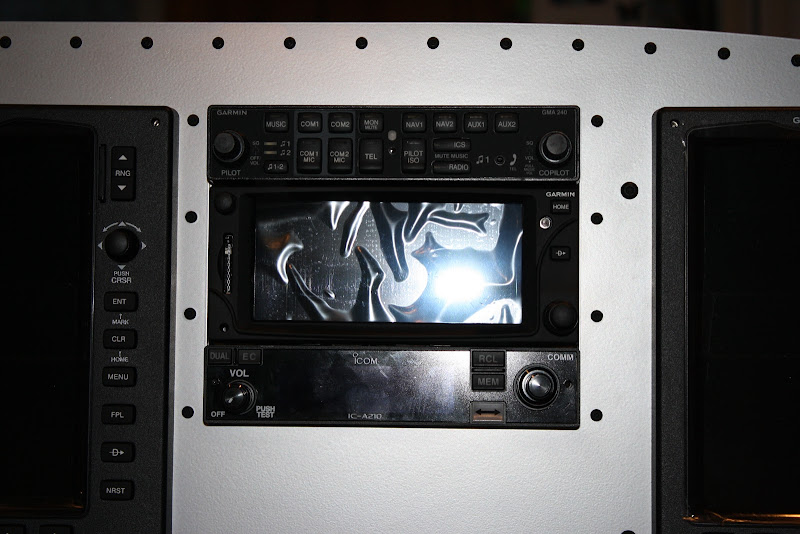
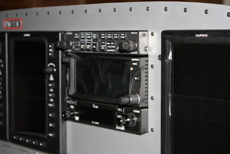
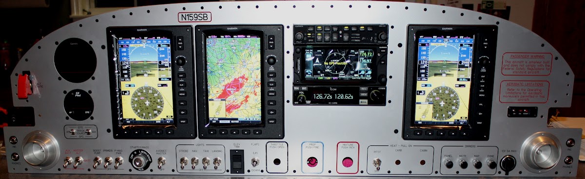
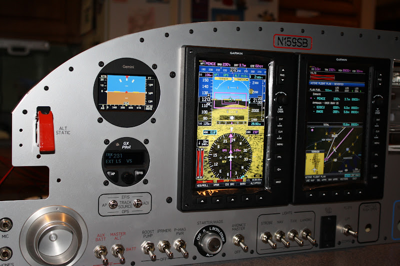
Since things have been slow thru the Christmas holidays, I thought I would wake up this thread with a pic....
Click for big version:
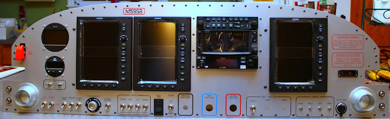
Forgot to bring the knobs for the dimmers home from the hangar. The screws holding in the round PFD and AP are temporary. I have 6-32 screws like the rest of the Black ones on the way from McMaster Carr.
So far the panel blank seems to be working out well.
Been having to work long hours this week due to our maintenance shutdown at work. Not much panel work going on!
Last edited:
rleffler
Well Known Member
I know this is Brian's thread and do not want to hijack it. But ...
For those considering a major panel job - first time or upgrade - look at it like everything else in the build process. You can tackle it many different ways. Break it up into small tasks and find a sequence that works for you.
I got paralyzed on my "moder VFR panel" project. For me, rather than build the harnesses "device by device" I found I have better luck building "protocol by protocol". I did the CAN Bus first; then serial communications; then audio; and finishing with power.
My method may not work for everyone but I hope anyone wanting to do their own panel consider its not as complicated as it may first seem.
Of course, after buying all the materials, all the special tools, and all the spare parts, I'm pretty sure Stein could have done it for the same (or even less) money.
If you're in the ESVA area and doing a panel, I will probably have what you need
Now back to Brian's regularly scheduled awesomeness.
Glen,
You may want to start a separate thread on this topic. I think it could be valuable to folks that are a bit timid with the wiring.
Your approach is exactly what I did with my 10. I have a data, audio, and power schematics that I created prior to wiring. Then it's simple just to follow your schematic and check off each wire as your complete it.
Yes, I did purchase about a grand worth of tools to do it myself. But now I have the tools to do a proper repair if necessary and a very intimate knowledge of how my avionics work. Priceless.......
Bob
Brantel
Well Known Member
Another thread got me to thinking about how many GPS's my airplane will have in it soon....
1 in the PFD
1 in the MFD
1 in the PFD2
1 in the GTN650
1 in the GDL39
1 for the APRS xmitter
1 in the Aera 796
1 in my IPhone
1 in my IPad
That's 9 total! Hope I don't get lost!
1 in the PFD
1 in the MFD
1 in the PFD2
1 in the GTN650
1 in the GDL39
1 for the APRS xmitter
1 in the Aera 796
1 in my IPhone
1 in my IPad
That's 9 total! Hope I don't get lost!
humptybump
Well Known Member
Yikes!
... but now that you mention it, my "simple modern VFR" setup will have five ! Ouch.
This thread is a real inspiration. Thanks Brian for documenting the milestones as you go. It got me over my slump
... but now that you mention it, my "simple modern VFR" setup will have five ! Ouch.
This thread is a real inspiration. Thanks Brian for documenting the milestones as you go. It got me over my slump
IowaRV9Dreamer
Well Known Member
How many have external antennas? Six?That's 9 total! Hope I don't get lost!
Brantel
Well Known Member
How many have external antennas? Six?
I am going to try and prevent any from being on the exterior of the aircraft.
1 in the PFD either on the glarshield or under the cowl
1 in the MFD either on the glarshield or under the cowl
1 in the PFD2 may not even put an antenna on this one, only one is required for the G3X and I plan two for redundancy.
1 in the GTN650 under the cowl, already mounted
1 in the GDL39 either on the glarshield or under the cowl
1 for the APRS xmitter in the right wingtip
1 in the Aera 796 either on the glarshield or under the cowl
1 in my IPhone not required
1 in my IPad not required
Brantel
Well Known Member
Brantel,
Great looking glass panel. Very nicely laid out.
Thanks Dan!
rleffler
Well Known Member
I am going to try and prevent any from being on the exterior of the aircraft.
1 in the PFD either on the glarshield or under the cowl
1 in the MFD either on the glarshield or under the cowl
1 in the PFD2 may not even put an antenna on this one, only one is required for the G3X and I plan two for redundancy.
1 in the GTN650 under the cowl, already mounted
1 in the GDL39 either on the glarshield or under the cowl
1 for the APRS xmitter in the right wingtip
1 in the Aera 796 either on the glarshield or under the cowl
1 in my IPhone not required
1 in my IPad not required
And I thought I was a little strange. I have six and thought that was overkill. I'm just waiting for somebody to ask where is the compass. I also have two magnetometers.
The antenna locations was the only awkward part. I've got two on top, two on the glare shield, and the last two are in the cockpit someplace (iPhone, iPad).
Bob
Brantel
Well Known Member
I can guess but what are we talking for total cost of this setup, minus the labor ? 20-30k ? It's awesome.
If you had to start from scratch (I already had several items) and used regular retail prices, you would be looking at somewhere between 30-35K. This is typical of a full Dual Screen IFR setup based on just about any of the manufacturers these days (total installed SYSTEM cost, don't believe the marketing hype). Remember that the IFR GPS/NAV/COM is about 1/3 the cost. I was able to do some trading and will be selling the original panel components to help offset some of the cost.
A VFR two screen version of this could be built for much less....
A buddy of mine said I was not going to be happy until my RV's cockpit looked like this:

What's wrong with that? Even after a year and a half, I bet I can still find (most) all of the controls blindfolded....can't be THAT complicated!
Let's see, an old Shuttle ditty......"to TFL to the PCMMU, an Item 2 before you're through..."
Brantel
Well Known Member
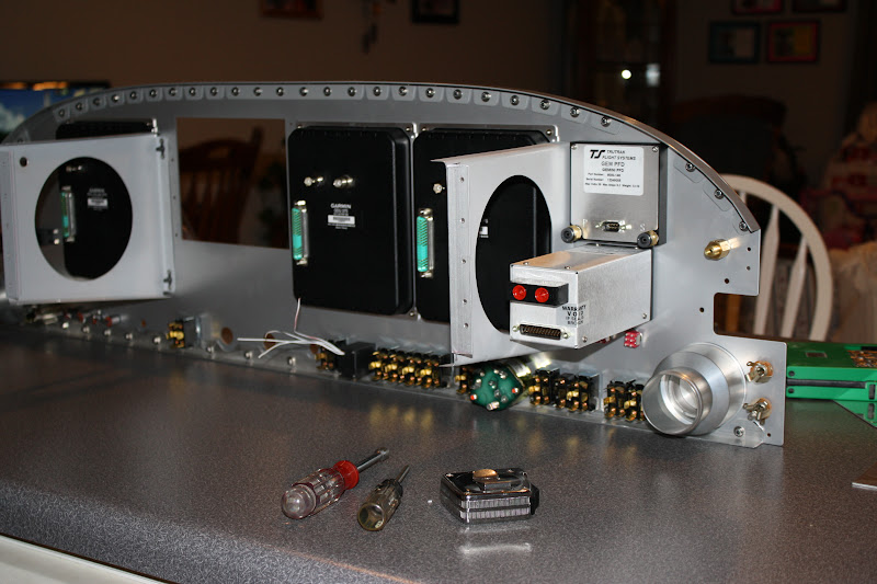
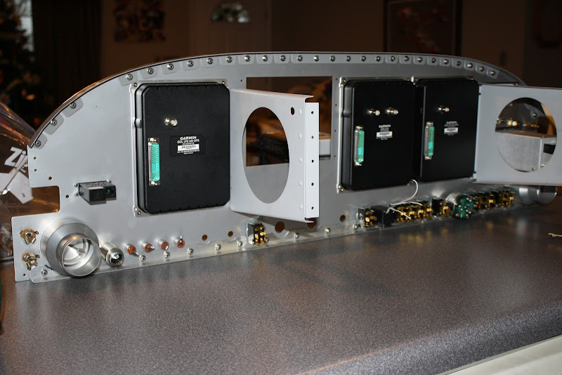
Time to backup and post some pics of how I mounted the parts and the radio stack...
Normal 1/2" x 3/4" angle. I will add a strap to the rear of the trays later tying em together back there:
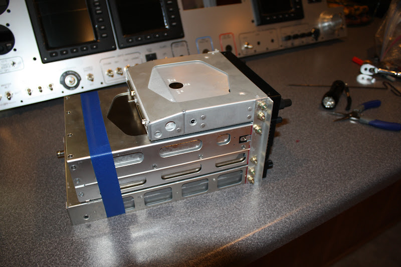
I used screws to hold the mount rails because I hate having to drill em out later if I ever want to upgrade or change to something new.
I also left 1/16" extra space between faceplates because I have ran into issues with tight faceplates before. I hate having to remove one device just to be able to get another out.....
For whatever reason, the faceplate of the GTN650 is a little narrower than the other devices.
I made the radio stack cut out large enough that the entire faceplate of all the devices can sit a little recessed into the panel. I think this looks better and it also allows the tray to be able to be removed without major surgery. I have had to get em out thru the subpanel before and that was a major pain!
Random shots of the back side:
A special post coming up here at midnight EST!!!
Normal 1/2" x 3/4" angle. I will add a strap to the rear of the trays later tying em together back there:
I used screws to hold the mount rails because I hate having to drill em out later if I ever want to upgrade or change to something new.
I also left 1/16" extra space between faceplates because I have ran into issues with tight faceplates before. I hate having to remove one device just to be able to get another out.....
For whatever reason, the faceplate of the GTN650 is a little narrower than the other devices.
I made the radio stack cut out large enough that the entire faceplate of all the devices can sit a little recessed into the panel. I think this looks better and it also allows the tray to be able to be removed without major surgery. I have had to get em out thru the subpanel before and that was a major pain!
Random shots of the back side:
A special post coming up here at midnight EST!!!
Last edited:
SmilingJack
Well Known Member
NICE!
Now that's better then watching the ball drop!
Congrats!
Now that's better then watching the ball drop!
Congrats!
Don Patrick
Well Known Member
Wow!
Now that's a nice panel!
Now that's a nice panel!
Auburntsts
Well Known Member
Brian,
Any tips for inserting the 22ga wires into those high density pins?
Any tips for inserting the 22ga wires into those high density pins?
Brantel
Well Known Member
Brian,
Any tips for inserting the 22ga wires into those high density pins?
Yep...see this post!
Its the only way to go no matter how bad it looks....
The 22ga are the easy ones. Trying to get 20ga just does not work without cutting a few strands out.
Typically however when 20ga is called for, it is split into multiple pins and when they do that, I use 20ga for the common wire and 22ga for the two split leads.
A good set of strippers is critical to getting a good enough strip without splaying the wire strands all over the place. I bought a set of the die/machinced type StripMaster strippers from AeroElectric Bob when he was selling slightly used sets. These typically run over a $150 dollars a set, he was selling them slightly used for much less. The cheap $35-$40 units do not do the job like the die type do.
Brantel
Well Known Member
Built the main EMS harness tonight. When you use the VP-X Pro, you get by with a few less wires in this harness since the VP-X Pro provides Volts, Amps, Flap and Trim Pos etc. to the G3X.
Started out cutting to length and tagging, stripping and pinning these thermocouple wires. This stuff is high $ because Garmin specs out something special so don't make many mistakes here...
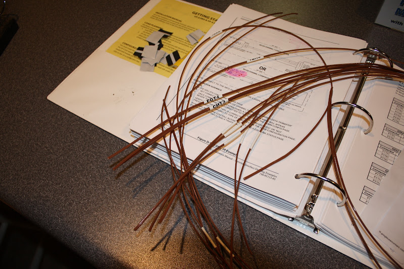
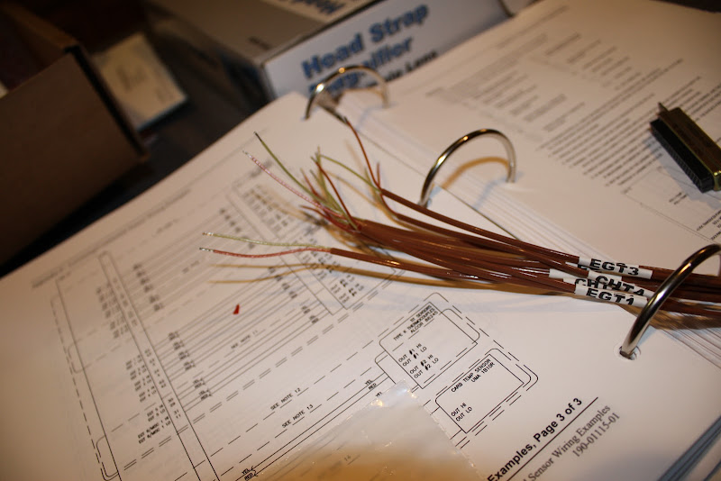
Then comes the fuel level sender wiring. I will either reuse the Dynon ones or most likely will switch to the Princeton ones since they work much better. Either case, I use the +12v sensor power and the 0-5V inputs.
Multiple cables get tied together for the power + LO/ground signals.
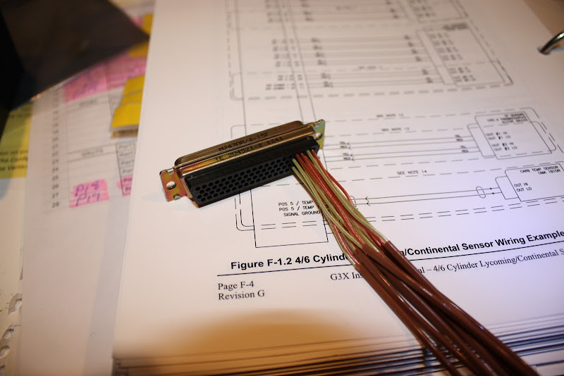
There is a config module in this harness along with a thermocouple for reference. These config modules take some rediculously small wire. It is almost impossible to work with this stuff without breaking the wire out of the pin after crimping. This wire is just too small!
Also added the carb and oil temp cables to the connector.
Next I added the cables for the new style solid state pressure sensors that Garmin provides. These are super high quality units. Must have been a good idea because Dynon copied Garmin's lead....fuel, manifold and oil pressure.
Again many pins and wires get tied common on these cables...takes some creative soldering and planing.
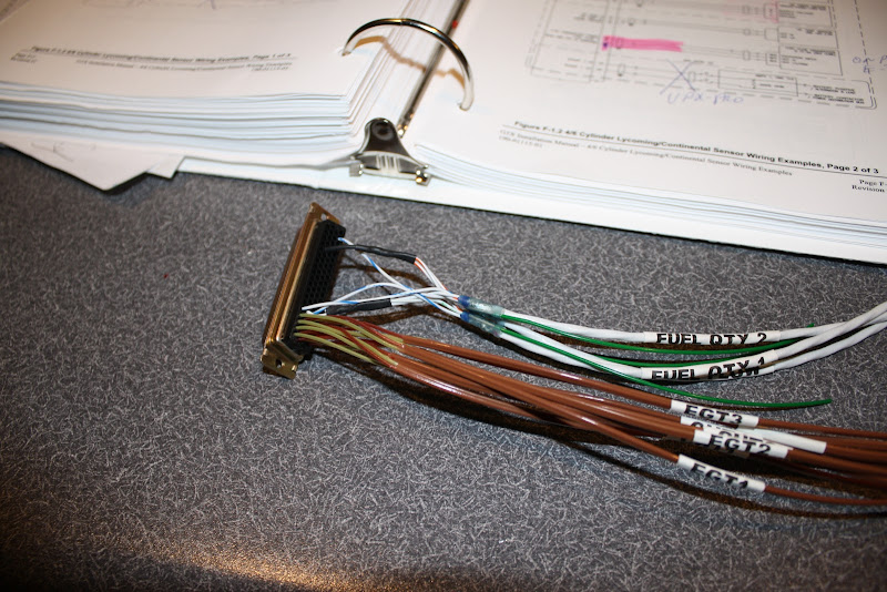
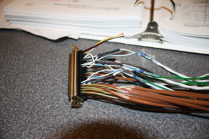
This puppy is almost full. It would be if it were not for the VP-X Pro...
I love solder sleeves!
Fruits of my labor:
Took all evening to make this one harness!
Next is the simple TT Gemini power and track source wiring along with the slightly more complicated harness for the TT GX Pilot. Then it is off to the cold hangar to install this thing!!!!
Started out cutting to length and tagging, stripping and pinning these thermocouple wires. This stuff is high $ because Garmin specs out something special so don't make many mistakes here...
Then comes the fuel level sender wiring. I will either reuse the Dynon ones or most likely will switch to the Princeton ones since they work much better. Either case, I use the +12v sensor power and the 0-5V inputs.
Multiple cables get tied together for the power + LO/ground signals.
There is a config module in this harness along with a thermocouple for reference. These config modules take some rediculously small wire. It is almost impossible to work with this stuff without breaking the wire out of the pin after crimping. This wire is just too small!
Also added the carb and oil temp cables to the connector.
Next I added the cables for the new style solid state pressure sensors that Garmin provides. These are super high quality units. Must have been a good idea because Dynon copied Garmin's lead....fuel, manifold and oil pressure.
Again many pins and wires get tied common on these cables...takes some creative soldering and planing.
This puppy is almost full. It would be if it were not for the VP-X Pro...
I love solder sleeves!
Fruits of my labor:
Took all evening to make this one harness!
Next is the simple TT Gemini power and track source wiring along with the slightly more complicated harness for the TT GX Pilot. Then it is off to the cold hangar to install this thing!!!!
Last edited:
Brantel
Well Known Member
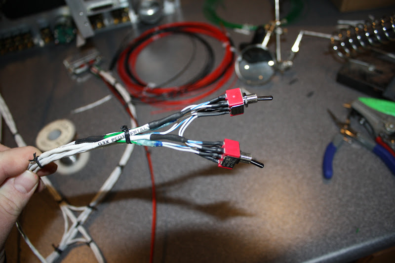
Worked on the TT GX Pilot and TT Gemini PFD harnesses today.
These Track Source switches add complexity to the situation and I am not sure they are worth it or not. While they do add some redundancy, 99% of the time they will be in the EFIS position.
Christer at SteinAir told me that they don't put these in as many panels these days...
These Track Source switches add complexity to the situation and I am not sure they are worth it or not. While they do add some redundancy, 99% of the time they will be in the EFIS position.
Christer at SteinAir told me that they don't put these in as many panels these days...
Last edited:
Brantel
Well Known Member
Finished the TT Gemini PFD and TT GX Pilot harnesses yesterday.
No big deal. The TT Gemini PFD harness needed back to back Schottky diodes on the power line since it only has one power input and must be backed up with my backup power system. Other than that these were normal. Not sure why all manufacturers don't add a built in second power input with internal diodes especially on a device intended to be used as a critical backup. I would pay the extra $5 to have this so I don't have to do it myself and have a lump in the harness where the diodes are. (That my critical feedback Andrew and Lucas, otherwise I love my Gemini!)
While wiring up the harness for the TT GX Pilot, I realized that I forgot the ARINC Out 2 line that must go from the GSU73 to the TT GX Pilot. No big issue, just made one up and added it to the bundle. The new style backshells are easy to work with when making changes to a harness! In contrast are the solder style connectors that TT provides with their products. I have grown accustom to most everyone else providing the Mil Spec style machined pin connectors that get crimped instead of soldered. To be quite honest I thought about replacing this solder connector that came with the TT GX Pilot with a crimp pin style but decided to go ahead and use it. I am good at soldering so it was not a difficult task to make this harness up but I can tell you the crimp pin style are much easier. I know they cost more but for me they are worth it. (That is my critical feedback Andrew and Lucas, otherwise I love my GX Pilot so far and based on other experience, I know it will work great in the air!)
Powered the additions up with the G3X in demo mode to verify all the interconnects and had an error where I had not flipped the RS232 lines going to the AP....fixed that (would have been much easier if I had used a crimp pin style connector) and it all worked great. In demo mode after you add the TT GX Pilot to the mix, the system acts like it is really working and flying the plane. All the integration works back and forth.
Thats about all I can do while here at home so now it is back to the airport to get this thing installed!
Last edited:
BillL
Well Known Member
RE: Post 137 AP Input Switch
Stein built my panel and I have a input switch on my AP also. I/we could not find a way to ensure known input from G3X and/or the 650, thus the switch.
If there is another way, it would be good to know a solid answer and eliminate the switch.
Stein built my panel and I have a input switch on my AP also. I/we could not find a way to ensure known input from G3X and/or the 650, thus the switch.
If there is another way, it would be good to know a solid answer and eliminate the switch.
In my case, the panel is wired without a switch. For me that is just one less switch that could be in the wrong position. The 650 is wired to the G3X, and the G3X is wired to the autopilot. So the AP is always controlled by the G3X.
If for some reason in what I anticipate to be a rare circumstance, the autopilot steering commands don't work, I can steer the autopilot from the control head or just hand fly it.
For me anyway, it is simpler to just work with a known configuration and simpler to know what to do if that configuration fails..
Last edited:
Brantel
Well Known Member
Stein built my panel and I have a input switch on my AP also. I/we could not find a way to ensure known input from G3X and/or the 650, thus the switch.
If there is another way, it would be good to know a solid answer and eliminate the switch.
I am with you Bill. Unfortunately there is no other way since the GX Pilot has no way to switch between or inputs for multiple sources.
In my case, the panel is wired without a switch. For me that is just one less switch that could be in the wrong position. The 650 is wired to the G3X, and the G3X is wired to the autopilot. So the AP is always controlled by the G3X.
If for some reason in what I anticipate to be a rate circumstance, the autopilot steering commands don't work, I can steer the autopilot from the control head or just hand fly it.
For me anyway, it is simpler to just work with a known configuration and simpler to know what to do if that configuration fails..
Definitely something to consider Mark. I struggled with this but in the end fell back on the past practice.
In the past most everyone put in a switch to switch the ARINC 429 signal feeding the GPSS/GPSV enabled AP between the EFIS and the IFR Navigator so the GPS could drive the AP by itself if needed. Now with the GX Pilot, it is very similar to the Digiflight II AP but it is different. Lucas tells me that it will not go into EFIS mode (mode where it follows an external command) unless both the GPSS and GPSV signals are present and active. The G3X always has these signals active but the IFR Navigators only do when on an approach with vertical guidance active. All that means is that to put in an ARINC transfer switch is pretty much useless since the times it would actually work are limited.
I did however put in a switch to transfer the RS232 signals between the two so that the AP could always have a ground track available even if the G3X bites the dust. The AP works much better if it has ground track available even when driving it around with the local knob....
Did the same for the Gemini PFD. It also will work without a ground track but it works better with one.
I would say that 99% of the time these switches will stay in the EFIS position. The G3X will annunciate that the AP is offline if the switch is in the wrong position so that error is covered. The Gemini PFD really does not care which one it gets it from as long as it has one and it is valid.
Last edited:
Brantel
Well Known Member
One of the things I have really begun to appreciate on the G3X system is the DEMO mode that the system can be put in. I was aware that there was some kind of DEMO mode available to dealers and units intended for demonstration but I did not know this feature was available to the general end user.
That being said, the DEMO mode of the G3X system is awesome. It basically lets you learn most of the operation of the system while sitting on the ground including the operation of the integrated GX Pilot autopilot.
I have been able to learn many things about the G3X system while it is sitting on my kitchen table instead of in the air burning avgas.
There is also an easy to get to Demo mode built into the GTN650 that makes learning this totally new technology easy as well. They also provide a computer simulator for the GTN series that one can play with anytime they want. There are many similarities with the GTN series and the 796 portable that makes the GTN an easy transition for me.
In my opinion, these Demo Modes help a bunch to increase the pilots knowledge of the operation of their gear as well as prevents them from spending too much time head down in the air. These things increase the safety margin if the pilot uses them...
Last edited:
Brantel
Well Known Member
Last night I made the brackets and mounted the remote xponder and the VP-X Pro between the firewall and the subpanel between the two main ribs. The xponder below so it can slide out and the VP-X on top.
Sorry no pics yet...
The GTX23ES and the GTN650 are going back to Stein for the firmware updates to make em both fully compliant with the ADS-B out requirements of 2020.
This weekend I hope to get the GDL39, aux battery and GMU73 mounted.
Sorry no pics yet...
The GTX23ES and the GTN650 are going back to Stein for the firmware updates to make em both fully compliant with the ADS-B out requirements of 2020.
This weekend I hope to get the GDL39, aux battery and GMU73 mounted.
Last edited:
Subwaybob
Well Known Member
Brian I have been meaning to ask you, what did you use to power up your panel? Mine is installed and yet to be powered. Thinking of putting a trickle charger on the battery and starting my video game. Remember mine is only 2 screens, not all of us are rich! What are your thoughts?
What are your thoughts?Brantel
Well Known Member
Brian I have been meaning to ask you, what did you use to power up your panel? Mine is installed and yet to be powered. Thinking of putting a trickle charger on the battery and starting my video game. Remember mine is only 2 screens, not all of us are rich!
I use a fully charged battery that I plan to use for the AUX Battery for short term use and a bigger battery off of my 4 wheeler for longer term use.
Whatever you do, don't connect it directly to a battery charger without also connecting them both to a battery. Some chargers have all sorts of weird output when not connected to a battery. The battery sort of acts like a filter and smooths all of that out.
Brantel
Well Known Member
Working on making an aux battery mount. Wife has been away on a women's retreat this weekend and I have been solo with the three girls and the youngest has been getting over the flu so the progress has been slow. It is 70° here today and I completely missed the opportunity to get anything done in the warmth....
I will post some pics of what I have been working on eventually...
I will post some pics of what I have been working on eventually...
Brantel
Well Known Member
The GTN650 and GTX23ES are headed back to SteinAir today to get their firmware updated to the latest versions.
These new firmware updates will make the GTN650/GTX23ES fully compliant with the 2020 mandate around ADS-B out.
Painful but necessary. Good thing is that these types of boxes don't get updated very often....good to get this done while I am not flying. Glad the new firmware came out during this period.
Still working on constructing the mounting for all the stuff that needs a home...
Last edited:
humptybump
Well Known Member
I was dealing with my backup battery location, mount, and leads this weekend. I still am not sure how I will address the rear support for the radio stack so I will be watching for your pictures

