What's new
Van's Air Force

Don't miss anything! Register now for full access to the definitive RV support community.

Solid state current sensing

wcalvert

Well Known Member
This might be a long shot, but there are some serious brains with varied backgrounds on this forum, so here goes ...

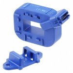
I would like to use a Pololu ACS724 Current Sensor Carrier to measure the amp draw at my alternator in place of a shunt. The V output would be measured by a Dynon general purpose input and displayed by the Ammeter widget.

The parts are available and building a mount isn't difficult. I'm just having a hard time believing that this tiny device can be put in-line on the alternator B lead without cooking.

If you have ANY experience with these devices I would be interested in hearing what you have to say.

Thanks in advance!
 
You can use either one of the GRT Hall effect Sensors. Their sensor definitions files are already included within the Dynon package so you don't need to figure them out. I use the 50A sensor to display aircraft electrical load on my SkyView panel.

:cool:
 
Last edited:
Bill,

The data sheet for the Pololu device shows its range to be +/- 5 amps. The average alternator is more like 50 amps. You are right, it will get cooked.

The devices shown in other posts would be more like it. Keep in mind that those Hall Effect modules require power to operate. Typically 5 volts, so you must have a source for 5 volts and run 3 wires to them: +5, ground, signal. And depending on where you get the 5 volts, you may need a fuse.

That's one of the major differences between Hall effect & shunts. (The Hall effect modules have a little amplifier circuit in them)

From a system design point of view, do you really need to know the alternator's output? It's either working and putting out enough amps to maintain system voltage (around 14v) or it isn't and that will be reflected in a drop in system voltage, down to around 12.5.

If the alternator/regulator goes haywire and puts out too much power then the system voltage will start to rise. If it gets too high, hopefully your over-voltage module will catch it and shut down (or disconnect) the errant alternator, before it cooks your avionics.

I know that lots of GA aircraft have Alternator Load ammeters (like in my Cherokee) but I've never had much use for that info. I think an ammeter in the battery's B+ lead provides more useful information. (more on the topic if interested)
 
Good advice from all. Thanks

I have decided that the ACS724 unit (in a 50A version) would do the job, but the effort required to pot it up and mount it would likely not be worth it.

The loop sensors make good sense and with a little code for the EMS 220 they will all work.

Just a few days ago I actually started a thread (Just Ditched my Ammeter) asking the very question of "why even have an Ammeter?"

Like JLuckey said, the volts will tell me just about all I need to know ... On the path to KISS :)
 
Battery sense

I added my current sensor to the battery leg so i would know if the battery is being drained or charged.
 
...
Like JLuckey said, the volts will tell me just about all I need to know ... On the path to KISS :)
If the reason for the ammeter is only to know if your alternator is working, you probably don't need one. But what if one of the devices being powered is behaving strangely? This might not show up with just the voltage, and with the hall effect ammeter you can see current changes.

My view is that getting this info is so easy and cheap, and it could possibly tell you something useful, so why not do it? I installed mine on the alternator B-lead with a pair of adel clamps, 3 wires to my engine monitor, and the hall effect sensor.

https://www.aircraftspruce.com/catalog/inpages/grandrapidscs-01.php
 
Back
Top