
Van's Air Force
You are using an out of date browser. It may not display this or other websites correctly.
You should upgrade or use an alternative browser.
You should upgrade or use an alternative browser.
Service Bulletin 12-11-09 (Main Landing Gear Upgrade)
- Thread starter Tony_T
- Start date

Not if the torque wrench is perpendicular to the stubby wrench such that the distance from point of applied force on the handle to the center line of the bolt is the same as if no adapters were used. Perhaps someone else can explain it better.Are there any arm calculations to make?
Joe Gores
[email protected]
Member
A great explanation of torque wrench computations can be found at http://www.algeo.com/~joe/KIAT/kiat_3.htm.
Scroll down to Figure 10c, Proper use of Torque Wrench with Extension. It illustrates Joe's example with a 90 degree extension on the Torque Wrench.
Scroll down to Figure 10c, Proper use of Torque Wrench with Extension. It illustrates Joe's example with a 90 degree extension on the Torque Wrench.
gblwy
Well Known Member
No brazing needed
I got a 1/2 inch socket (0.25 square drive) and gound down both ends. I also ground down the square end of an extension. I can now fit the socket on the nut, and insert the extension without the need to braze the two pieces together.
So thanks for the original idea...
Cheers...Keith
I got a 1/2 inch socket (0.25 square drive) and gound down both ends. I also ground down the square end of an extension. I can now fit the socket on the nut, and insert the extension without the need to braze the two pieces together.
So thanks for the original idea...
Cheers...Keith
DonFromTX
Well Known Member
I am having trouble visualizing your solution. Any chance of a photo?
I got a 1/2 inch socket (0.25 square drive) and gound down both ends. I also ground down the square end of an extension. I can now fit the socket on the nut, and insert the extension without the need to braze the two pieces together.
So thanks for the original idea...
Cheers...Keith
RFSchaller
Well Known Member
It's the landing gear attachment point. I would not want to weaken this area by removing material.
joedallas
Well Known Member
Do not enlarge
I agree
This is what started this problem in the first place
I agree
This is what started this problem in the first place
It's the landing gear attachment point. I would not want to weaken this area by removing material.
I've Got A Gap
The mod went well up to re-installing the gear legs. Not sure why, but I'm having trouble getting the U1202 outside bottom gear leg bracket to seat. I see no obstructions, but after snugging it up, I still have a gap at the top of the bolt legs. The gear leg seems to be seated against the wear plate though, but I can still get a fingernail in the gap at the bolt legs.
Anyone else, and/or ideas?
I've just tried the Rt side. Maybe I'll give the Lft side a try today.
Oh, and according to the instructions, we are to install 916-5L washers under the heads of the dash 5 bolts, to aid in torquing from the bold end, only there is none in the kit, nor on the parts packing list. I had some, but what did everyone else do here?
Tom
Oh, and according to the instructions, we are to install 916-5L washers under the heads of the dash 5 bolts, to aid in torquing from the bold end, only there is none in the kit, nor on the parts packing list. I had some, but what did everyone else do here?
Tom
I torqued from the top, on the nuts, using an extension and a crow's foot wrench. Bought the crow's foot wrenches for this job at Harbor Freight. They come in handy.
The mod went well up to re-installing the gear legs. Not sure why, but I'm having trouble getting the U1202 outside bottom gear leg bracket to seat. I see no obstructions, but after snugging it up, I still have a gap at the top of the bolt legs. The gear leg seems to be seated against the wear plate though, but I can still get a fingernail in the gap at the bolt legs.
I am not sure what "the gap at the bolt legs means", but when the bolts are fully torqued, there is supposed to still be a small gap between the U-1202 and the U-1202D-B.
If there wasn't, it would be difficult to know whether full clamping pressure was developed against the gear leg, before contact was made.
Crow foot has limited rotation
A crow's foot will work, however, use care that it is not contacting the edge of the channel cut-out. The crow's foot is a bulky tool and it will only rotate a few degrees before it contacts the edge of the cut-out and the torque wrench will click before full torque is reached.
There have been some good solutions for home-made tools in this thread to allow torquing the nuts on top. Since the nuts need to be torqued on a regular basis, at least annually, the work to make a good tool is worthwhile, or torque from the bottom.
We found it easy to torque from the bottom when we did 737G. Just measure the running torque first with a beam torque wrench, then alternate between the two bolts with increasing torque until the wrench clicks over. We observed a nice even gap at the U-1202 as the plans suggested and Scott explains above.
This raises the question of how to do those subsequent torque checks. Should you loosen the nuts, check running torque, then pull them up tight or should you use the total torque that you logged on first install? It would seem to me that the running torque might be different after the installation ages.
I may be over thinking things...again.
Tony
I torqued from the top, on the nuts, using an extension and a crow's foot wrench. Bought the crow's foot wrenches for this job at Harbor Freight. They come in handy.
A crow's foot will work, however, use care that it is not contacting the edge of the channel cut-out. The crow's foot is a bulky tool and it will only rotate a few degrees before it contacts the edge of the cut-out and the torque wrench will click before full torque is reached.
There have been some good solutions for home-made tools in this thread to allow torquing the nuts on top. Since the nuts need to be torqued on a regular basis, at least annually, the work to make a good tool is worthwhile, or torque from the bottom.
We found it easy to torque from the bottom when we did 737G. Just measure the running torque first with a beam torque wrench, then alternate between the two bolts with increasing torque until the wrench clicks over. We observed a nice even gap at the U-1202 as the plans suggested and Scott explains above.
This raises the question of how to do those subsequent torque checks. Should you loosen the nuts, check running torque, then pull them up tight or should you use the total torque that you logged on first install? It would seem to me that the running torque might be different after the installation ages.
I may be over thinking things...again.
Tony
Last edited:
RFSchaller
Well Known Member
Is the detensioning due to the nut creeping or some other reason? My thought is that a small bead of nail polish or torque seal can serve in place of a torque check if we are only worried about creeping of the nut.
I am not sure what "the gap at the bolt legs means", but when the bolts are fully torqued, there is supposed to still be a small gap between the U-1202 and the U-1202D-B.
If there wasn't, it would be difficult to know whether full clamping pressure was developed against the gear leg, before contact was made.
Thanks Scott. that's exactly what I needed to know. One more item:
After torquing properly, I tested and found that the bolts were easy to turn without holding the nuts. To me that says that I ran out of threads, so I just added and addition washer under then nuts. That worked fine, and there is still plenty of thread past the ends of the nuts, and the bolts seem to have grip, rather than running out of thread. Curious if I am the only one to experience this?? .............Tom
A properly torqued self locking nut is not likely to ever rotate.Is the detensioning due to the nut creeping or some other reason?
The looseness will generally always be a result of the large stack up of heavy gage parts settling in. The rated torque on a bolt is to a large extent generated by the very slight stretch that gets induced on the bolt. If the stack up of parts changes dimension even a very slight amount (a few thousandths), it relieves the stretch load and the torque value drops also.
That is why the retorque after 5 flight hours (that should be enough to settle in all the parts), and then the yearly check during the condition inspection.
After torquing properly, I tested and found that the bolts were easy to turn without holding the nuts. To me that says that I ran out of threads, so I just added and addition washer under then nuts. That worked fine, and there is still plenty of thread past the ends of the nuts, and the bolts seem to have grip, rather than running out of thread. Curious if I am the only one to experience this?? .............Tom
I am aware of one other instance. It must be related to the wide dimensional tolerance of standard AN bolts. After installation and torquing, all the bolts should be checked using the common rule of thumb. No more than 3 full threads protruding beyond the end of the nut.
Adding another washer would be the proper remedy.
Thanks again Scott. As always, your expertise is always appreciated
........Tom
RFSchaller
Well Known Member
Did anyone have problems countersinking the wear plates? So far I've trashed 2 countersinks and only have one hole done.
It appears the countersunk machine screws are retaining devices and not structural. I'm wondering if they are really necessary. Any thoughts out there?
It appears the countersunk machine screws are retaining devices and not structural. I'm wondering if they are really necessary. Any thoughts out there?
Tips That May Help You
I used my drill press, solid clamping of the wear plate, very slow turning, plenty of cutting oil, and fairly aggressive pressure. It worked out just fine. You need all of these to be successful. If you use high speed and low pressure, you will work harden the chrome-molly and countersinking will be almost impossible. I am no engineer, but I think these machine screws play a vital part in making the gear more robust. Besides, I have a lot of faith in Van's folks, and I believe that if it was not that big of a deal, they would not have included the steps necessary to attach these wear plates. Also, it sure make gear removal and installation a lot easier. Worst case effort: Take it to a machine shop and ask them to do it for you.............Tom
Did anyone have problems countersinking the wear plates? So far I've trashed 2 countersinks and only have one hole done.
It appears the countersunk machine screws are retaining devices and not structural. I'm wondering if they are really necessary. Any thoughts out there?
Rich,
I used a countersink bit in a drill press chuck, firmly clamped down the work, used a very slow speed, and oil. No problems. While I agree those bolts seem to be mostly there to hold the plate in place, they may have structural purposes that we are not privy to. I think it advisable to stick with Van's design.
SB kit packing list
My SB kit arrived recently, but I can't find a packing list to check that everything is there. One of the brown paper bags has a large hole in the corner - a small plastic bushing fell out as I took the bag out of the box.
Can anyone scan and email me the packing list please? PM me for email address.
Thanks
RFSchaller
Well Known Member
Todehnal,
I can't believe I forgot about the drill speed affecting the chromalloy cutting. I reset the drill speed today and had no problem with he countersink. Thanks.
Rich
I can't believe I forgot about the drill speed affecting the chromalloy cutting. I reset the drill speed today and had no problem with he countersink. Thanks.
Rich
Look at page 2 of the SB
Thanks - I missed that. I was expecting to find a packing list similar to the subkits. That's what you get for rushing and not leaving enough time to do a job properly!
I'll be back home again and making a start on the SB work next month.
freeflyrush
I'm New Here
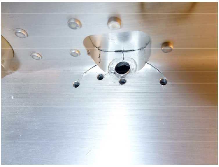
Cracks in Center Section & Outside Gear attachment Holes
Hi Guys
I wanted to get some opinions from you guys.
We have just done the SB-12-11-09 and found cracks in our center section holes for the outside gear attachment bolts.
The right side has some small cracks but our left hand side aft bolt hole has some MAJOR cracks and underneath the hole it looks like a tear with some of the aluminum HIGHER on the left hand side of the crack than the right of the crack.
Vans suggests stop drilling the cracks as per SB and also they suggest an ADDITIONAL doubler plate over the aft hole on both sides.
VANS assures us that this will prevent any further damaged but my partners and i are also concerned with cracks we might not be able to see.
These crack are of huge concern to us especially in such a structurally important part. In one of the pics you can see a crack even running with the grain of the center section.
I know VANS knows best but what do you guys think, any input will be appreciated.
Photo 1

Photo 2

Hi Guys
I wanted to get some opinions from you guys.
We have just done the SB-12-11-09 and found cracks in our center section holes for the outside gear attachment bolts.
The right side has some small cracks but our left hand side aft bolt hole has some MAJOR cracks and underneath the hole it looks like a tear with some of the aluminum HIGHER on the left hand side of the crack than the right of the crack.
Vans suggests stop drilling the cracks as per SB and also they suggest an ADDITIONAL doubler plate over the aft hole on both sides.
VANS assures us that this will prevent any further damaged but my partners and i are also concerned with cracks we might not be able to see.
These crack are of huge concern to us especially in such a structurally important part. In one of the pics you can see a crack even running with the grain of the center section.
I know VANS knows best but what do you guys think, any input will be appreciated.
Photo 1
Photo 2
Last edited:
freeflyrush
I'm New Here
thanks
thanks Geico266
We even considered what the implications were of replacing the entire centre section but we don't even know if thats possible on an existing airframe and if we might do more harm than good.
I guess VANS won't let us fly if they didn't consider their fix safe.
VANS engineers recommended an additional doubler that fits over the TOP of the aft bolt hole to give us spacing from the existing cracks.
RFSchaller
Well Known Member
I agree that Vans' solution is probably the most technically sound since they know the product best. How many hours and under what operating conditions did it take to form the cracks? If they have slow growth rate You should be able to monitor them and determine if the fix is effective. If they stop growing you're OK. I can't speak for Vans but I doubt they would suggest a fix if they weren't confident it would work.
gblwy
Well Known Member
Having reinstalled the gear twice, my advice would be to temporarily install the big inner centre bolt from the bottom without installing the intervening plates at this stage. It's easy to get this through the leg and the central channel, then put a couple of turns on the nut from the top to stop it dropping out again. This secures the leg in the right horizontal position, before you try to get the outside bolts in. And this can be facilitated by lining up the holes from the top with a screwdriver smaller than the hole diameter. Finally remove the big bolt and reinstall from the top, with the various additional plates in place.
Cheers...Keith
Cheers...Keith
freeflyrush
I'm New Here
Thanks Keith
Our top doubler plates are on their way - we still need to stop drill the cracks and send the pics to VANS which i will do shortly. will post some pics of the fix so other members can check it out.
Our top doubler plates are on their way - we still need to stop drill the cracks and send the pics to VANS which i will do shortly. will post some pics of the fix so other members can check it out.
Good tip
Keith, thanks!
This is a useful tip. We just re-installed the gear legs today and your tip of pushing up a large bolt from the bottom to act as a locating pin worked exceptionally well.
Tony
Having reinstalled the gear twice, my advice would be to temporarily install the big inner centre bolt from the bottom without installing the intervening plates at this stage. It's easy to get this through the leg and the central channel, then put a couple of turns on the nut from the top to stop it dropping out again. This secures the leg in the right horizontal position, before you try to get the outside bolts in. And this can be facilitated by lining up the holes from the top with a screwdriver smaller than the hole diameter. Finally remove the big bolt and reinstall from the top, with the various additional plates in place.
Cheers...Keith
Keith, thanks!
This is a useful tip. We just re-installed the gear legs today and your tip of pushing up a large bolt from the bottom to act as a locating pin worked exceptionally well.
Tony
Bill_H
Well Known Member
I've had 5 hours and a bunch of landings since completing the SB so it was time to check the torque. All 4 outboard AN5 bolts required about 1/4 turn to get back to to the torque they were installed with. The inboard bolts were all still proper, no rotation needed.
Had a very small brake fluid leak on the line that goes to the pilot side wheel. Top of that line - the flared fitting. That was a bit of a chore to initially reinstall! I managed to tighten it a little (gotta use two wrenches). Climbed in and cycled the brake several times. Still a small leak. Tightened some more - total about half a turn - retested OK. The level in the brake fluid reservoir had only gone down about half an inch. Just an FYI, the brake fluid leak was visible when the cover plate was removed and looking up at the fitting.
Had a very small brake fluid leak on the line that goes to the pilot side wheel. Top of that line - the flared fitting. That was a bit of a chore to initially reinstall! I managed to tighten it a little (gotta use two wrenches). Climbed in and cycled the brake several times. Still a small leak. Tightened some more - total about half a turn - retested OK. The level in the brake fluid reservoir had only gone down about half an inch. Just an FYI, the brake fluid leak was visible when the cover plate was removed and looking up at the fitting.
MLG bolt retorque
Also recently did the MLG retorque after the 5 hours and found 3 of the AN5 outer bolts needed 1/4 turn and one needed 1/2 turn to reach spec and all the inner bolts were solid.
Also on another plane (Bogash N737G) the check was similar.
Also had a couple of pesky leaks, but mine were on the pipe threads of the brake fittings up under the channel. Had tried to fix these in the past with common thread sealants but the leaks would reappear as a small red stain after a number of hours. Finally, at the MLG upgrade SB got these stopped using Loctite 567 sealant as recommended by the Matco Brake people.
Tony
dick seiders
Well Known Member
gear leg mod
I am into my condition insp. period, and am doing the mods first. I put off the gear mod till now as I never had any issues with the skin etc. I have been on it since Sat. and would like to say I must be the slowest builder/repairman in the world as I have put in most of the time Sat. thru today and am only at the place where I will clean, deburr, assemble and touch up with primer/paint on the doublers. When that's complete I will go on to the drilling, fitting, and reinstalling the legs. Sorry Scott, but this is certainly not a weekend project. At least not if you care about the quality of the work. Also doing a job like this for the one and hopefully only time requires all the usual finding of tools running to ACE Hardware, reading all the info etc., etc. which takes as much time ,or more than the actual details work. I am not complaining. I'm just here for info. I tried reading all 30 pages of the thread, but my eyes glazed over at 19 or so. I jumped to the the last page and still need to ask a question. Everything is as per the book so far. I have the good fortune of having a friend with a mill so cutting the chamfer on the gear brackets was a breeze. The problem is I have been unable to "tap" the pin bushings and move them anywhere. I do not wish to destroy them so gave up on the "tapping". Is the any reason why I cannot simply use a AN3 bolt and lock nut in place of the Cherrymax rivet at the impossible place to rivet w/o moving the immovable bushing? After all the AN3 bolt is stronger than the rivet so am I going off the mark here or what?
Comments greatly appreciated.
Dick Seiders 120093
Dick, I bought a Cherrymax G27 riveter because the ones I had wouldn't grip the cherrymax rivets. As a bonus, I found that the barrel of the riveter was slim enough to access that rivet without moving the bushing. Tight fit, but it worked fine. Might be worth trying a different riveter first.
http://www.spenro.com/cherrymax-hand-riveter-p-109.html
http://www.spenro.com/cherrymax-hand-riveter-p-109.html
Dick,
You are in the company of aviation Olympic Champions. Tony and I did mine first and I think we used 75 man-hours, maybe more - working fast and together (opposite sides.) Then we did Tony's - a lot more man-hours - maybe Tony has the numbers. And -- we didn't pull the fuel tanks.
I can be quite a fast worker, but am amazed at some of the reports here on the Forum. Clearly, my skills are not near what I thought them to be.....
My advice, take your time, do it right, and don't try to match some of the faster guys here on the Forum.
Bob Bogash
N737G
LittleJoeA
Well Known Member
I manufactured an aluminum cup and large washer and with some 1/4 " all thread used it as a press to move the bushings. I didn't want to risk damage with a hammer and bock.
dick seiders
Well Known Member
Thanks to all who provided input. I asked Vans about using an AN3 bolt on the hard to get at cherrymax locations, and they did not feel that was necessary as I just needed to move the bushings. Well I tried again with a fitted bushing insert made of poly carbonate and pounding it, prying it, and cussing it did not move squat. Appreciate the bolt squeeze suggestion, but am really concerned now about breaking them loose as tight as they are as they may not ever refit. I tried my hand puller and it appears to fit the dreaded corner position ok so tomorrow I intend to pull the c-max in the corners with it. I hope it works. I don't understand why c-max are used in the first place as assuming the AN3 required too large a hole increase it's obvious a #8 screw would handle it nicely, and the screw has a greater shear strength than the c-max anyway. Wanting to follow Vans instructions I am staying with the c-max, but don't understand the logic as the screws would be SOOO much easier to work with in that location. All parts are primed and ready to rivet so maybe I will finish the job by this weekend. If so I will have invested more than 60 hours, and some of those required a helper as well.
Dick Seiders 120093
Dick Seiders 120093
dick seiders
Well Known Member
Another somewhat frustrating day on the gear mod. When pulling the c-max that attach angles to c channel (the hard to get at locations) two of the rivet stems separated from the rivet before the rivet was fully set, and a third one I did not have fully against the c channel apparently so when setting it the head is .050" above the channel. So I learned how to remove cherrymax rivets. One down, two to go. Of course it may be me as I haven't worked with c-max before, but don't usually have this type problem. In addition I have to drive to A. Spruce tomorrow to buy about twenty more of the rivets so I have enough to finish the job. (Why didn't the job just call for #8 screws?)
Lastly the grip length of the CR 3213-4-5 is ,250" to .313". Isn't that a bit short for the channel plus two .025" angles? Did anyone use CR3213-4-6? Grip length for those is .313-.375" I may buy a few in the event the 5's keep breaking. Did anyone have these issues occur, and if so what was your solution? Appreciate any feedback.
Dick Seiders 120093
DonFromTX
Well Known Member
Sounds like you are right on track with most of the rest of us. I fought those cherry max jobs the same way, a couple of us decided the rivets did NOT come with the right grip length! Vans countered that the extrusion channel varies in thickness, so maybe ours were thicker or something. The "fix" is a good one I feel, and easy to apply, except for a few stubborn cherry max rivets.
I had to drill out a couple that were not fully seated too, they don't pull in tight like the LP 4 3 jobs we are so used to using, so if they are not quite all the way in - they will have to be drilled out. Thankfully there are not too many of them..
I had to drill out a couple that were not fully seated too, they don't pull in tight like the LP 4 3 jobs we are so used to using, so if they are not quite all the way in - they will have to be drilled out. Thankfully there are not too many of them..
RFSchaller
Well Known Member
I don't recall any issues installing the Cherry Max Rivets. Maybe I was just lucky.
DonFromTX
Well Known Member
Or maybe just more skilled in their use.
I don't recall any issues installing the Cherry Max Rivets. Maybe I was just lucky.
RFSchaller
Well Known Member
Trust me, Don, skill played no part!
dick seiders
Well Known Member
I'm a slow learner regarding the Cherrymax. I not only broke a few , but had to drill out all on the right side of c channel due to fact the u1202t was not flush with the u1203u (top pc). Now this was my error as even tho I had the top and bottom angles cleco'ed I did not catch the fact that the bottom was not flush to the top, and as a result all 4 rivets had insufficient grip on the lower angle. This brings to mind a point to make with any who have not yet performed this upgrade. Be advised that the u1202t (lower angle) needs (in my opinion) to have about 1/8" to 3/16" trimmed off the fwd end as a bulkhead rivet interferes with the correct mating of the two angles. This will totally eliminate the interference problem and save whoever heeds this advice the need to remove the rivets. (no small task). Additionally removal of the rivets (due to the tight quarters encountered) can cause a fair amount of bending of the angle as driving out the body of the rivet will bend the devil out of the bottom angle.
I have completed the riveting of the doublers today, and happy to say that after installing the best part of 100 of these things (including those I screwed up) I am proficient with cherrymax installation. I would definitely recommend the use of a hand rivet puller as the air operated pullers do not perform as well. The hand tool enables you to tell exactly what is happening with the c-max as you pull it thru the three stages of a successful installation. Also I used my standard store supplied hand puller. It was not necessary to spend 90 bucks on the G-27. Starting gear leg doubler work tomorrow.
Dick Seiders 120093
Piper J3
Well Known Member
SB 12-11-09 - Center Section Modification
I bought my RV-12 early SN (120058) from the original builder with 48TT knowing that SB for Center Section and Fuel Tank were not completed. I flew for a year before completing these two service bulletins. I guess I was having too much fun and the RV smile wasn?t wearing off. So, in my case the Center Section Modification was completed at 205TT. No cracks were found during the work. This area is given extra care for visual inspection during Annual Condition Inspection. No cracks at current 521TT.
The reason for resurrecting this thread is to see how this fix is holding up to the test of time. I fly off of a private grass strip that is not very smooth. The runway has not been rolled for the past two years and frost heave in the winter has worked its magic. I would imagine my landing gear has been subjected to near maximum abuse short of training flights and really poor landings.
Has anyone noticed new cracks forming or propagation of existing cracks that were stop-drilled during the SB?
As a reminder, the attached photo is included in SB 12-11-09.

