What's new
Van's Air Force

Don't miss anything! Register now for full access to the definitive RV support community.

N159SB G3X Panel Upgrade Status

That panel looks sweet on the ground but AWESOME in action. Congrats. I'll bet you were fighting some winds as well yesterday if you were ANYWHERE near the area I flew in yesterday. Looking forward to the hands on tutorial video which I'm sure you'll produce as you get comfortable!
 
I have had several people request the DXF file for the G3X screen cuttouts.

Most of these folks were trying to use the file provided by Garmin in the Front Panel Express panel design software. That file will not work because it has some extra information included that FPE does not know how to deal with.

I removed this extra info and saved the file that will work in FPE here:

http://s000.tinyupload.com/index.php?file_id=03210759528566755874

Hope this helps!
 
I plan to have the following angle adapter machined to try and get the PFD#2 angled 10? toward the pilot. This should make it 100% usable by the pilot as well as the passenger.

23h8twn.png


It is not bad as it is but this slight angle will get the eyeballs a little more on axis with the screen....
 
Brian nice job on the panel and write-up. I am working on a new panel with G3X and some of the same components as you. I have gone back through all 21 pages and do not find a discusion on antenna location for all your external antenna. I am now adding doublers and have decided on two com antenna on the bottom aft the spar but the transponder and ADS-B antenna have me puzzled for a good location. You probably used existing locations for your existing antenna but I wondered where that was and where did you add the ADS-B? I was considering the DP blade antenna for both trans. and ADS-B beside the fuel vents at the firewall but that does not give them the required 3.3 foot seperation.
 
Keep in mind that xpdr/ADS-B antennas require a ground plane like all other antennas, 8" dia min. required for xpdr/ADS-B.
 
Life is full of compromises and I had to make some with regards to the antenna locations.

I used the existing xponder antenna which is just aft of the firwall on the co-pilot side right next to the fuel vent. Works fine there.

I used the existing COM antenna locations which are on the bottom in the outboard most bay between the seat ribs and just aft of the spar box.

The GDL-39 antenna was where I made a compromise. I could not get the separation they recommend with this antenna without running another coax to the aft part of the airplane. I did not want to do that since I am out of room for wires. I also did not want to add any more weight to the tail of the airplane since I am already a little tail heavy.

So I put it on the belly just in front of the spar box on the pilot side. It has the recommended distance from the xponder antenna which I think is the most critical but not the COM antennas. It seems to work fine however.
 
Thanks Walt and Brian,
I was thinking about compromising the GDL antenna but since I have room for cabling, I may go ahead and run the GDL mid-fuse aft of the baggage bulkhead. This will still be a little bit of a compromise with the ground plane on the transponder but it seems to work for everyone else.
Brian, I assume your GMU-44 is in the tail and temp probe in the wing?

Yes, The GMU is on the deck under the HS stab in front of the HS spar. The OAT probe is mounted in the inboard wing inspection cover on the pilot side.
 
I made another test video to test my home HD camcorder for how well it might be used to make videos from the cockpit. I love the color and the good focus but it does not have a very wide field of view...

Anyway this video shows the startup procedure I am using with the new panel or as good as I can show it while holding a camera in one hand....


I need to configure my startup screen to be the full page EMS page on the MFD so that I don't have to manually do that.
 
Fuel Sender Calibration

I mentioned before that I would post some info on how I have calibrated the new system. One of the items that I had to do was calibrate the fuel level sensor.

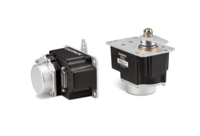
For background....I have the standard Van's style capacitive fuel level senders.
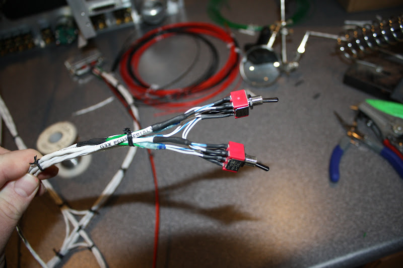
I also chose to use the Princeton 2 point capacitive to voltage converters. These converters allow the end user to calibrate them to the full range of capacitance change empty to full. This allows the user to take advantage of the full span of voltage range available which is 0-5v. This makes it nice since I doubt there have ever been two of these senders/tanks that came out with the same capacitance change profile across the volume.

So the first step after installation is to calibrate the empty and full end points into the Princeton converters.

So to begin this process you must empty the tanks if you have fuel in them and I did....

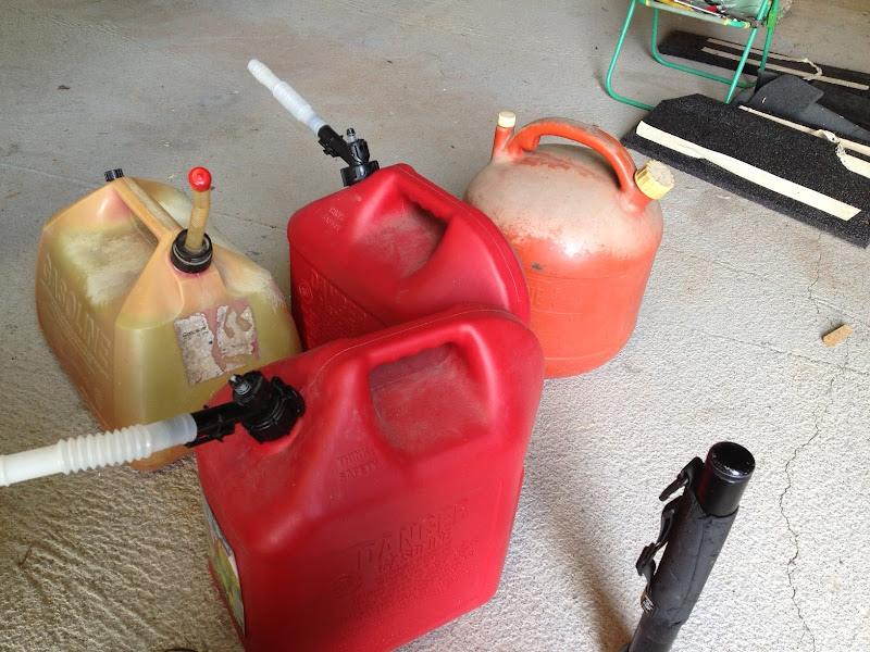
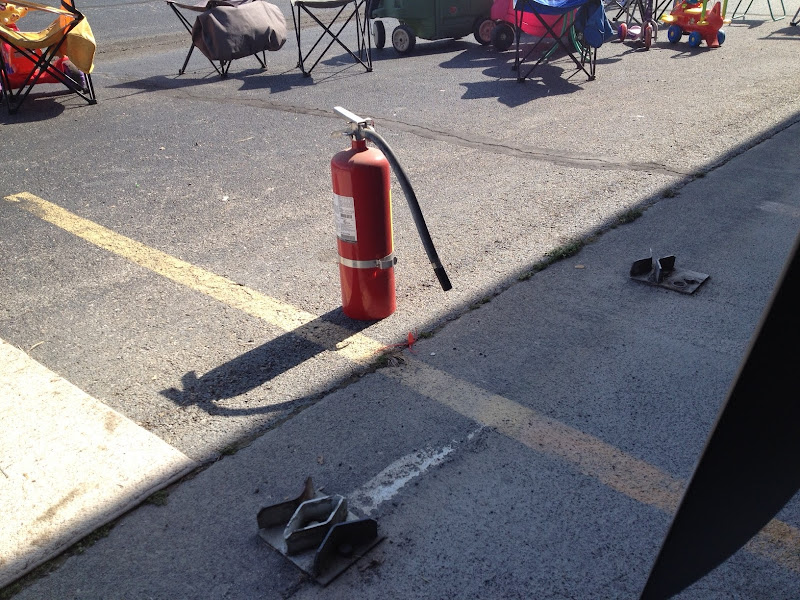
Before I started, I grounded the airplane, got out the fire extinguisher and raised the tail up into level flight configuration. I had ~23 gallons worth of gas jugs available, a funnel, paint strainers and I had about 25 gallons of fuel on board to use for the calibration.

photo%252021.JPG


This needs to be about 100 times bigger to be of any benefit in an actual fire but as Si would say....Hey! It's all I had Jack!
photo%252022.JPG


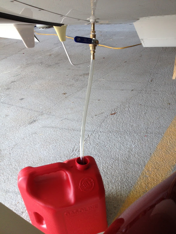
I came up with this apparatus in order to make the draining as safe as I know how. The last time I did this I had fuel everywhere and all over me. I was a human torch waiting to go off. Even with this stuff, you still need to get the quick drain out and this installed. This will result in some fuel being leaked so be careful! I also had a box fan in the rear behind the wing blowing the fumes out of the hangar!

photo%252020.JPG


So once the tanks are empty, I followed the Princeton directions on how to calibrate the empty set point. Pretty easy...hold the button in while turning on power,release and the left light will blink. Press the button once while empty and the unit will set the empty point. The right light will then blink waiting for you to fill the tank.

I filled the tank full while pouring the fuel thru 3 paint strainers in the funnel. I like to strain my fuel when I do this to get out any trash. Once the tank is full and you give it time to settle, press the button again to set the full point. This will cause the unit to store the calibration and reboot itself. Once it is rebooted, walla - you have a 0-5v signal. 0 when empty, 5 when full.....

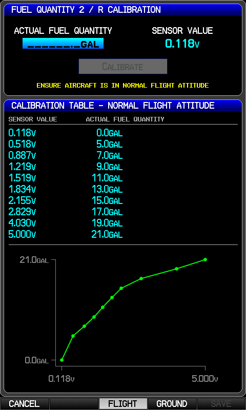
So now we have one tank converter calibrated the next step is to calibrate the EMS to use these signals. Since the converters are only 2 points and the tanks/senders do not produce a linear signal due to shape and variables built into the senders, one must teach the EMS what voltage is what amount of fuel.

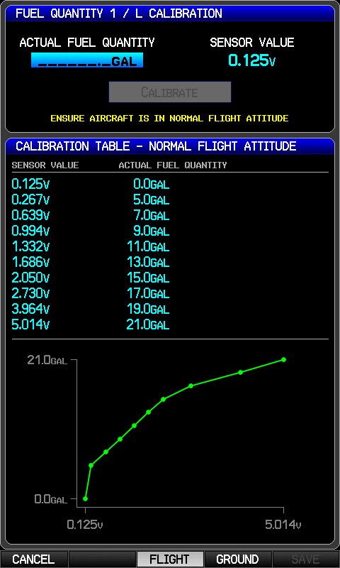
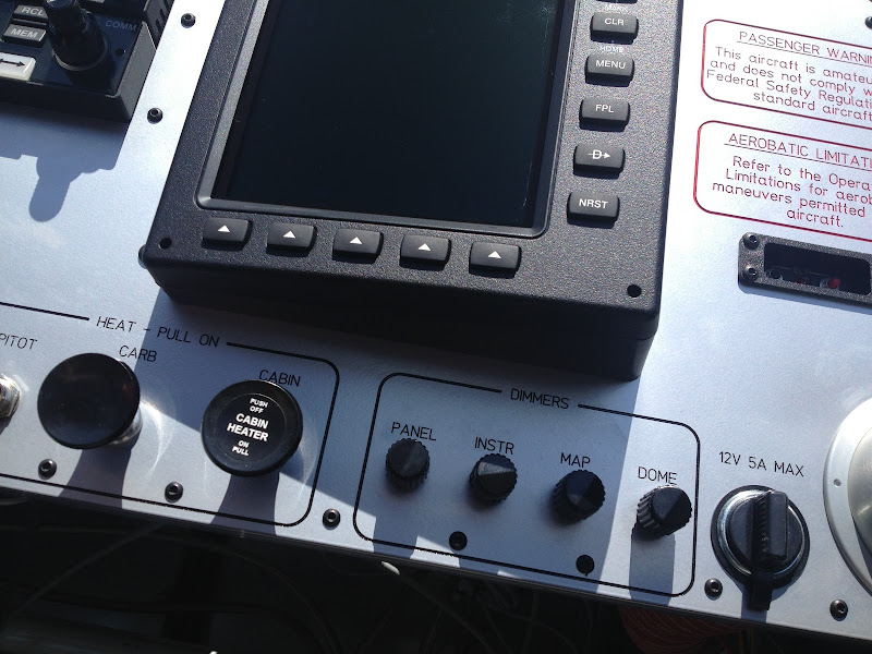
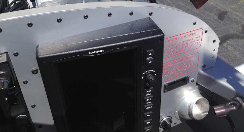
To do this, the G3X has a fuel level sender calibration page in the configuration mode. It is a nice page that basically reads the voltage, you tell it what amount of fuel that represents and then it lets you store these calibration points in sort of a lookup table. It even draws a nice line chart of the calibration points so you can visualize the non-linearity of the senders. There is a method available to delete stored points by selecting the point and pressing the CLR button. There is not however a way to manually tweak a point by manipulating the stored numbers. This would be a nice feature to be able to fine tune the calibration. Once you store the calibration, if you insert an SD card, you can backup the fuel level sender calibration to the card for restoring later if you need to.

So since one tank was now full, the jugs are empty and the G3X allows you to either work you way up by adding fuel or work your way down by subtracting fuel, I chose to subtract fuel by draining it 2 gallons at a time and then storing a calibration point. Be careful to allow time for the readings to stabilize before storing and do not shake the airplane while doing this.

20130316_154658.jpg


So now I have one side fully calibrated and the tanks are both empty again, the jugs are full.

I just repeated the process for the second tank.

20130316_154709.jpg


Notice how similar the profiles are for the two calibration curves.
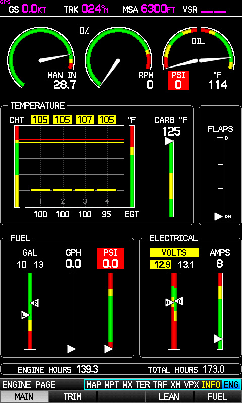
Once it was finished, I had two empty tanks and full jugs. So I put 10g in the pilot's side and ~13g in the co-pilots side.
Here are the results of all of this work...pretty good...it matches what I put it!

20130316_163702.jpg


One note: once I was down to the 3 to 0 gallon range, there is not much if any of the senders still in the fuel so the readings don't change much.

This process takes several hours start to finish and is a high risk operation. The risk of fire, property damage and personal injury is really high if you ask me. This is not something that I like to do but it has to be done....The G3X allows for another calibration curve for ground ops but the risk is not worth it in my opinion. On the ground I use the eyeballs in the tank method anyway!


Also today I tweaked some settings on the VP-X Pro. I had the pitch trim button working backwards as well as I wanted to enable the feature on the flaps that allow the you to command the next flap position before the flaps get to the previously selected position. Also tweaked the flap extension lockout speed as well as the point where the CHECK FLAP SPEED warning pops up on the screen.
 
Last edited:
Brian, thanks a lot for all of the info you are putting out in this thread. It has made my install much easier.

If you're going to Oshkosh this year, I'll happily buy you a beer.
 
Last edited:
Great job Brian. I think that I can safely say that there are many of us here now and many yet to come that will benefit a great deal from your dilligent postings. I absolutely have. :p
Thank you!
 
Brian, great thread!

I notice you have a 'ground' calibration routine for the fuel sender as well. Do you plan on going through this all over again with the tail in the 'ground' position? When I did my calibration years ago I was able to bribe the fuel truck guy to spend an hour or so with me and he gladly did it. But I started from zero and added 2 gallon increments in both 'flight' and 'ground' modes all the way up to full, left and right. It took some planning. I had a friend help with raising and lowering the tail on its stand. Was just curious if you could do it this way. :confused:

Oops, re-read your post and see that you don't intend to do this again! Don't blame you, the difference is not significant relative to the overall accuracy of the system.
 
Last edited:
Looks like my new panel is getting an upgrade....:p

The new dedicated autopilot interface is a no brainer to me. It is almost as if there was a place made just for it in the new panel layout....

click for big version:


This new dedicated interface will solve one on the issues that I was already having with my new panel layout and that was the need to switch hands on the stick in order to turn off the AP. This was annoying especially at minimums on an approach!

Not sure yet on the transition to the new Garmin servos. Will need to noodle that one.

Most definitely thinking of adding an additional AHRS to the system however! I want my AOA back!
 
Last edited:
This new dedicated interface will solve one on the issues that I was already having with my new panel layout and that was the need to switch hands on the stick in order to turn off the AP.

I have an AP disconnect on the stick. Also, same button will engage the AP if held in for a few seconds.
 
I have an AP disconnect on the stick. Also, same button will engage the AP if held in for a few seconds.

Yep, I never could convince myself to change to stick grips with more buttons. I also did not want to run any more wires to the stick. I could add a CWS button right above the throttle for this purpose but I like the dedicated AP interface better since it brings many more features to the table.
 
AP on the stick

I have an AP disconnect on the stick. Also, same button will engage the AP if held in for a few seconds.

I flew Doug's RV-6 with the AP on the stick and discovered it engaging as I flaired for my first landing in the plane. An exciting moment that (fortunately) immediately grabbed the attention of both me and my pilot/passenger. An AP on the stick is one of those things that might be very handy for someone who regular and only flies a plane but that experience convinced me to keep the AP off the stick!

Love seeing the new Garmin toys and glad to see they have made it easy for folks like Brian to retrofit into a panel. Good job!

I am in the same camp as you Louise... I struggled with the decision to leave all the buttons off my stick. I am one of those that would accidently push em all the time. Our cockpits are small so its no big deal for me to reach to the panel.
 
Two methods

I have separate toggle switches on the stick to separately disable vertical and horizontal a/p. the easiest direction to bump them with my knuckle, away from me, is the disable direction. It takes stretching out my thumb and pulling the switch towards me to re-engage.

Additionally I have a switch right above my throttle that I can reach with that thumb without taking my hand off the throttle which completely depowers both servos.

It remains to be seen how well this will work irl
 
Got in another flight today in between bad weather. Logged a little more than an hour on the bird.

Just getting acquainted with the new panel and learning to trust it, learning to trust that I know how to execute procedures and knowing what the response from the system will be.

Overall it seems the G3X is a joy to use. There are some significant differences in how it works vs my old panel so I have to break some habits that I had developed and learn some new ones.

The capability of this panel far exceeds the capabilities of the old panel so with that added capability comes additional complexity. Not in a bad way, just more stuff to know.

Today I shot three fully coupled LPV approaches into runway 23 @ KMOR.

Everything seems to be working pretty good but I have a little tweaking to do on the GX Pilot. During turns where the G3X is driving the GX Pilot over GPSS/GPSV with its directions coming from the GTN650, I am getting some pitch axis porpoising during the turns like the turn around portion of holds and procedure turns. I am working with Lucas on this issue and I am sure that he will help me iron out this issue. The rest of the time, the pitch axis works great.

Had good ADS-B traffic throughout the flight today. It is truly amazing how much this TIS-B helps with the traffic avoidance. Eyeballs outside primary with the occasional glance at the screen helps a ton! I have identified more traffic out the window in the past 4 flights than I ever have before and I have had a Zaon XRX for most of my time with my airplane. I can't imagine how much traffic would go unnoticed with no traffic avoidance system at all.

There was one weird anomaly today however. Part way thru today's flight I was not getting a full TIS-B uplink icon like I have had on prior flights. The traffic data was there, just no icon....will have to watch it on the next flight to see if this happens again.
 
Last edited:
There was one weird anomaly today however. Part way thru today's flight I was not getting a full TIS-B uplink icon like I have had on prior flights. The traffic data was there, just no icon....will have to watch it on the next flight to see if this happens again.

I thought I would update the thread on this issue. Turns out this was not an issue with my plane but instead an issue with the local ground stations. (UPDATE: Later I found that this may not be true)

I did not like this situation since without the uplink icon, one does not know if they are receiving traffic data or not. A false blank screen is worse than no screen at all in my opinion. I do however always consider any traffic/collision avoidance system as a secondary system. Primary is eyeballs out the window, head on a swivel.

Typically above 2000ft MSL & bellow 4500ft MSL around my airport I can receive full signal on two ground stations. I get more the higher I go. I flew one additional hour long flight the next day after this flight and had the same results. I was receiving full ground station signal, FIS-B services and I was getting full TIS-B services however my system was not confirming that I was a full TIS-B client. The G3X system and the 796 "X" out the TIS-B uplink icon whenever you are not fully qualified by the ground stations. Keep in mind that I had flown several flights before these issues showed up without any problems at all.

After working the typical troubleshooting steps and talking to Team X at Garmin, we both concluded that this must be a ground station issue. I went on a mission to discover who and how one would find out about TIS-B service outages in the area. The first place I checked was the local NOTAMS. The only one I could find was the FDC NOTAM that was issued when the ADS-B services went online in my area. That NOTAM stated to check with the local FSS for system status and to report outages. That's what I did and the guys at the Nashville FSS had absolutely no idea what I was referring to when I spoke of ADS-B, FIS-B, TIS-B or ADS-R services. The folks I talked to on the phone were completely clueless....

That lead me to the FAA's Next Gen website where I found an ADS-B email to contact for questions/issues. I did that and got a reply back within a few hours. They asked me a few questions and told me they would be in contact with me shortly. About an hour later, I got a call from some very nice lady in D.C.. She told me that she would check into why the FSS guys were clueless and that she would also check into the TIS-B service issues in my area. She must know what she is doing and or has some pull because in short order, the services were back to normal....

The takeaway for me is that at this point it does not appear that the system is flawless. Before you go crazy ripping apart your system looking for issues I would try to determine if the FAA's side of things are working correctly. Don't just assume that a NOTAM will automatically be published in the event of a failure.

I do want to continue to promote the TIS-B services however. It is truly amazing how well this system is working in my area. I have yet to spot an aircraft at my altitude or above that is not also being shown to me via TIS-B when I am receiving TIS-B services. So far it looks like if the terminal, regional and ARTCC radar stations in my area can ping the aircraft, I get em on my screen. I have seen some that have no data associated with them so those look like they may be non-transponder equipped targets? I have been monitoring the local radio calls and cross referencing pilot position reports with the TIS-B data and so far they have been amazingly well represented if they are at a typical radar coverage altitude for my area.
 
Last edited:
A friend of mine was able to use his CNC equipment to make me an angle adapter for my Co-Pilot side PFD/MFD #2 using the solid model I designed.

This angle adapter angles the screen toward the pilot 10?.

I had it machined out of black UHMW since that is all I could find for scrap material. I would have preferred black Delrin but the UHMW seems to be gonna work fine. The adapter is drilled and tapped to accept the captive screws of the screen and four screws from the back of the panel thru the original screen mounting holes.

IMG_0617.JPG


IMG_0619.JPG


IMG_0618.JPG


IMG_0621.JPG


I flew a short flight today and this really makes the third screen usable by both the pilot and the co-pilot. Much improved readability from the pilot seat and it makes the knobs and buttons easier to access. I think I like it!
 
More followup on the ADS-B TIS-B Uplink

Until last weekend I have still been experiencing occasions where I was receiving TIS-B traffic uplink data but I was not being qualified as a full TIS-B client.

On this flight:

50kyrt.png


The TIS-B was up and down like a yo-yo. I found that strange since in that area and at that altitude, I am always near 100% signal on at least two ground stations.

So I decided to investigate a bit more....my assumption at this point is that I found the intermittent issue.

I took the xponder antenna connections lose and checked them, rang out the cable and connections, etc. No issues found.

I decided to check the nut on the TED Xponder antenna installed aft of the firewall inboard of the vent line fitting. With a cresent wrench up on its nose, I was able to turn it about 1/2 a turn. Hmm...maybe that was it. Poor grounding of the antenna? Weird things can happen at xponder frequencies so a little thing can have a big effect.

I flew again that same evening and the signal and status were 100% normal. No up and down status icon and no dropouts of the traffic data even when flying some of the same headings and altitudes where just an hour before was giving me problems.

The next day I completely removed the TED antenna, cleaned the area where it mounts, and reinstalled it with a socket wrench ensuring it was very tight.

The past several flights have been rock solid....

The moral of the story is:

Just because you can pass a xponder/static test and just because you are being seen by ATC and just because you are getting reply indications on your xponder, and just because you are getting full ground station signal on your ADS-B IN receiver does not mean that what you are outputting meets the strict requirements of the new ADS-B systems. Not sure what a marginal ground on the TED antenna was doing to my xponder output but the ADS-B ground stations did not like it!


One more thing:
You should see a fat man put his knee's in the seats of an RV7, duck his head down under an extended instrument panel, face down and go after his xponder nut and then get out again....It is very entertaining! :eek:
 
Last edited:
GX pilot

I'll be reading to see if you can smooth out your GX Pilot turns. I have the same issue on my G3X and GX pilot. the autopilot is slow to compensate while loosing the horizontal component of lift in the turns. Not a big deal for me either, I would just like to smooth it out a touch.
 
I'll be reading to see if you can smooth out your GX Pilot turns. I have the same issue on my G3X and GX pilot. the autopilot is slow to compensate while loosing the horizontal component of lift in the turns. Not a big deal for me either, I would just like to smooth it out a touch.

I have not been successful to eliminate this issue. Lucas had me turn down the max bank ability of the GX Pilot to the point of where it was not able to stay on the commanded course lines but this did not solve the issue.

After returning to the default bank limit, the best I have been able to do was to turn down the vertical gain by one notch to 2 and to turn the static lag up one notch to 1. This helped but the issue is still there.

I have tried running without the static line attached and it does the same thing.

Not really sure where to go from here to significantly improve or totally eliminate the issue. The end user level of settings are limited.
 
I have seen a number of transponder problems caused by bad cables (old RG58) bad antennas, bad connector installation, crushed cables, frayed/broken shielding at the rack connector etc.. Symtoms vary but I usually see such things, SLS fail, pulse width out of limits, pulse spacing out of limits and reply jitter fail.

Unless the shop that did your test was using the latest equipment (I use the IFR6000), the older test equipment does not even check some of these parameters so you would never know there was a problem.
 
For those that thought this upgrade was done and over with...

SteinAir informed me that my new GMC305 and Garmin servos are on the way...he is quickly fulfilling his T shirt creed!

gmc305.jpg


GSA-28-Servos11.jpg


The GMC305 might make it into the panel before Osh if I can get the prop swap process completed in time....servos will have to wait!

Also have a second AHRS GSU25 coming to give me back my AOA capability and to add some redundancy. That will have to wait till after Osh as well.

gsu25.jpg


Here is where I am going to mount the GMC305:

g3x%2520w%2520650%2520and%2520GMC.jpg
 
Last edited:
Behind the panel?

Brian, your thread has been a fantastic reference for me in my project that is VERY similar to your panel hardware... Thanks for your time to make your hard work public.
I would love to see some pictures of your wiring behind the panel. Specifically, I am curious about how you routed wires, your wire secure points, and how you moved from behind the panel to behind the sub-panel. I am struggling finding good paths while keeping those wires that don't play nice with other wires apart.

Thanks again for your help!
Mark

Mark,

I have tried to get good meaningful under and behind pics and have never been able to get good ones. Even with a wide angle lens, it is so tight back there that it is hard to get enough context out of em and good focus.

Keep in mind that my panel was a third generation retrofit and that it was done in a finished airplane without very good access. The power distribution was also replaced with a VP-X Pro so that even made it more of a challenge. That being said, I had to make some compromises in order to make it happen. The wire routings and logical order may not be optimized due to constraints or lack of access. If I were doing the same panel in an unfinished plane without the front top skin in place, the work and arraignment would be much different.

Since I built my avionics harness on the kitchen table and laced it all up before install, most of my bundles that cross the subpanel just route under it with a clamp on the bottom flange of the subpanel.

As far as power wires and signal wires, in these airplanes, it is difficult to keep em completely separate. Do the best you can and hope for the best. Garmin's use of all shielded cable helps a ton to prevent issues. Follow their directions to the best of your ability when it comes to shields, shield drains and grounding and you will be fine....
 
Worked on the TT GX Pilot and TT Gemini PFD harnesses today.

These Track Source switches add complexity to the situation and I am not sure they are worth it or not. While they do add some redundancy, 99% of the time they will be in the EFIS position.

Christer at SteinAir told me that they don't put these in as many panels these days...

IMG_4970.JPG


Hi, im installing princeton to my G3X please tell me what pin do you use in the gsu 73 to conect it.

Regards
 
Hern?n,

Sorry I missed this post.

I used the install manual for a guide on where to land these wires. I ended up having to run a separate 12v lead to the Princeton converters instead of using the built in 12v excitation power provided by the GSU73 because the Princeton units would draw too much power on startup and cause the GSU73 to shut down the excitation power output.

Take a look at page E-7 in the Rev.K of the install manual and use the bottom example.

There is also this post you can go by:

http://www.vansairforce.com/community/showpost.php?p=624949&postcount=5
 
Beautiful panel. Would you mind sharing what made you switch to Dynon from Gemini?

Very inspiring and informative thread!
 
Beautiful panel. Would you mind sharing what made you switch to Dynon from Gemini?

Very inspiring and informative thread!

Thank you.

Let just say that the Gemini PFD and my airplane could never learn to get along. Since I love my airplane more, I had to come up with another backup solution.

After much thought on the matter and considering the options and what modifications would have to be done to mount a new box, I decided that the D6 deserved a chance to see if it can get along with my plane.

The G3X system and my plane made friends instantly so it is staying!

Here it is all ready for action...Only thing left to do is calibrate the compass.

142e8pf.jpg
 
Last edited:
Brian, thats just an awsome panel! I think it is a great inspriation for builders to see and get great ideas from. Not to mention motivation.
 
Brian, thats just an awsome panel! I think it is a great inspriation for builders to see and get great ideas from. Not to mention motivation.

Thank you.

I have to pinch myself every time I fly this thing. I am truly blessed beyond my wildest dreams to be able to have such a plane.

While I am just the assembler, the real credit goes to the manufacturers of this awesome equipment we have access to these days. Thanks to them for bringing such awesome products to the market at a price normal people like me can afford.
 
Last edited:
All I can say is WOW. look at all those neat looking lights and things (?) One of these days I'll figure out what all of it does:eek::D
 
G3x Panel Upgrade

Brian,
A couple of questions if you don't mind. First of all how did you come to your decision on the G3x? I am at the stage where I am starting to think about my panel, there are so many choices that I find it a daunting task. What was your thinking about a standby autopilot, or did you already have that one? Your panel is awesome, I want one just like it. I'm tall and I didn't want that extra sheet metal hanging down at my knees! You've proven that it can be done. Did I understand that if you were building from scratch you would not put the two EFIS/GPS switches in? Thanks for the big help in getting me started on my panel.
 
Brian,

You have definitely designed a panel I could live with. Curious though...how are you going to switch which AP head is controlling the servos?

I may have missed it somewhere.

Awesome sauce...I need your panel file again.
 
Brian,
A couple of questions if you don't mind. First of all how did you come to your decision on the G3x? I am at the stage where I am starting to think about my panel, there are so many choices that I find it a daunting task.

I made a matrix out of what features I wanted in a panel. I also cross referenced that with what I already had that I planed to reuse to keep the cost down. Then last but definitely not least, there was the budget that I had to work with. At the time Garmin had everything I wanted which included a full ADS-B OUT and IN solution. Garmin had been making a major effort to play in the experimental market. This included lowering prices, creating experimental products, creating the Team-X, providing outstanding support live on the forums etc.

After getting to know Steve and Matt with Team-X and seeing how well they handled supporting me with my GNS430W and 796, I knew Garmin was committed to the experimental market long term.

I liked the layout options that the portrait style screens allow with the G3X system. With a SBS RV, splitting two large screens with the radio stack puts the second screen too far away to be used easily in my opinion. The G3X just fit my vision for a good layout better.

I loved the detailed documentation, first class connectors, and overall system architecture of the G3X.

Nobody knows how to integrate with the GTN650 better than Garmin so that was another big plus. At this time, nobody else draws the full procedures on the moving map like Garmin does.

There is much more to the story but I will spare you the boring details. It is very much a personal decision that everyone must make for themselves. Look at your mission, budget, wants and needs and wait as long as you can before committing!

What was your thinking about a standby autopilot, or did you already have that one?

I personally think there are pros and cons to the standalone AP.

Some of the pros are that they provide an independent means of keeping the greasy side down if the EFIS goes INOP (within limits). You can also drive them around with their knobs or with some of them connect directly to an external navigator.

Not really a con but in some cases, the EFIS AP can do a better job managing the AP due to the fact that it knows more about whats going on that the stand alone AP since it has a full ADAHRS in which to use for sensors.

A con of standalone is the fact that most don't have a full ADAHRS and some can get tumbled or saturated in flight with no or very slow recovery. If this happens before you engage the AP, no telling what might happen. Imagine getting disoriented and in some unusual upset attitude and trying to use the AP to get back straight and level. If it is tumbled, it ain't gonna help and may hurt.

Another thing about standalone AP's with the current EFIS systems is that the EFIS tries to command the airplane but is sort of governed and overruled by the stand alone AP that has its own ideas, sensors, limits, gains etc. Sometimes it is not clear which is in control or being limited by the other. An example is bank angle limits. The EFIS may be commanding a nice standard rate turn but the standalone AP may be limiting the airplane from turning fast enough due to its own limits.

I had the standalone GX Pilot before Garmin came out with their EFIS based AP. I did however purchase the servos and plan at some point to switch to the Garmin AP. I have been dragging my feet because the GX Pilot works OK and there are some wiring changes needed to switch the servos. I am eager to try Garmin's new brushless servos. This is unique to the experimental market and the performance should be better than the analog and stepper based servos that are more traditional.

Your panel is awesome, I want one just like it.

Thank you! Call Stein and he can fix you up with anything from turn key to simple wiring harnesses and everything in between! You can do as little or as much as you want yourself.

I'm tall and I didn't want that extra sheet metal hanging down at my knees! You've proven that it can be done.

My panel is 1.5" taller than stock with the extra at the bottom. I have had several passengers over 6' and they have had no issues with the panel. My seat backs are standard Van's foam.

Did I understand that if you were building from scratch you would not put the two EFIS/GPS switches in?

Depends....The new Vision AP by TTFS can better use the switch since it can be driven by either a stand alone navigator or an EFIS. The GX Pilot is a little bit weird in this regard and the switch does not help much with it. Older Digiflight II units can also benefit from the switch. Obviously if you go with an EFIS based AP, you don't need them.

There is some benefit to providing two selectable sources to the backup EFIS. This provides a little bit of redundancy for it. Is it worth putting in the switch? Most likely not.

Thanks for the big help in getting me started on my panel.

Your welcome!
 
Last edited:
Brian,

You have definitely designed a panel I could live with. Curious though...how are you going to switch which AP head is controlling the servos?

I may have missed it somewhere.

Awesome sauce...I need your panel file again.

That's easy...I am not. Keep in mind that the Garmin GMC305 is not an AP control head...it is just a dedicated AP control panel that replaces the on screen buttons. It also has a wheel and enables a few additional features.

Currently my AP is the standalon TTFS GX Pilot. I have in my possession the new Garmin servos for converting to their built in EFIS based AP but I have not taken the steps to swap em out yet. When that happens, the GX Pilot will be removed and sold along with the TT servos.

I have been dragging my feet because the GX Pilot works OK and there are some wiring changes needed to switch the servos. I am eager to try Garmin's new brushless servos. This is unique to the experimental market and the performance should be better than the analog and stepper based servos that are more traditional.
 
Last edited:
Just to follow up....

The Dynon D6 is based on the D10A and before that the D10 which have all been out over 10 years. Well proven design with huge numbers sold. That being said there is no reason to review this product.

I will however tell you that while the D6 comes with a remote compass standard, it also has a built in internal magnetometer.

I decided to try the D6 without the external magnetometer since I removed the one that I had with the original panel along with the wire that ran to the back to connect it.

Typically magnetometers built into EFIS's that are in the panel don't perform all that well due to all the magnetic field disturbances going on in this area.

Yesterday I threw caution to the wind and performed the compass calibration routines per the manual. The results are pretty good! The D6 for the most part matched my G3X within 5°. The error moves around so I can't just use the offset to tweak it. I may try another calibration on a smoother day to try and get it closer. Overall however, I am happy with how it is working even without the external magnetometer.

I may put the remote compass back in when I get around to switching AP's out. Not sure though.
 
Last edited:
Inverse inclination grid

Just to follow up....

The Dynon D6 is based on the D10A and before that the D10 which have all been out over 10 years. Well proven design with huge numbers sold. That being said there is no reason to review this product.

I will however tell you that while the D6 comes with a remote compass standard, it also has a built in internal magnetometer.

I decided to try the D6 without the external magnetometer since I removed the one that I had with the original panel along with the wire that ran to the back to connect it.

Typically magnetometers built into EFIS's that are in the panel don't perform all that well due to all the magnetic field disturbances going on in this area.

Yesterday I threw caution to the wind and performed the compass calibration routines per the manual. The results are pretty good! The D6 for the most part matched my G3X within 5?. The error moves around so I can't just use the offset to tweak it. I may try another calibration on a smoother day to try and get it closer. Overall however, I am happy with how it is working even without the external magnetometer.

I may put the remote compass back in when I get around to switching AP's out. Not sure though.

Brian is good to know that the inclination curved bar, the one that tells you the rate of turn is inverted with the bar in G3x, as is a backup we don't use it every day and when you have a problem with the g3x is important to know that the d6 works perfect but inverted grid, sorry my English if you don't understand tell me and I will check with the translator

Regards
 
Back
Top