View attachment 60382
View attachment 60383
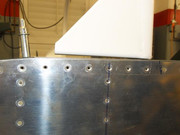
I thought a couple of snaps might help describe what we are talking about.
First off, I'm a first-time builder, this is what I've done.. I sure hope it is correct! I'm currently working on the canopy, so this is unfinished work.
The right angles and straight lines in the pictures look a bit distorted, in real-life the pieces are straight and at 90 deg. where they are supposed to be. In the first picture, you can see the 2 5/8" measurement from the unfilled rivet hole. That is to the back of the roll bar sole plate. The two little lines at the forward position denote the front of the sole plate and the lateral line through the rivet on the canopy deck.
The edge distance from the middle of the forward bolt to the edge of the sole plate is 3/8" and to the lateral line, it is 1/2".
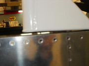
In the second picture, the roll bar looks like it is canted inward, but it is not - the outside edge runs true to the fuselage outside skin (7/32" inboard).
My holes were drilled carefully to avoid nicking the longeron and I had to make the little spacers (underneath) twice. Getting the whole thing together was a chore, I ended up making a stack of spacer, washer, and nut and using a little super glue to hold them together while I slid them forward from the middle of the aft canopy deck.
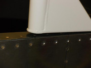
My canopy frame (with the bubble resting on it) slides back and forth pretty easily. It drops down the 45 at the rear and the canopy is just lower than the turtle-deck skin.
I'm keeping my fingers crossed that this will come out right. . .
Hope this helps, Andy!


") .
.
