What's new
Van's Air Force

Don't miss anything! Register now for full access to the definitive RV support community.

Honda 1.8L on RV6A Now Flying!

charosenz

Well Known Member
For those of you who enjoy the building part of this hobby, especially the engine side of things, I thought I would post a link to a short video I made of my "alternative" engine set up.

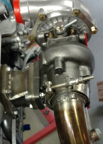
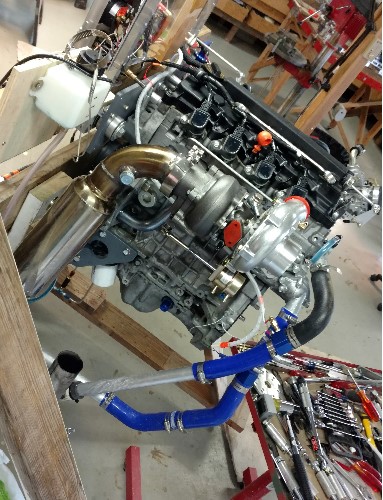
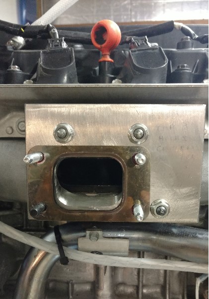
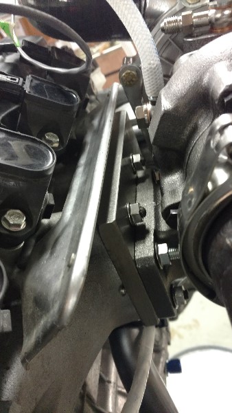
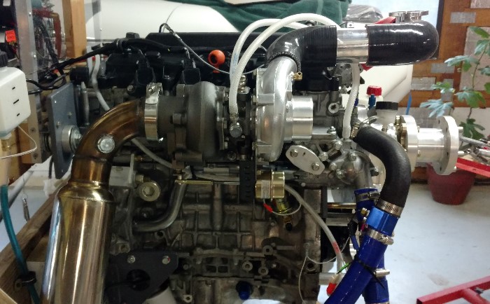
It is Honda R18 Civic engine. 1.8L. This engine is extremely common. It is in current production and has been around for 10 years in various Honda cars. It is a standard port fuel injection and COP Coil on Plug ignition. It has many advanced features like individual oil injected pistons and many other features.

I am also using the Viking Aircraft Engine PSRU (gearbox) and a 68" tapered Warp drive prop. I am very impressed with the Viking gearbox.

One of the features of this set up that I really like is the SDS EFI system. This is a fantastic engine controller. There are over 1500 planes flying with the SDS EFI system. It is a very complete, and flexible, and easy system to install. It manages your fuel injection as well as your ignition system - all easily user programmable.

https://youtu.be/7iHC4tpZxq4

I am not flying with this yet. I have an RV6a airframe done. I will need to build the engine mount and then work on the panel, and other finish work. I have a full time job so who knows when Ill be flying.

Feel free to ask questions.

Charlie Rosenzweig
Longview, Wash.
 
Last edited:
Honda engine

looks like a very interesting project. What sort of horse power do you expect out of it? The SDS system looks very nice.
 
Very interesting indeed. Brings back memories of the CAM100 engine.

Will be even more interesting to see how the Viking gearbox holds up. I hate to say it but I think Jan is still having his customers do his development testing for him. I really hope this isn't the case here.

Don't ya just love how the engine starts and runs so smoothly?
 
Seeing that R18 engine brought back many good memories of tinkering around with the B-series engines of the 90's and 2000's

I still have an old Acura Integra as my beater car, that has a B18A engine in it...with over 357k miles on it.
 
For those of use who are unfamiliar... what's the flight-ready weight and HP of that setup?
 
Does it cruise up on the beefy side of the cam with VTEC fully shifted or are you on the economy side and cruising evonomically? Will you be dependant on a single or dual oxygen sensors? If yes, will you avoid 100LL so your oxygen sensors are not fouled?

I had a tapered, 3 blade Warp Drive ground adjustable on a 125 hp O-290D on a clipped wing Wag Aero Cuby. I was asked to not idle it below 700 rpm as the direct drive impulses were a bit rough on the light prop. It was fine in the 40-130 mph range on that draggy profile. If I needed lower idle I was to go to the four blade, FWIW.
 
Notes below video, on youtube, say 130hp and 300# weight, all up.

I wonder what engine/prop RPMs are at 100%, what they will be at 75% cruise.
 
VNT & Vtec Controller

A set of cams, VNT turbo and a Vtec Controller would be a match made in heaven.
 
Turbo for this engine

A company called Turbo Specialties makes a bolt on Turbo for the Honda r18 engine.

Model: Engine R18 W/T25 Turbo
Part# HC2504E

I wanted to try it on my 2010 Civic EX, but haven't yet pulled the trigger yet. Can increase HP significantly.
 
looks like a very interesting project. What sort of horse power do you expect out of it? The SDS system looks very nice.

The engine in stock configuration is 140 HP at about 6300 WOT.

I show just under 300lbs all up weight including the coolant. But this does not include the radiator.

I do really like the SDS system. WWW.SDSEFI.com
 
Last edited:
Does it cruise up on the beefy side of the cam with VTEC fully shifted or are you on the economy side and cruising evonomically? Will you be dependant on a single or dual oxygen sensors? If yes, will you avoid 100LL so your oxygen sensors are not fouled?

I had a tapered, 3 blade Warp Drive ground adjustable on a 125 hp O-290D on a clipped wing Wag Aero Cuby. I was asked to not idle it below 700 rpm as the direct drive impulses were a bit rough on the light prop. It was fine in the 40-130 mph range on that draggy profile. If I needed lower idle I was to go to the four blade, FWIW.

- The I-VTEC in the "R" series Honda (like this one) is quite a bit different than in all other Hondas. In the R series the I-Vtec is used in economy mode, unlike in the other series where the VTEC is designed to use the performance cams. Many people do not know this. So for this series, all you have to do is disconnect the hydraulic oil control valve to keep it from opening the oil passage that causes the economy cam to be used. To put this another way.....it is defaulted to be in performance mode. Slick deal for this application.

*** Please note the engine is in POWER mode when the oil control valve is energized (and not when it is unplugged as previously stated)- see important update in Post #50 ****
 
Last edited:
Very interesting indeed. Brings back memories of the CAM100 engine.

Will be even more interesting to see how the Viking gearbox holds up. I hate to say it but I think Jan is still having his customers do his development testing for him. I really hope this isn't the case here.

Don't ya just love how the engine starts and runs so smoothly?

Yes, this engine starts and runs like a sewing machine. I am very impressed.

I am very familiar with Jan's past, I began building my RV6a in the late 90s and I have been active in EAA every since.

I am very happy with Jan's support and I am very impressed with this gearbox. Sure, he does improve things as he progresses but I cannot fault him for that.

I am very glad we live in a country where vendors including Vans, Jan and SDS are not so hamstrung with regulations that there is nothing innovative ever brought to the free market. I say - let me decide if I want to accept the risks with experimental aviation airframes, engines and gearboxes.
 
I'm glad to hear you are getting good support from Jan and that you have high confidence in the gearbox, and hope it continues that way.

It will be interesting to watch the rest of your installation evolve. Radiator and radiator placement, exhaust, and whether you stick with normally-aspirated or eventually add a turbo. You certainly got off to a good start by choosing ignition and fuel delivery systems that can adapt to whatever changes you might wish to make as you move forward.

Please do keep posting news of your progress. Frankly, I'm looking forward to watching the video of your first Honda-powered flight! :)
 
Auto engine HP

Notes below video, on youtube, say 130hp and 300# weight, all up.

I wonder what engine/prop RPMs are at 100%, what they will be at 75% cruise.

I wonder what the long term implications will be of using an engine that normally operates generating 25-40 hp (highway driving) and using it at at 50-75% power on a continuous basis. Car engines, even though they can produce high HP, normally do not operate in that HP range for long periods of time. I would'nt think they are designed to be efficient for that range.
 
I wonder what the long term implications will be of using an engine that normally operates generating 25-40 hp (highway driving) and using it at at 50-75% power on a continuous basis. Car engines, even though they can produce high HP, normally do not operate in that HP range for long periods of time. I would'nt think they are designed to be efficient for that range.

That old hangar tale seems to be immortal. While it's true that cars typically operate at those power levels, auto mfgrs actually test the engines at power percentages, conditions, and durations that make the FAA mandated tests for certified engines look like auto highway loads.

If you do honest research, you'll see that the vast majority of 'issues' with auto engine conversions are rooted in the converter. Poor cooling design in the a/c. Poor engine to propeller interface (adapter, gear drive, torsional damper, etc). Poor design of the (modified) intake and exhaust systems. Thinking you can take an engine rated at 'X' HP in a car and run it at 1.5*'X' HP in a plane. Etc, etc, etc.

There are thousands of auto conversions flying successfully; we just don't see a lot of info on forums like this one for what should be obvious reasons.

Charlie
 
I wonder what the long term implications will be of using an engine that normally operates generating 25-40 hp (highway driving) and using it at at 50-75% power on a continuous basis. Car engines, even though they can produce high HP, normally do not operate in that HP range for long periods of time. I would'nt think they are designed to be efficient for that range.

Perhaps you don't realize that modern auto engines are run at WOT for hundreds of hours during validation and are designed to be efficient at all ranges.

Watch this video: https://www.youtube.com/watch?v=8tEqwXrqzH4

All the auto OEMS do similar tests.

Here is my friend Russell Sherwood's 2017 SARL record with his Subaru powered Glasair. The last race was run at 5250 rpm with a bone stock engine:

Texoma Air Race - 145 mile closed circuit - Average speed 250.94 MPH
BCAF Air Race - 159 mile closed circuit - Average speed 252.95 MPH
Hardin Air Race - 135 mile closed circuit - Average speed 251.92 MPH
Big Muddy Air Race - 137 mile closed circuit - Average speed 254.77 MPH
Indy Air Race - 133 mile closed circuit - Average speed 256.66 MPH
Ghost Run Air Race - 155 mile closed circuit - Average speed 256.91 MPH
Rocket Air Race - 159 mile closed circuit - Average speed 261.60 MPH
 
Last edited:
As the guy that ran those life tests for Chrysler in a former life...I have to wonder where some of you get your information. I can assure you there are no engine torture tests run on an auto engine to simulate life in an aircraft. There are no G-loading tests positive or negative and you can rest well assured the engine is not designed for G in any manner whatsoever. There are no altitude or temperature ramps in life testing that even loosely resemble a standard descent let alone anything sporty. The exhaust and intakes are identical to the production vehicle in those tests (both of which throttle performance)...will you be running the same? The engine electronics have a LOT to do with reliability...which airplane guys tend to scrap right off the bat (and it took us hundreds of hours to get those timing/fuel maps right).

We abused the Viper’s motor horribly in life testing but to compare auto testing to aircraft life is frankly laughable. I could go on for hours but you get the idea. We could test for months, then put the engine on the track and it would grenade inside 50 laps. Porsche had a fantastic test procedure/life test back when Dr Ferdinand ran the show but since his death even they have fallen (the 996 lacking oil pan baffles etc). My point being, a lab test is a decent start but it has to simulate what you’re intending to see and some things can’t be tested in the lab. Nothing of what an airplane sees is tested in an auto torture test...nor can it be.

By all means experiment. That’s what this part of aviation is for and I encourage any who are so inclined to do so. But do not believe even half of what a company selling auto conversion parts tells you as it pertains to engine testing done by the big 3 and for Gods sake do not put a lot of faith in a commercial posted on YouTube.

What part of the FAA engine certification tests are not exceeded by the auto OEMs today? What part of aircraft use is harder than what auto engines see in validation testing?

Maybe you never had one of these at Dodge? Developed for the Corvette program because they were blowing up on the test track due to G loads taking the oil away from the pickup: https://www.youtube.com/watch?v=LvVK6neQ4q4&index=32&list=FLiyBZlgDHg2GvQfelECCGoQ&t=0s

And, I don't think you watched the first video link I posted either. Think a Lycoming would last this long putting out 625hp (same specific output as the 3.5L Ecoboost)? How about passing the cold coolant test? This was a test out of the dyno room for the last half. You don't think the Baja race was a little more severe than the FAA requires? A Lyc is putting out 30hp/L, should be easy to make it last at 2700 rpm. This engine puts out 104hp/L- a MUCH more difficult task to achieve this kind of longevity.

And you're forgetting that there are thousands of auto engines flying and working just fine and have been for decades.

Tell us why an auto engine and proper gearbox won't work in an aircraft application?

The FAA aircraft engine certification test requirements are here: https://www.ecfr.gov/cgi-bin/text-i...0&mc=true&node=pt14.1.33&rgn=div5#sp14.1.33.d

These are far short of what the auto OEMS require to pass an engine for production.

I specifically posted the SARL results for people who dismiss the ability of auto engines to work and last in aircraft. Russell passed 600 hours on it last year. The engine was used when he installed it and it's never been opened up. He has over 20 SARL class wins and some overall wins.

A lot has changed in the last 20 years in the auto industry, well maybe not at some of the big 3...

Kia engine testing https://www.youtube.com/watch?v=GNPB3RtHN2M 300 hours at full rated power and them some more above redline.

AMG: https://www.youtube.com/watch?v=cSPM1KxONAk

GM: http://media.chevrolet.com/content/...5/Fact Sheet 3 - Durabilty and Validation.doc

The Ford vid certainly has a big marketing angle but I doubt that they faked the whole set of tests.

Why don't we all let Charlie continue his testing here and see how it works out? I know I'm interested.

"People Who Say It Cannot Be Done Should Not Interrupt Those Who Are Doing It"
 
Last edited:
As the O.P. I would like to respectfully ask that those who simply want to debate whether certified engines are better than non-certified engines to please start their own thread. I will join you over there.

I do not want to lose people who are interested in what I am doing

I welcome others to ask questions and share their ideas and projects that are similar.

Whether you want to fly an experimental airframe, with or without an experimental engine - more power :) to you!

I will continue to post updates and information on my project, as long as there is interest.

I do plan to do some testing with a turbocharger because I think it makes a lot of sense especially for this engine, on this airframe. This engine is unique in that it has a integral (read internal) exhaust "manifold" that results in a single exhaust opening. This saves weight, space and of course makes for a very easy turbo installation.

I will post pictures later this weekend, at least of the exhaust port and stainless adapter with the T-25 flange profile.

Right now I am using different pitch settings on my prop to find the best pitch for max power. I love how easy the warp drive prop is to change pitch. I have only taken it up to 5000 rpm and had to stop there as the torque started to rotate the whole engine stand. It is very stout, built with 2x6" and it is 4 feet wide, but it is on wheels so I can easily roll it in and out of the shop to run. I have built an "out-rigger" on it so it will be more stable at higher RPM......

Charlie
 
Last edited:
Keep up the good work Charlie and if you'd like some help in matching a turbo, I'd be happy to help.

Let's try to keep this thread on topic and positive please.
 
Last edited:
Keep up the good work Charlie and if you'd like some help in matching a turbo, I'd be happy to help.

Let's try to keep this thread on topic and positive please.
P

Ross

Thanks.

I want to be concervative and keep pressure and heat reasonably low.

With the unique issue of the Pressure Ratio being higher at altitude I am leaning on a slightly higher capacity compressor than what I would use for a car on the ground.

Based on my early calculations I am looking at a max flow of about 18 lbs/min and P.R. at altitude of 2.0 (40"/20"). Hence the engine will only "see" 5lbs of boost.

That being said, I like the looks of a 28 turbine and a 60 compressor with an A/R on the turbine side somewhere .62 or higher.

Thoughts?
 
Just a brief comment about adjusting your Warp Drive prop. The manufacturer's instructions are pretty good when it comes to telling you how to adjust it, but they could be better. I discovered this when setting the 3-blade Warp prop on my "other" airplane. These discoveries ultimately yielded much smoother operation.

Tip 1) When adjusting prop pitch, do it for all 3 blades at exactly the same rotational angle. Achieve this goal by pulling your spark plugs so you can easily turn the engine. Rotate the prop so the leading edge of Blade 1 is horizontal as measured with a 24" carpenter's level or similar (I used a digital level). Now adjust your blade pitch as necessary. Repeat for Blade 2 and Blade 3. In our case I make the adjustments with the prop blade at the 3 o'clock position, as viewed from the cockpit. Each blade is adjusted only after it has been rotated to the 3 o'clock position.

Tip 2) If using Warp's prop protractor, you will notice the bubble is narrower than the space between the two lines printed on the spirit level vial. This is a source of inaccuracy. Always set your pitch with one end of the bubble directly beneath one of the lubber lines. Doesn't matter which one - pick one and stick with it. This will remove the tiny bit of guesswork that goes on when we are trying to center the bubble between the two lines. Peg the bubble up against a line and there's no guesswork.

By following these two tips the net effect on prop blade pitch will be small, but on our aircraft it made a noticeable improvement in "buzz" coming back into the cockpit. The Warp prop protractor is a great tool. Using these two tips makes it work even better.
 
Last edited:
P

Ross

Thanks.

I want to be concervative and keep pressure and heat reasonably low.

With the unique issue of the Pressure Ratio being higher at altitude I am leaning on a slightly higher capacity compressor than what I would use for a car on the ground.

Based on my early calculations I am looking at a max flow of about 18 lbs/min and P.R. at altitude of 2.0 (40"/20"). Hence the engine will only "see" 5lbs of boost.

That being said, I like the looks of a 28 turbine and a 60 compressor with an A/R on the turbine side somewhere .62 or higher.

Thoughts?

What altitude and hp are trying to match for? I'll run some calcs and see what I come up with. Typically we run very loose turbine housings and very large turbines for aircraft applications. Wanna run ball or journal bearings?
 
Just a brief comment about adjusting your Warp Drive prop. The manufacturer's instructions are pretty good when it comes to telling you how to adjust it, but they could be better. I discovered this when setting the 3-blade Warp prop on my "other" airplane. These discoveries ultimately yielded much smoother operation.

Tip 1) When adjusting prop pitch, do it for all 3 blades at exactly the same rotational angle. Achieve this goal by pulling your spark plugs so you can easily turn the engine. Rotate the prop so the leading edge of Blade 1 is horizontal as measured with a 24" carpenter's level or similar (I used a digital level). Now adjust your blade pitch as necessary. Repeat for Blade 2 and Blade 3. In our case I make the adjustments with the prop blade at the 3 o'clock position, as viewed from the cockpit. Each blade is adjusted only after it has been rotated to the 3 o'clock position.

Tip 2) If using Warp's prop protractor, you will notice the bubble is narrower than the space between the two lines printed on the spirit level vial. This is a source of inaccuracy. Always set your pitch with one end of the bubble directly beneath one of the lubber lines. Doesn't matter which one - pick one and stick with it. This will remove the tiny bit of guesswork that goes on when we are trying to center the bubble between the two lines. Peg the bubble up against a line and there's no guesswork.

By following these two tips the net effect on prop blade pitch will be small, but on our aircraft it made a noticeable improvement in "buzz" coming back into the cockpit. The Warp prop protractor is a great tool. Using these two tips makes it work even better.

You pretty much described what I do as well. I also use a digital pitch angle gauge that goes down to a tenth of a degree. Works great.
 
What altitude and hp are trying to match for? I'll run some calcs and see what I come up with. Typically we run very loose turbine housings and very large turbines for aircraft applications. Wanna run ball or journal bearings?

I am targeting 5 lbs at 10,000 feet, which is what I meant when describing the 2.0 pressure ration where by I would be using roughly 40" MAP, with roughly a 20" pressure outside air.

Since I am not needing a quick spool and relatively low boost at 5lbs over "normal" 1 bar, I am absolutly fine with a journal bearing. It will be a oil and water CHRA.

Let me know what numbers you come up with. My calcs come up with 18lbs/min with less than 1.5 P.R. at sea level and 2.0 at 10k feet.

Charlie.
 
My calcs show around 32 lbs./min. for 175hp at 10,000 feet and 40 inches.

I'd use pretty much the same compressor size as on my RV and probably around a .62 a/r turbine housing.
 
exhaust down pipe and internal exhaust "manifold"

Here is a link to a picture of my exhaust. Notice the internal (integral) exhaust manifold - with only a single exhaust outlet. Great. I welded up a stainless steel exhaust adapter to the honda bolt pattern with a T-25 turbo flange bolt pattern on the exit flange.

I do not have the turbo on it yet. I am still debating on the one to use.

Notice the dual O2 weld bungs. I am using a wide band meter which is very accurate and the nice part is that it also has an aux output that the SDS EFI comuter takes so I can see my A/R in both the WB meter and the SDS display.

I also have a EGT temp probe in the back of the down pipe out of view which is why you see the band clamp just above the O2 sensor.

Also notice the oil temp sender with capped AN fitting ready to supply turbo oil and the blue AN fitting on the pan for the turbo oil return.

https://lh3.googleusercontent.com/o...2S_eGdazdOmTdBs7SwesHJGG4dMFqE3E=w359-h637-no

Hope this photo comes out. First time posting a google photo link to this forum....

Charlie
 
My calcs show around 32 lbs./min. for 175hp at 10,000 feet and 40 inches.

I'd use pretty much the same compressor size as on my RV and probably around a .62 a/r turbine housing.


Ross, what set up are you using? What trim on the compressor and A/R and Trim on the turbine side? What MAP do you use at 10k?

Here are the numbers I am ran lately. The are calculated with 10lb boost, even thought I only plan to use 5-7lbs - at sea level. But I ran it with 10 lbs to get me the performance of the turbo at 10k altitude where it will be 40" (10lbs) over 20"....

http://cybrina.mooo.com:8080/WebMod...oost=10&maxrpm=5500&rpmstep=500&Submit=Submit

This suggests 18lbs/min. I ran a completely different calculator and got the same results.....

Charlie
 
Last edited:
Ross, what set up are you using? What trim on the compressor and A/R and Trim on the turbine side? What MAP do you use at 10k?

Here are the numbers I am ran lately. The are calculated with 10lb boost, even thought I only plan to use 5-7lbs - at sea level. But I ran it with 10 lbs to get me the performance of the turbo at 10k altitude where it will be 40" (10lbs) over 20"....

http://cybrina.mooo.com:8080/WebMod...oost=10&maxrpm=5500&rpmstep=500&Submit=Submit

This suggests 18lbs/min. I ran a completely different calculator and got the same results.....

Charlie

Ross, d
* UPDATE *

I found a different calculator on line (Matchbot) by Borgwarner, and this time ran the numbers that included a variable for altitude, and I see the reference to 30+ lbs/min that you mentioned.

Here is a link to what I came up with .

http://www.turbos.bwauto.com/afterm...wts=400&pt6_wd=83&pt6_wd2=74&pt6_wrsin=92044&

I also noted that there were two different numbers as it relates to lbs/min. It shows about 30+ lbs/min on the comperssor side, but only about 19 lbs / min on the turbine side.

would you agree with this? and what you see on the link?

I am still interested in the details of your real life experience with the turbo set up on your RV6a - especially considering you have almost 500 hours on it...I know other readers would like to know as well...

Charlie.
 
I'm using a TO4E-50 compressor and T3, stage 3 turbine wheel in a .82 housing. We've used this on a couple of RV turbos with 160-225hp and it's a good match. With your 1800cc, I'd drop down on the turbine a/r to .63 but a similar sized compressor would be needed at 175hp.

Most people match turbos wrong and many spreadsheets are wrong too as they don't take density ratio into account at airplane altitudes. People blindly follow what others have done before them, not knowing enough to realize the errors.

Compressor inlet flow must be much higher at 10K to deliver the required mass flow at the 2.0 pressure ratio.

My compressor discharge temps confirm we're operating on the map where we should be.

I would not use a turbine wheel smaller than 2 inch exducer (minor diameter). Not sure if you can do that with T25 type flanges. Haven't checked what you can get in the GT series turbos but you may have to mix and match turbo frame parts to get a proper match of turbine and compressor like I did.
 
Last edited:
I'm using a TO4E-50 compressor and T3, stage 3 turbine while in a .82 housing. We've used this on a couple of RV turbos with 160-225hp and it's a good match. With your 1800cc, I'd drop down on the turbine a/r to .63 but a similar sized compressor would be needed at 175hp.

Most people match turbos wrong and many spreadsheets are wrong too as they don't take density ratio into account at airplane altitudes. People blindly follow what others have done before them, not knowing enough to realize the errors.

Compressor inlet flow must be much higher at 10K to deliver the required mass flow at the 2.0 pressure ratio.

My compressor discharge temps confirm we're operating on the map where we should be.

I would not use a turbine wheel smaller than 2 inch exducer (minor diameter). Not sure if you can do that with T25 type flanges. Haven't checked what you can get in the GT series turbos but you may have to mix and match turbo frame parts to get a proper match of turbine and compressor like I did.

Ross,

That is very good information and I appreciate you sharing that. I am looking to for less HP. I think 180HP is a good safe number to shoot for with this engine. Plenty for what I am looking for.

You are certainly welcome to post pics of your turbo set up in this thread if you have time, I would like to see it and I suspect so would other readers.....but I know you are quite busy.....

Yes, calculators are what they are. The Matchbot calc is good and bad. Good because it is one of the few calculators that incorporate the changes in altitude for different set ups. But it is biased in that it automatically inserts boost based on the particular BW turbo it thinks you need - which may or may not really be the boost you are looking for. (like in my last link).

I am not sure if you had a chance to look at the pic of my exhaust set up, but I am not opposed to welding up a honda to T3 flange adapter like the Honda to T25 flange that is shown....

The next step in my set up is to do some accurate fuel consumption measurements at WOT to calibrate the FF# setting in the programmer.

Charlie.
 
Many calculators also underestimate engine mass flow by using unrealistic or arbitrary VE values. I base mine on hp which is overall more accurate.

Even a lot of the Reno Sport Class folks are doing it wrong IMO.

The T3 flange will open up some larger matching turbines for you. There is no sense in having a tiny turbine wheel on an application which is not at low rpms, is usually at high load and does not demand fast response. It's very different from automotive in that respect. The larger wheel is much more efficient here than a small one and should give better BSFCs everywhere and more power with less manifold pressure.


Here's a shot of my intercooler. The turbo is buried aft of the engine, I'll try to dig up a photo from the top. That might take a bit, we're working 7 days a week right now to keep up with orders. It's snowing again here anyway. Might as well be at work...

If you're running down around 135hp in cruise, be sure to look at the surge margins up high at the lower pressure ratios. The TO4E-50 compressor has a very wide operating range which works well in my case. It's a great match at low power and high and high and low altitudes too.
 
Last edited:
Here are a couple pix of the same turbo on an STi engine in an RV7.


My turbo is high mounted to avoid the use of the scavenge pump required on this installation.

We're both using the integral wastegate with a dual port actuator so we can easily change the manifold pressure from the cockpit.

Notice the strong mount to support the turbo here which is critical to reliability. Also consider exhaust slip joints to reduce mechanical loads on the exhaust pipes from differential expansion. I'd use 321 stainless for all the piping to the turbo, much more reliable than 304 at these temperatures.
 
Last edited:
Ross,

That looks great. A lot going on in that ship! Thanks for sharing.

I have SS on order to weld up a new Honda to T3 flange adapter.

and I am glad that I only have one exhaust to work with..

Charlie


Here is a pic of the "first fit" of my new T3T4 on the R18. The short adapter I welded up will work well for the test stand, but I will need to reduce the size of this to make it fit inside the Rv6A cowling.

Here is the side view.


It will be a few weekends before it is back up and running.

I am not sure why I am only getting links and not actual photos. I have followed the instructions to have photos appear but sorry, only links. If anyone has some insight on this please share...

Charlie
 
Last edited:


Here is a pic of the "first fit" of my new T3T4 on the R18. The short adapter I welded up will work well for the test stand, but I will need to reduce the size of this to make it fit inside the Rv6A cowling.

Here is the side view.


It will be a few weekends before it is back up and running.

I am not sure why I am only getting links and not actual photos. I have followed the instructions to have photos appear but sorry, only links. If anyone has some insight on this please share...

Charlie

One more attempt at the photo download....

AF1QipNgrjQh3V9XBxFtb5OScyZCdXnecnZdhwhApsGp


This one using google photos and not MS onedrive.....The URL is pasted in the post but no photo...weird....

AF1QipNgrjQh3V9XBxFtb5OScyZCdXnecnZdhwhApsGp
 
Last edited:
Testing....

Thanks Snowflake, here are a few pics using halie.com

Top view of first fit of T3T4

This is resized down to 500 kb hope it works.

ou4.jpg


Here is the side view.

ouQ.jpg
 
Last edited:
A company called Turbo Specialties makes a bolt on Turbo for the Honda r18 engine.

Model: Engine R18 W/T25 Turbo
Part# HC2504E

I wanted to try it on my 2010 Civic EX, but haven't yet pulled the trigger yet. Can increase HP significantly.

Yes, they do have a kit for the Honda Civic with the R18 engine.

In fact here is a screen shot that shows the Tq/HP graph for one of their R18 turbo projects.

out.jpg


Here is a good article too...

https://www.turbokits.com/Honda/Civic/Turbo_Kits/TSI_Extreme_Turbo_Kit/274/

Here is a good article from supersstreet magazine....

http://www.superstreetonline.com/how-to/engine/htup-1010-2006-honda-civic-ex/

Probably the one company that has the most info products to Turbo the Honda R18 engine is fullrace.com

https://www.full-race.com/articles/civic-r18-turbo-kit-faq/

Here is a screen shot from the fullrace info page that does a great job of explaining why it makes sense to turbo a Honda R18 engine.

oub.jpg


Also on a side note it is worth noting that when you see negative comments about the R18 it is almost always traced back to the fact that the civic transmission and clutch do not hold up well with boost past 7lbs....but rarely have I ever read about issues with the engine....
 
Last edited:
New T3 Mount with custom adapter plate

Here is the new custom adapter plate I made out of 1/2" stainless. The outer bolts are Honda. The inner bolt patter is T3. Notice the lower left bolt is a "companion" bolt serves to hold the adapter plate and the T3 at the same time. The other 3 T3 bolts are tapped to receive 8mm x 1.25 studs. Tapping the 1/2" stainless was fun. That is a whole topic by itself.

ouF.jpg
 
T3 installed with view behind to see adapter flange

Here you can see the flange installed that allows the T3 to mount upclose and tight to the integral Honda exhaust outlet.

ouJ.jpg
 
T3 installed with new 1/3" adapter flange

Here you can see a test fit of the T3 on the new adapter flange. This is just a test fit with most of lines not installed or tightened up yet.

The routing of the T3 over to the Throttle Body is also a test fit and will be used for run-ups on the test stand but will be re-routed once installed in the plane.

oup.jpg
 
New Video of T3 Turbo mounted and engine run up

Here is a link of my most recent update. I created a new exhaust flange adapter that reduces the offset of the turbo. This new adapter is simply a piece of 1/2" stainless steel that has both the Honda bolt pattern as well as the T3 turbo bolt pattern.

This short run up is with the T3/T4 turbo with the new flange but does not include the prop - yet. That will be next.

https://www.youtube.com/watch?v=0P_w1bQq5Uo

You will notice virtually no Manifold Pressure which is due to no real "load" on the engine.

Charlie
 
short video of i-VTEC valve movement on and off

Here is a link of the i-VTEC intake valves operating both with and without the i-VTEC spool valve activated. It happens quick so watch close.

https://www.youtube.com/watch?v=sVE_4JoDytA

In the video you will see that the intake valves operate independently when the oil control valve is not energized. This is when one of the valves is using the economy profile cam lobe, and the other on the performance profile lobe. When the spool valve is turned on, the valves move in unison - this is when both valves are locked together and they are using the performance profile cam lobe.

Most have heard about the VTEC systems that Honda has used over the years. In most applications in the past the VTEC added extra performance when it "kicked in". This is not the case on the R18 and R20 engines like I am using. In this series it is actually the opposite. In this series of engines they actually go in to "economy mode" when the ECU senses low load, and otherwise it is in "performance mode".

So why go in to this much detail? You do not want this engine operating in economy mode for aviation use. How do I know? Because prior to learning this much about the system, I was advised some misinformation about the i-VTEC and I unknowingly ran it in the economy mode while under load on my test stand and I lost compression in two cylinders. While I cannot say for sure the true cause and effect because I have not done a teardown, I suspected it just ran too hot, even though I was keeping it at 13:1 A/F ratio.

The good news is that I picked up a 2015 engine with 13k on it for only $550, and was able to swap it in the test stand over the weekend.

I will post what I learn on the tear down...keeping and open mind that the cause may be unrelated but I wanted to share this so others may learn from my experiences.
 
Last edited:
We've had a couple customers with the Honda V6 VTEC engines in their T51s do some testing on activating the VTEC through the SDS controller. They can perceive almost no change in power/ speed at their typical 4500-5000 rpm operational flight ranges.

It will be interesting to see what you find at different rpms on your stand with the new engine.
 
inrt

We've had a couple customers with the Honda V6 VTEC engines in their T51s do some testing on activating the VTEC through the SDS controller. They can perceive almost no change in power/ speed at their typical 4500-5000 rpm operational flight ranges.

It will be interesting to see what you find at different rpms on your stand with the new engine.

Ross, Good to know thanks for sharing.

I cannot say that I am surprised to hear this. There are a lot of variables to consider. At least for the R18 and R20 series, the iVTEC was only a tool to try to get good economy.

I can put a digital scale on a tether to measure the pull of the engine on the test stand since I have my test stand on small wheels, but I am not convinced it yields real accurate data. There is a fair amount of rolling resistance with this set up.

I plan to eventually have the spool valve on a switch just to see what happens with it switched on and off and watch the tension, as well as the EGT temps and MAP. But regardless I just cannot see any value in having it use the economy mode at all in an aviation application.

Now if I could only prevent my day job from interfering with this hobby!

Charlie
 
Just a brief comment about adjusting your Warp Drive prop. The manufacturer's instructions are pretty good when it comes to telling you how to adjust it, but they could be better. I discovered this when setting the 3-blade Warp prop on my "other" airplane. These discoveries ultimately yielded much smoother operation.

Tip 1) When adjusting prop pitch, do it for all 3 blades at exactly the same rotational angle. Achieve this goal by pulling your spark plugs so you can easily turn the engine. Rotate the prop so the leading edge of Blade 1 is horizontal as measured with a 24" carpenter's level or similar (I used a digital level). Now adjust your blade pitch as necessary. Repeat for Blade 2 and Blade 3. In our case I make the adjustments with the prop blade at the 3 o'clock position, as viewed from the cockpit. Each blade is adjusted only after it has been rotated to the 3 o'clock position.

Tip 2) If using Warp's prop protractor, you will notice the bubble is narrower than the space between the two lines printed on the spirit level vial. This is a source of inaccuracy. Always set your pitch with one end of the bubble directly beneath one of the lubber lines. Doesn't matter which one - pick one and stick with it. This will remove the tiny bit of guesswork that goes on when we are trying to center the bubble between the two lines. Peg the bubble up against a line and there's no guesswork.

By following these two tips the net effect on prop blade pitch will be small, but on our aircraft it made a noticeable improvement in "buzz" coming back into the cockpit. The Warp prop protractor is a great tool. Using these two tips makes it work even better.

Thanks for this tip. The idea related to the bubble alignment wss one i had not heard. I will have to pull my spinner shortly and while I'm at it I'm going to double check my prop using the bubble to the edge technique. Thanks again this totally makes sense
 
Update on project new details with video on VTEC

It has been awhile since I posted. I experience a loss of compression in #2 and #3. But I am back up and running with everything looking real good.

I suspect the loss of compression was a two fold. 1) I got some misinformation on how to know when the engine was using the "economy" cam lobe as well as my fault for running it too lean (13.0 to 13.5 A/F) under load.

Fortunately these engines are so plentiful it was a quick trip to a large auto recycler to get a 1 year old engine with only 13k miles for only $600.

I could not hardly justify the time and money for a repair at those prices.

The way to be 100% sure when both cams were using the "power" lobe cam and not the "economy" lobe was to video the intake rocker arm action with the oil pressure over 40 psi. Much to my surprise it is NOT when the oil control spool valve was off (not powered). Which is not what I had been advised.

Here is a link to the very short video I took. You have to watch real close in order to see both intake valves move independently for a 2 rotations before I power up the oil spool valve and once it is powered, you will see both intake rocker arms begin to work in unison. This is the indication they are both using the "power" lobe on the cam.

Here is a link.

https://www.youtube.com/watch?v=sVE_4JoDytA

Let me know if you have questions.

Charlie
 
Back
Top