johnny stick
Well Known Member
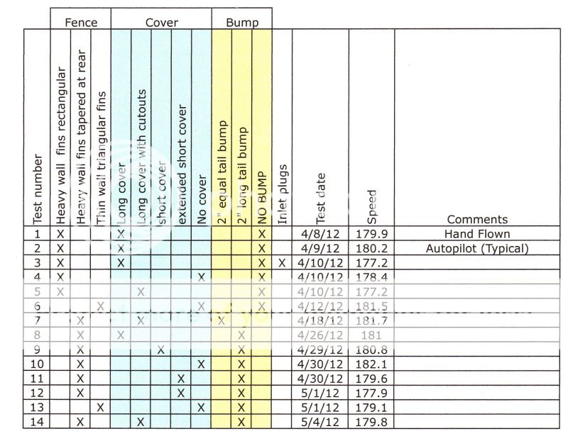
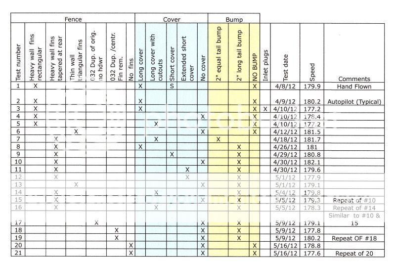
Bob, thanks for presenting your results to date in a chart form, this is good stuff.


Bob,
Have you ever tested the exact same configuration multiple times on different days to see how much scatter there is in the results?
I'm betting you would find a kt or two of scatter, which means that perhaps you need more than one test point on one flight to decide whether a change has given a small speed increase or not.
Why not fly a couple more tests on different days with your current configuration?
Bob,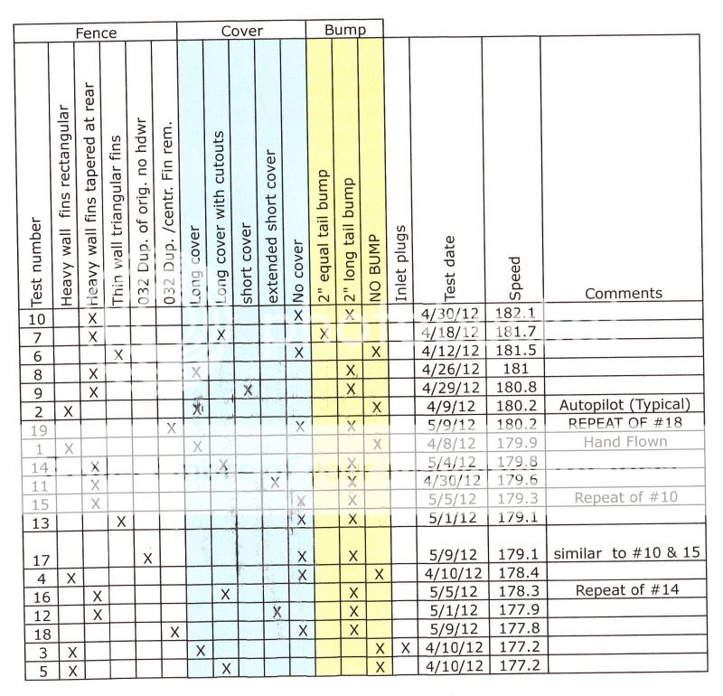
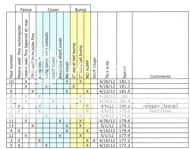
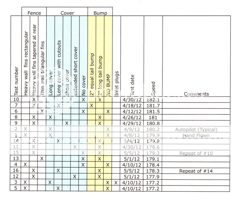
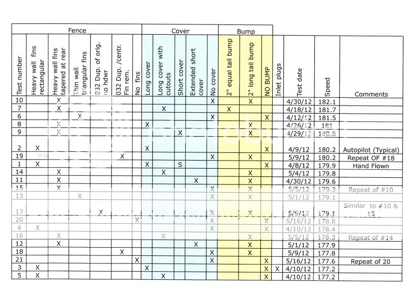
With the test rsults sorted by speed I think I have a better direction for the next step:
It has been apparent to me over the last few days that I am not dealing with a single variable even when I change only one variable. I agree with your observations and conclusion.
All I got done yesterday was pull the parts off to replace the three vertical elements. Will try to do more today. I am trying to force myself to exercise properly for my health. I have been working until 3 am many nights until I was too tired to exercise so yesterday I switched priorities and you can imagine the result.
I also deleted some of the obsolete tables from photobucket and learned not to do that again. It effects the thread here in a couple of ways. The images are linked and not really resident here so when they are deleted from there they are deleted from here also. There is usually a notice posted here so there is some awareness. However, I found one image that was not in this thread before so at least under some conditions the link can be associated with the wrong image. In the case I saw it was a different subject all together (a magazine cover) but some different image re-links could go undetected and provide incorrect information. I will not do that again. Well it's afternoon and I haven't exercised so I had better get at it or I will not get the change for retest done today either.
Bob Axsom
")
Bob,
I am getting an error message on your images stating they have been moved. Any thing you can look into?
....... of wonder if 180 - 181 KTAS at 6000 DA corrected for temps is as fast as my stock IO 360 can make my particular -6 go?????........
I should be able to run down that #71, but still trying to figure out the methodology. 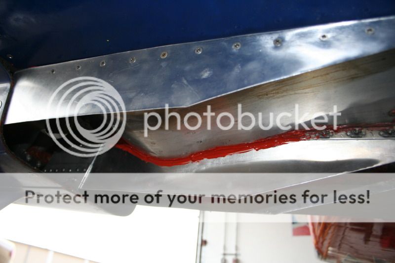
...Recently a smart aero guy whispered in my ear that reducing the stock -6 exit to about 1/2 the normal area, and adding a cowl flap for climb may be as effective as all the fence/afterbody work...
...what kind of pressures have you noted in the upper plenum? At 180Kt I am seeing 14.7in H2O. At 180 kt the pitot pressure should be around 21.5 in h2o.
. What is your altitude when you're measuring 14.7"?I have the low side of the sensor tied to my aircraft static port and the high side to a static port (1/8 tube with .040 holes drilled on 4 sides) at the fuel distribution block.
Should there be this great of a loss? If I understand, if there were perfect pressure recovery I should get the same pressure as a pitot tube?
If the nose strut is in the way for proper outlet placement, or function, why not move the outlet?
Statement overheard at Reno:
"I've never seen an idea so good that I couldn't copy it!"
Look where Lancair put the outlets on the go-fast Legacy. There is science behind that placement (on the bottom, near the outer corner) - might as well give it a shot! Might take some exh system re-configuring? Won't work on the skinny tandem airframes...
Using Dan's idea of a replaceable outlet section, it would be easy to experiment. Are ya listenin', Super Bob?
Carry on!
Mark
Bob, I see now how your non-standard exit changes from the standard.
By all means, forward my prototype to where ever it might do the most good (or harm!?!?). I remain convinced that just streamlining the exit air has significant benefit, both for cooling efficiency and drag reduction.
Right now I am kinda freezing my design. I have some ideas about where to go, but I am wondering about the benefit at this point. It seems that I am stuck on a plateau.
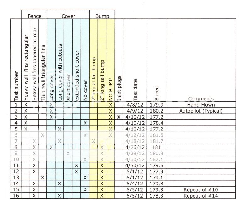
Multiple 3 leg NTPS speed runs without configuration changes on different days with the same method yield results +/- 1.5 knots.
I recently closed my elevator ends with no apparent speed increase (maybe a decrease). I kind of wonder if 180 - 181 KTAS at 6000 DA corrected for temps is as fast as my stock IO 360 can make my particular -6 go?????
Waiting for my first SARL opportunity (Indy) to see what happens.
I previously posted a video on tuft testing using a cowl flap. The testing revealed poor airflow across the flap when closed.
Makes me wonder how it will work with a smoothing after body ala Veterman in conjunction with the movable flap.
I want to focus on the magic 7 degree number blending back into the bottom fuselage. The idea is close off excess exit area, smooth the flow over the cowl flap between the stacks, increase the flow around the exhaust pipes to better match exterior flow.
Then added my gen two Vetterman fairing and life was good and faster also.
Bingo. Reducing the exit area and the frontal area of the cowl is the secret to success, however....
As pressure in the lower cowl increases due to the reduced outlet area, air will tend to leak in other areas. Around the prop spinner is one, and any gaps in the hinges/platenuts/camlocks as well. Tightly sealing the cowling and making all of the cooling air exit the bottom will be the challenge. A good way to test this is to tape the cowling joints all around and measure cht and airspeed.
Around the spinner, Tom Martin's method seems to work... but his results actually reduced airspeed due to increased mass airflow... so the reduction in outlet area is necessary to regain speed.
Bottom line... reduce cowl exit area, seal the cowl air leaks and reduce cowl frontal area. 100% money-back guarantee to increase speed.
Get me faster.......then we'll work on fine tuning Aurora is my next step.
Ahhh! Bob, what have you done!?!
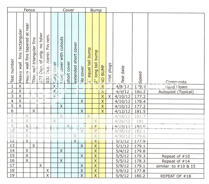
Once this test is done (basically to see how much the cover mounting hardware affected speed) I think I will try a couple of changes on the fin profiles.
Bob Axsom
Test #18 achieved 177.8 kts - pretty bad and I had time left so I flew the triangle again and got higher speeds on every leg and ended up with 180.2 Using Kent's 180 good/bad split logic this one is still barely in the game. I will update the tables and think about what to do next.
Bob Axsom
Bob - The fact that you can fly the same configuration twice and get speeds that are 2-3 kt different suggests your current test technique produces results that are only accurate to 3 kt or more. The changes your are making to the aircraft probably have an effect on performance that is smaller than the accuracy of your test. It is useless to try to compare results from single data points given the demonstrated test to test variability. If you wish to determine whether any given mod helps or hurts you'll need to get a test protocol that yeilds higher accuracy.
Given the level of accuracy you need to measure, you need to fly several tests on each configuration and average the results. Given that there can be small effects from rising and descending air mass, you should do these tests on several different days.
Do you have the ability to record engine and flight data for later processing? What test protocol do you use? It might be possible to tweak the test protocol somewhat to reduce the test to test variablity.
All good info Vern! I did not know Tom lost speed when he closed down the cowl on the prop hub. I knew he no longer had to open his cowl flap for climb, so it makes sense. Glad you mentioned it here, as that would have been disappointing to seal there and slow down...until the light bulb came on. Will plan those mods together, in sequence. I discovered that with my new Van's spinner and my extended hub, I can't use Tom's method, as the forward edge of the cowl won't close on the round part of the hub. Will be using Dan's method instead.
Hey Dan, have you measured the effect (temps and speed) of the baffle material closures you use at the hub? I know you built it that way, but given Vern's comments, I wonder if there is an optimum blend of sealed prop hub and exit area...perhaps its just that the seals allow you to go smaller and smaller, and gain speed via mass airflow reduction, until you reach your EGT CHT comfort limits. Thoughts?
I added the baffle material like Dan's before the Texoma race. Prior to this mod my small oil leaks under the front of the engine migrated forward. After adding the prop seal the oil moves rearward. Makes sense. I also noticed my CHT's increased about 15 degrees which does not agree with Tom's result. Did not see an obvious speed change but I did not run the triangle course either. It appears a significant amount of air from the lower cowling was exiting between the cowl/spinner gap on my RV8.
Bob Mills - It will be interesting to see how you decide to modify your exhaust. I chose the 4-1 and extended the collector with the intention of reducing the cowl outlet. Still trying to decide if I go the bluff body route or not. Not enough time for me to try lots of options so the result is no action.
On a side note I would like to see the T-6 class at Reno go away and see a 4 cylinder RV only class added. RV's are not competitive in any Reno class (not talking about Super RV's here).
)On the day of the test for the prop seal baffle, was the OAT hotter, or did you do that test with a heat-soaked engine (second, third flight on a hot day)? All that could raise oil temps and CHT and give an apples to oranges comparison. Kevin is spot on on the multiple test profile. When I'm really in the test mode, I try to do them on multiple days and, if its a reversible mod, do them in opposite order (A first on one day, B first on the next...hoping for similar conditions...which can be the hard part).
Dan, if you're still reading this thread, have you measured an impact to performance from the measuring devices?

All that could raise oil temps and CHT and give an apples to oranges comparison.
OAT 60
exit air 140
cht 340
(140 - 60) / (340 - 60) = 28.5
Does my plane suck or what?
I think that this approach intuitively looks great. It integrates the airflow from your previous work.
Good luck for positive results and some well earned rest!!