
Van's Air Force
You are using an out of date browser. It may not display this or other websites correctly.
You should upgrade or use an alternative browser.
You should upgrade or use an alternative browser.
Forming aluminum for a cooling outlet fairing
- Thread starter Bob Axsom
- Start date

A Test Flight
I did fly the test but it was flawed and I will try to repeat it tomorrow
weather permitting. Even though the test was flawed some interesting
observations were made:
- Carbon monoxcide was not a problem - the display on the monitor was 0 for the
whole test and no alarm was issued. I tested the unit before flight and "PASSED"
was displayed on the unit.
- I examined the area and there was no heat damage. When I felt the skin and
the fairing components 15 minutes after landing they were COLD. I didn't think
of it earlier I'm sorry to say.
- There is a very clear exhaust pattern in the area - the exhaust gas follows a
straight line from the downward angled exhaust pipes to contact with new bottom
cover then blooms up the side flow fences and central divider/fin to the bottom
of the fuselage. Without the new bottom panel there were no exhaust deposits.
- The CHTs were lower than normal in this kind of flying - in the 330s as
opposed to the 350s.
- The RPM was lower - as I was flying the test I had pushed the throttle and
prop all the way in as I always do for these top speed tests but I noticed the
RPM was ~2690 instead of the normal 2720 that I always see. I was able to twist
the knobs tight to get the RPM back up to 2720 but this is unusual. My rational
is the exhaust hitting the outlet bottom cover and being confined in the
rectangular chamber after the exhaust, is creating a higher than normal back
pressure on the exhaust back into the cylinders.
- I had the SL-60 out of the plane to update the database so there was no input
for the autopilot and the 20 second interval speed readings were irratic:
360 = 181,186, 181, 184, 181
120 = 183, 181, 181, 179, 179
240 = 177, 175, 177. 188, 182, 172
The 240 numbers were especially bad because I encountered clouds and had to
deviate.
Reguardless of the reason, the speed is clearly lower than than previous highs.
Weather permitting I will refly the test tomorrow with a functioning autopilot.
Bob Axsom
Last edited:

I reflew the test of the unvented outlet extension
The wind was essentially calm 0.8 kts from 240 degrees per NTPS spreadsheet calculation. The aircraft KTAS at 6000 ft d alt was 180.2 kts. I ran the less well controlled numbers fron yesterday through the NTPS spreadsheet and came up with 179.9 kts. Hardly worth re-flying the test but there it is. That is a 4 kt loss. I have two more mods I would like to get in and test before the race at Taylor on Saturday. 1 - Vent the cover directly aft of the exhaust pipes (followed by a test) and 2 - angle the flow fences and center separator fin up to the fuselage aft of the cover. I would like to do the flow fences then the center separator/fin but I'm out of time.
RPM required cranking the throttle and prop verniers tight to get 2720. The CHTs were 333, 347, 340 and 317 (#4 has been flaky and should not be taken too literally). I did not note the Oil Temp. I went to the new cover as soon as I got out of the airplane and it was cool to the touch.
Bob Axsom
Bob, I am wracking my puny brain in an effort to try to explain a 4 KIAS loss. Wish I had a quick explanation. I attributed my gains to the elimination of turbulence at the corners of the outlet firewall junction. You still have those corners, but further back where the airstream of the exiting air has a chance to straighten before it meets the outer free slipstream, so just fairing that corner does not make me optimistic you will see recovery of the 4 KIAS.
I hope you have a chance to do some trimming of the lower closure to see if it has any effect.
I hope you have a chance to do some trimming of the lower closure to see if it has any effect.
I'm pretty sure the exhaust relief will make a significant difference
I'm pretty sure the exhaust relief will make a significant difference. I had this configuration and it had visually rationalized appeal - I had to test it before I cut it. There are indicators to me that the thrust is reduced in this configuration. The engine performance is getting some feedback from the exhaust and I am haviving to strain to get the previously easy to achieve RPM. I think the propeller pitch is being reduced to maintain the RPM at lower power and the plane can't fly faster than the RPM x prop pitch x prop efficiency.
I have to cut my grass or my neighbor will have me arrested, then I will make the cuts and we will see what happens. I guess there will be no "Dancing With the Stars" tonight but it's not the same anymore anyway.
Bob Axsom
Another possibility
Mark Frederick has suggested that I may have increased the cooling efficiency with the augmentation and perhaps I should go back to a little inlet reduction. I still have the plugs I made earlier and it is worth a test I think before I cut.
Bob Axsom
Mark Frederick has suggested that I may have increased the cooling efficiency with the augmentation and perhaps I should go back to a little inlet reduction. I still have the plugs I made earlier and it is worth a test I think before I cut.
Bob Axsom
RVbySDI
Well Known Member
Bob,
Just want to let you know I am watching this thread very closely because of your experimentation. I have not posted because really I have no wisdom to add. However, I am very intrigued by what you are finding out and look for new posts on this thread multiple times each day. Please continue keeping us informed of what you are discovering.
Thanks!
hydroguy2
Well Known Member
Bob,
Just want to let you know I am watching this thread very closely because of your experimentation. .....Thanks!
Ditto. I always listen when Bob is posting
The plugs are in
The plugs from the past are back in for a test tomorrow weather permitting. The thought behind this is there may be exessive air mass in the system - drag and excessive cooling - lower power. We will see. The last time I tried these plugs with the stock engine cooling system, they did cause an increase in CHT but no increase in speed. The core of these plugs is 6 slices of 1/4" balsawood covered with fiberglass with a teflon interface with the painted cowl.


Bob Axsom
The plugs from the past are back in for a test tomorrow weather permitting. The thought behind this is there may be exessive air mass in the system - drag and excessive cooling - lower power. We will see. The last time I tried these plugs with the stock engine cooling system, they did cause an increase in CHT but no increase in speed. The core of these plugs is 6 slices of 1/4" balsawood covered with fiberglass with a teflon interface with the painted cowl.
Bob Axsom
Last edited:
rvmills
Well Known Member
Bob,
Been thinking about this ever since I saw the post on the SARL site. Several things have been running around (and amok) in my pea-brain as well. Here they are in equally random order.
As Mark pointed out and another poster here said, perhaps the fairing extending beyond the exhaust tips is providing some exit augmentation and acceleration...potentially a good thing. If your temps have decreased, then that could mean you've increased mass flow, and experienced the comensurate increase in cooling drag. Not what Gary experienced...so why is that?
So if it is acting as an augmenter, is closing down the inlets the way to get the speed back, and perhaps gain some? Not sure. There has been much discussion about large, low-velocity inlets and a smaller, throttled exit being a good combo. If you throttle the inlet, you should decrease mass flow and see higher temps...but my research indicates the shape and size of the inlets, and the divergence rate moving aft into the plenum becomes more and more critical with smaller inlets. Lancair racers have done big things with small inlets, but a lot of science is behind the shape (and a lot of discarded offerings to the speed gods!)
I'd be interested to see what smaller inlets provide, but I'd also be interested in what throttling your exit instead might do. That could be accomplished by decreasing the cross section of the exit as it goes aft...admittedly, a lot of metal work (and more missed episodes of DWTS...ahem!") ) Take another look at Ken's exit for the convergence I'm talking about.
) Take another look at Ken's exit for the convergence I'm talking about.
Gary's fairing is shorter and does not impact the exhaust. Is your exhaust bouncing up and down and becoming more turbulent as it exits the fairing? Would trimming the fairing around the pipes change the result? Probably already on your to do list. Still trying to get my head around the CAFE report on extending the exhaust tips well beyong the exit. Pretty much the opposite direction that you have going on here...but its a great experiment and a good data point, for sure!
Are the series of nutplates enough of a drag producer to create some of the performance decrease? What are they doing to the exit flow?
Gary has the radiused outer surface fairing the duct into his belly, yours connects at a 90 degree angle. Though Gary's looks like a clean transition, I've been told (by Paul Lipps and others) that the 90 deg interface is cleaner. We were talking wing roots at the time, but it may apply here too. But experimenting with a filet of sorts might be an interesting effort...even if its just RTV with a finger-width filet.
Whether filleted or not, that interface is generating some interference drag. The longer the interface, the more the drag, I would think. Yours being quite a bit longer than Gary's may be having an impact.
Did you ever trim the aft edge of the vertical fences at an angle up to the belly? At some length, I wonder if the exposed parts, aft of the exit fairing, are no longer flow directing fences, but have become belly strakes of sorts. Those might be yaw stabilizers, but would likely add drag. Did you notice any diffrence in rudder feel (doubt you would be feeling for that in the speed test...but just wondering).
One thing this may show is that every airplane is different. Your nose gear may be making this a completely different flow situation than Gary's. Ever think about an airfoil-shaped fairing around the "Y" of the nosegear strut, that fairs back to a point...then joins flush to the center flow fence? Possibly in the realm of the goofy there, but who knows!
My gut says its too much stuff, too far back. Look what Larry Vet accomplished with a small teardrop fairing in V3. Just enough side walls to have an impact on spillage at the outlet edges, and a bit of throttling of the exit flow with the overall shape. I'd go smaller on the fences and duct and perhaps clear the exhaust plume, before pitchin' it as an "offering".
Thanks for all the great info Bob...and for the long, long hours you are putting in! Good luck in Taylor too!
Cheers,
Bob
Been thinking about this ever since I saw the post on the SARL site. Several things have been running around (and amok) in my pea-brain as well. Here they are in equally random order.
As Mark pointed out and another poster here said, perhaps the fairing extending beyond the exhaust tips is providing some exit augmentation and acceleration...potentially a good thing. If your temps have decreased, then that could mean you've increased mass flow, and experienced the comensurate increase in cooling drag. Not what Gary experienced...so why is that?
So if it is acting as an augmenter, is closing down the inlets the way to get the speed back, and perhaps gain some? Not sure. There has been much discussion about large, low-velocity inlets and a smaller, throttled exit being a good combo. If you throttle the inlet, you should decrease mass flow and see higher temps...but my research indicates the shape and size of the inlets, and the divergence rate moving aft into the plenum becomes more and more critical with smaller inlets. Lancair racers have done big things with small inlets, but a lot of science is behind the shape (and a lot of discarded offerings to the speed gods!)
I'd be interested to see what smaller inlets provide, but I'd also be interested in what throttling your exit instead might do. That could be accomplished by decreasing the cross section of the exit as it goes aft...admittedly, a lot of metal work (and more missed episodes of DWTS...ahem!
) Take another look at Ken's exit for the convergence I'm talking about.Gary's fairing is shorter and does not impact the exhaust. Is your exhaust bouncing up and down and becoming more turbulent as it exits the fairing? Would trimming the fairing around the pipes change the result? Probably already on your to do list. Still trying to get my head around the CAFE report on extending the exhaust tips well beyong the exit. Pretty much the opposite direction that you have going on here...but its a great experiment and a good data point, for sure!
Are the series of nutplates enough of a drag producer to create some of the performance decrease? What are they doing to the exit flow?
Gary has the radiused outer surface fairing the duct into his belly, yours connects at a 90 degree angle. Though Gary's looks like a clean transition, I've been told (by Paul Lipps and others) that the 90 deg interface is cleaner. We were talking wing roots at the time, but it may apply here too. But experimenting with a filet of sorts might be an interesting effort...even if its just RTV with a finger-width filet.
Whether filleted or not, that interface is generating some interference drag. The longer the interface, the more the drag, I would think. Yours being quite a bit longer than Gary's may be having an impact.
Did you ever trim the aft edge of the vertical fences at an angle up to the belly? At some length, I wonder if the exposed parts, aft of the exit fairing, are no longer flow directing fences, but have become belly strakes of sorts. Those might be yaw stabilizers, but would likely add drag. Did you notice any diffrence in rudder feel (doubt you would be feeling for that in the speed test...but just wondering).
One thing this may show is that every airplane is different. Your nose gear may be making this a completely different flow situation than Gary's. Ever think about an airfoil-shaped fairing around the "Y" of the nosegear strut, that fairs back to a point...then joins flush to the center flow fence? Possibly in the realm of the goofy there, but who knows!
My gut says its too much stuff, too far back. Look what Larry Vet accomplished with a small teardrop fairing in V3. Just enough side walls to have an impact on spillage at the outlet edges, and a bit of throttling of the exit flow with the overall shape. I'd go smaller on the fences and duct and perhaps clear the exhaust plume, before pitchin' it as an "offering".
Thanks for all the great info Bob...and for the long, long hours you are putting in! Good luck in Taylor too!
Cheers,
Bob
Responses
Bob,
Been thinking about this ever since I saw the post on the SARL site. Several things have been running around (and amok) in my pea-brain as well. Here they are in equally random order.
As Mark pointed out and another poster here said, perhaps the fairing extending beyond the exhaust tips is providing some exit augmentation and acceleration...potentially a good thing. If your temps have decreased, then that could mean you've increased mass flow, and experienced the comensurate increase in cooling drag. Not what Gary experienced...so why is that?
I think the exhaust relief that Gary built into his original design eliminates any back pressure on the exhaust and I believe that is a good thing. The exhaust pattern I saw was unexpected. I did not expect the short range pattern to be so confined. It is clear to me that the plume impacting the bottom cover is still confined in a straight line from the pipe to the point of impact then it blooms as it travels aft with a decreasingly divergent curve, it is not a straight line and it is not bouncing back and forth. The patterns I see indicate to me that the surounding air is having less impact on the exiting cooling air than in the stock situation. Let me back off a little bit and establish some of my concepts.
First of all the ambient air is not rushing past the airplane. The airplane is rushing through the air and has it's three mouths open like a shark taking it in. Right now I am just concerned about the two on opposit sides of the spinner. The air that enters here is trapped and without an exit, it would quickly fill the capacity and the pressure would build until it stabilized at a level related to the speed of the aircraft and no more air would go in. When an outlet is provided then air flows in as old air escapes through outlet and changing the outlet size controls the air mass flowing through the system by back pressure restriction. Reducing the size of the inlets mechanically reduces the amount of air mass potential and decreases the cooling and the temperatures rise but my experiments showed no increase in aircraft speed. You can see the outlet control effects the air mass velocity and the inlet control effects the air mass volume both can be used to control temperature. As the air mass flows through the cowl because of this big outlet leak it is being carried forward by the aircraft relative to the free air mass out side the aircraft minus the velocity of the air mass through the cowl. What I am experimenting with based on Gary's findings is the rejoining of the inside accelerated air and the disturbed outside air. Just the opposite of what you see in a wind tunnel where the test article is static and the air is moving. I know it's all relative but the difference disturbs me a little sometimes when it is not recognized.
OK now that I have that out of my system ...
Gary and Dan both have shorter outlet fairings than me and they both have relief cutouts that start not far aft of the firewall and I do not. By the time my cooling air is clear of the bottom cover, all of it is traveling aft as indicated by the exhaust deposit pattern. I believe that with relief cutouts begining near the firewall the airflow is not organized in a linear fashion traveling aft and the inside/outside air conflict does not facilitate the cooling air mass flow as much as mine. I think that Gary has hit on a combination that permits the right air mass flow velocity with less turbulent flow that the stock truncated cowl design.
So I have the inlet plugs that I know very well will reduce the air mass volume and increase the temperatures and reduce the cooling drag if the new found efficiency is real.
So if it is acting as an augmenter, is closing down the inlets the way to get the speed back, and perhaps gain some? Not sure. There has been much discussion about large, low-velocity inlets and a smaller, throttled exit being a good combo. If you throttle the inlet, you should decrease mass flow and see higher temps...but my research indicates the shape and size of the inlets, and the divergence rate moving aft into the plenum becomes more and more critical with smaller inlets. Lancair racers have done big things with small inlets, but a lot of science is behind the shape (and a lot of discarded offerings to the speed gods!)
I kind of addressed this in the previous text - just got to try it and se what comes from it.
I'd be interested to see what smaller inlets provide, but I'd also be interested in what throttling your exit instead might do. That could be accomplished by decreasing the cross section of the exit as it goes aft...admittedly, a lot of metal work (and more missed episodes of DWTS...ahem!
You are right it would be interesting. I am going to proceed throught this experiment as methodically as I can so I know more answers to the "What ifs?"
continues in next message - site denied lencth as was - Bob Axsom
continued response
Gary's fairing is shorter and does not impact the exhaust. Is your exhaust bouncing up and down and becoming more turbulent as it exits the fairing? Would trimming the fairing around the pipes change the result? Probably already on your to do list. Still trying to get my head around the CAFE report on extending the exhaust tips well beyong the exit. Pretty much the opposite direction that you have going on here...but its a great experiment and a good data point, for sure!
I don't think so. It does hit the cover and bloom up into the augmentation chamber (since we are talking about it like it is one - or two actually).
Are the series of nutplates enough of a drag producer to create some of the performance decrease? What are they doing to the exit flow?
If they were out in the airstream I think they would be a big drag problem but the air coming through there has accelerated up to the airplane speed during it's ride and the relative velocity i think is fairly low - not as low and the air around platenuts in the cockpit but more on that order. I think they are having very little effect on the air flow in that area.
Gary has the radiused outer surface fairing the duct into his belly, yours connects at a 90 degree angle. Though Gary's looks like a clean transition, I've been told (by Paul Lipps and others) that the 90 deg interface is cleaner. We were talking wing roots at the time, but it may apply here too. But experimenting with a filet of sorts might be an interesting effort...even if its just RTV with a finger-width filet.
I think the 90 deg interface is best in general but I do need fillets at the rear of the cowl out board of the flow fences. I don't know if I will get it done before Taylor this coming Saturday or not. I would like to but it requires some thought to do it right.
Whether filleted or not, that interface is generating some interference drag. The longer the interface, the more the drag, I would think. Yours being quite a bit longer than Gary's may be having an impact.
Yes they are and I made my bed and have to sleep in it to some extent. Those pop riveted angle mounts are not easily removed.
Did you ever trim the aft edge of the vertical fences at an angle up to the belly? At some length, I wonder if the exposed parts, aft of the exit fairing, are no longer flow directing fences, but have become belly strakes of sorts. Those might be yaw stabilizers, but would likely add drag. Did you notice any diffrence in rudder feel (doubt you would be feeling for that in the speed test...but just wondering).
Very perceptive Bob. The trim at an angle to the belly is the third thing in the queue right now but the rudder difference is not ignorable. I have to apply right rudder pressure even in level flight. I had completely eliminated that with the rudder tab but I thought to myself today, "I need to bend that tab for more right rudder."
One thing this may show is that every airplane is different. Your nose gear may be making this a completely different flow situation than Gary's. Ever think about an airfoil-shaped fairing around the "Y" of the nosegear strut, that fairs back to a point...then joins flush to the center flow fence? Possibly in the realm of the goofy there, but who knows!
I have done a lot of experiments with baffling in that area with no effect
My gut says its too much stuff, too far back. Look what Larry Vet accomplished with a small teardrop fairing in V3. Just enough side walls to have an impact on spillage at the outlet edges, and a bit of throttling of the exit flow with the overall shape. I'd go smaller on the fences and duct and perhaps clear the exhaust plume, before pitchin' it as an "offering".
I think the experiment will progress in that direction but we will see.
Thanks for all the great info Bob...and for the long, long hours you are putting in! Good luck in Taylor too!
Thanks.
Cheers,
Bob[/QUOTE]
it is almost 5 am now so I guess I'll go to bed soon to rest up for Tuesday - well the rest of Tuesday.
Bob Axsom
Last edited:
Test with Inlet Plugs Complete
It was hazy and cloudy but I was able to find an area where I could get the test in with Razorback Approach oversight. The speed was down to 177.2 kts, the CHTs were 364, 355, 355, in-op which was expected. The speed loss was the opposite of what I wanted to see but consistent with the prior use of these inlet plugs. The next step is to make the cutouts in the fairing. After that I will taper the three fins to the fuselage aft of the bottom cover.
Bob Axsom
dumb question
All this talk about exit air velocity brings up a question in my mind, though it may be dumb.
In order to get the least turbulent exiting air stream, is the optimum velocity for that exit air the same as the airplane's speed through the air?
For example, if the airplane is travelling at 180kts through the air, should the exit velocity of the cooling air also be as close to 180kts as possible? (In the opposite direction of course).
Hi Jason - the gang's all here
Well I got a few hours of sleep, ate another can of soup and it is time to go back to the airport and make the cut outs. Should they be smooth and consistently widening or more like a NACA scoop? I'll finally decide sometime around when I pick up the tools. The sky is clear.
Bob Axsom
Well I got a few hours of sleep, ate another can of soup and it is time to go back to the airport and make the cut outs. Should they be smooth and consistently widening or more like a NACA scoop? I'll finally decide sometime around when I pick up the tools. The sky is clear.
Bob Axsom
David Paule
Well Known Member
One cut-line that suggests itself is the plume outline shown in post #153. But is that an optimum shape? Might be worth easing up to it in stages, though, since we don't know.
We're seeing is the mixing of the cooling air exhaust and the engine exhaust. The ductwork constrains them to flow in the same direction, but they don't start out that way. From Bob's results, the duct as currently set up clearly isn't optimal.
Regarding the optimum exit velocity, ccreawford, anything less than the free stream velocity means that there's some momentum loss which is paid for with drag. And an exit velocity higher than free stream means thrust.
The jet-augmented cooling suction has another benefit if it can be harnessed. It adds heat energy into the exit airstream and that ought to be recoverable as net thrust. However, there was probably some thrust, positive or negative, in the original outlet, which is what Bob's comparing to, which makes a good result harder to achieve.
Incidentally, Bob, your productivity here is inspiring. I haven't even gotten my kits yet and I'm impressed. Thanks for the careful documentation of the experiment as it evolves.
Dave
One cut-line that suggests itself is the plume outline shown in post #153. But is that an optimum shape? Might be worth easing up to it in stages, though, since we don't know.
That is what I was going to suggest, not based on any science, it just seems like a good place to go.
Regarding the optimum exit velocity, ccreawford, anything less than the free stream velocity means that there's some momentum loss which is paid for with drag. And an exit velocity higher than free stream means thrust.
Back in ken's testing, even with his pretty agressive convergent constriction, he was able to only get to .6 or so of freestream velocity. I have to believe that my duct might be .5 free stream or so. Bob's is maybe around the same. Even at that, the various hardware and intersection drag is significant. I would think that the up-coming trim job will relieve some of that.
The jet-augmented cooling suction has another benefit if it can be harnessed. It adds heat energy into the exit airstream and that ought to be recoverable as net thrust.
Dave, what do you know about how much drag might result as a product of getting work from the exhaust?? via coanda or otherwise??
Incidentally, Bob, your productivity here is inspiring. I haven't even gotten my kits yet and I'm impressed. Thanks for the careful documentation of the experiment as it evolves.
Ditto that!!
Dave
I am working on installation of my ACK 406 ELT. Then on to some control surface end fairings. Then I have some more ideas about this exit fairing. Not sure I have the conviction to make further mods until I understand better.
By the way Dan and Ken, I got my chinese manometer - any probes available??
Curious too Bob, I saw some rudder changes along the way and was able to remove about 1/4 of my rudder wedge on the left side of the rudder (now less left rudder required) Not sure what all this means. Don't like shooting in the dark.
You go Bob!!
Last edited:
Mike S
Senior Curmudgeon
I am wondering if Bob would gain anything by adding a short, curved extension to the exhaust pipe, so it is pointed down the axis of the square duct he has created.
I would think that doing so w/could add some exhaust pumped augmentation to the cooling air flow.
As it is now, the exhaust is crossing the air stream on a diagonal.

I would think that doing so w/could add some exhaust pumped augmentation to the cooling air flow.
As it is now, the exhaust is crossing the air stream on a diagonal.
That is one of the ideas I am mulling over. But again, when I built the original fairing I had some very clear objectives in mind and built towards meeting them. Now I am not so clear.
It is interesting to note that in Formula 1, a few years ago, they actually brought the exhaust flow forward and blew it under the car. It was generally referred to as exhaust blowing I believe. It was either ruled out or abandoned. They are playing with a lot more exhaust volume that we have available.
It is interesting to note that in Formula 1, a few years ago, they actually brought the exhaust flow forward and blew it under the car. It was generally referred to as exhaust blowing I believe. It was either ruled out or abandoned. They are playing with a lot more exhaust volume that we have available.
In order to get the least turbulent exiting air stream, is the optimum velocity for that exit air the same as the airplane's speed through the air?
It would be the optimum for least cooling drag, i.e. loss of momentum. Exit velocity = freestream velocity = zero cooling drag. The cooling exit wake is merely a symptom of low velocity and would disappear.
There may be some small benefit to directing flow rearward with the long duct, but it's just a reduction of excrescence drag....the elimination of a plume not parallel to the freestream.
System "a" has exit higher velocity, less drag, and less wake than system "b":

I'm trying to come up with as great an exit velocity as the airframe can stand.
Take the plugs out of the intakes, seal the cowl, and neck down the exit duct to about half its current area. I predict 182 knots
Dan is correct, as usual it seems. Don't worry about the inlets being too large, you should throttle the exit. You want to be thinking; smooth transition, try and accellerate the exit air as much as possible, and minimize the turbulence at the point the outlet air, the boundary/free stream meet.
Don't worry about the inlets being too large, you should throttle the exit. You want to be thinking; smooth transition, try and accellerate the exit air as much as possible, and minimize the turbulence at the point the outlet air, the boundary/free stream meet.
Last edited:
David Paule
Well Known Member
Quoted from post #171 -
"Dave, what do you know about how much drag might result as a product of getting work from the exhaust?? via coanda or otherwise??"
Some theory, not much practice. DanH has most of the practical idea, getting the nozzle to converge and then straighten the flow. Notice that he has both characteristics there in his sketches. The convergence makes the flow go faster and straightening it gets it going in the right direction without separating in the duct.
The basic idea, I think, is that if you know the heat input and the flow in the nozzle, you can design a nozzle that maximizes the thrust. Haven't done that since school in the '70s, but the flow is all subsonic and ought to be straight forward to calculate.
I'd definitely start with a good idea of the velocity and temperature in the cowl at the exit, upstream of the exhaust pipe outlets. Somehow you'd need to find out the mass flow rate and temperature of the exhaust stream, too. That ought to give you most of what you need.
Once the cooling air is combined with the exhaust from the pipes and mixed, the mass flow rate is constant along the duct, and you can trade thermal energy for kinetic energy - in theory. You get exit air velocity by reducing the cross-sectional area of the exit duct. Since the same mass per second goes by each point along the duct, as it gets pinched, the flow must go faster. At any rate, that's the basic approach to it.
Complicating factors would be all the stuff in the lower cowl and the shape preceding the exit area, which would introduce turbulence and separation to the flow.
Looking at Hoerner's most excellent book, "Fluid Dynamic Drag." He covers that in Chapter 9. The book seems to be available here: http://www.4shared.com/get/0D460775/fluid-dynamic_drag_hoerner.html.
I'd think that a good aerospace thermodynamics book might cover it too, or maybe just a good heat transfer and fluid flow reference. There's probably a couple hundred pounds of NACA reports on the subject as well.
Dave
Here is the scoop for calculating engine exhaust volume (thank you Google from someone much smarter than me in blue below).
First, it should be intuitively obvious to the most casual observer that the amount of air that passes through the engine in will be equal to the engine displacement times the RPM divided by 2. For an engine of 3 liter displacement going at 3000 RPM, the amount of air pumped for minute will be 4500 liters.
That will approximately be the intake volume flow for an engine with the throttle wide open. If we assume that the throttle is only open 33%, the intake volume flow will still be 4500 liters, but the pressure will be one-third of an atmosphere. The equivalent mass of air will be the same as 1500 liters at one atm of pressure.
Neglecting the addition of the fuel mass, the mass of the exhaust gas will be the same as the mass of the intake gas. From the ideal gas law we know that the increase in volume of the exhaust gas will be proportional to the increase in absolute temperature. If we assume an intake temperature of 80 deg F, and an exhaust temperature of 1800 deg F (reasonable assumption, depends upon compression ratio), the absolute temperature will be 540 and 2260 deg Rankine, respectively. The volume increase will therefore be 2260/540, or 4.185.
For the hypothetical 3 liter engine running at 3000 RPM and full throttle, the exhaust gas volume will be about 4500*4.185, or 18,833 liters/min. At one third throttle the corresponding flow is 6277 liters/min. Since one cubic foot is equal to 28.3 liters, the respective CFM flows will be 665.4 and 221.8, respectively.
How about the contribution from combustion products? Assuming stoichometric combustion, there will be one pound of fuel burned for each 14.55 lbs of air. Air is 21% oxygen, so there is 3.05 lbs of oxygen available to burn each pound of gas.
A reasonable chemical approximation for gasoline is octane, which has a chemical of C8H18. The molecular weight is (12*8+18*1)= 114.
The combustion formula is C8H18 + 12.5 O2 ==> 8 CO2 + 9 H20. For each 114 grams of C8H18, there will be 12.5 moles of oxygen consumed, producing 8 moles of CO2 and 9 moles of H2O. For gas volume purposes, since equal moles of gas produce equal volume, the volume of exhaust gas replacing oxygen will be equal to 17/12.5 = 1.36.
The volume percentage of oxygen in air is about 21% (not exact, but work with me here). This volume will be removed, and replaced by exhaust gas with a "volume" of (21*1.36) = 28.56%. The resulting post combustion volume is (79% + 28.56% = 107.56%) of the pre- combustion volume -- assuming no temperature increase.
So what do we have? Combining the increase in volume from combustion reactions and thermal expansion, an engine with a 3 liter displacement running at 3000 rpm with the throttle wide open will have an exhaust volume (at 1800 deg F) of 665.4*1.0756 ~~ 715 cubic feet per minute. For the throttle one-third open, the exhaust flow will be 238.6 cfm.
Once you know the volume you can easily calculate the velocity - volume divided by exhaust area = velocity. I did this recently to get the speed of the exhaust flow leaving the pipes, but did not factor in the thermodynamics and chemistry parts (hey, I did get the intuitively obvious part right). I will do the calcs again with this better info and see what the exhaust gas volume is.
Add that to the cooling air volume and you will get the total volume going out the cowl exit for case like Bob's (exhaust mixing with cooling air). Again divide this total volume by the area and you will get the velocity.
Last edited:
I removed the inlet plugs and made the cutouts
I removed the inlet plugs and made the cutouts.
This photo is the inside of the cover after I removed it to cut the exhaust relief openings. Notice the difference in the two sides. The tail end of the exhaust pipes are similarly placed with respect to the stock outlet. It kind of looks like the pairs of cylinders are not performing the same.

I decided to make a modest initial exhaust vent in line with each pipe and the same shape although I toyed with the ideal of opening them to the size and shape of the exhaust pattern on the cover. I did not for two reasons i did not like the look of it and I can always enlarge them later.

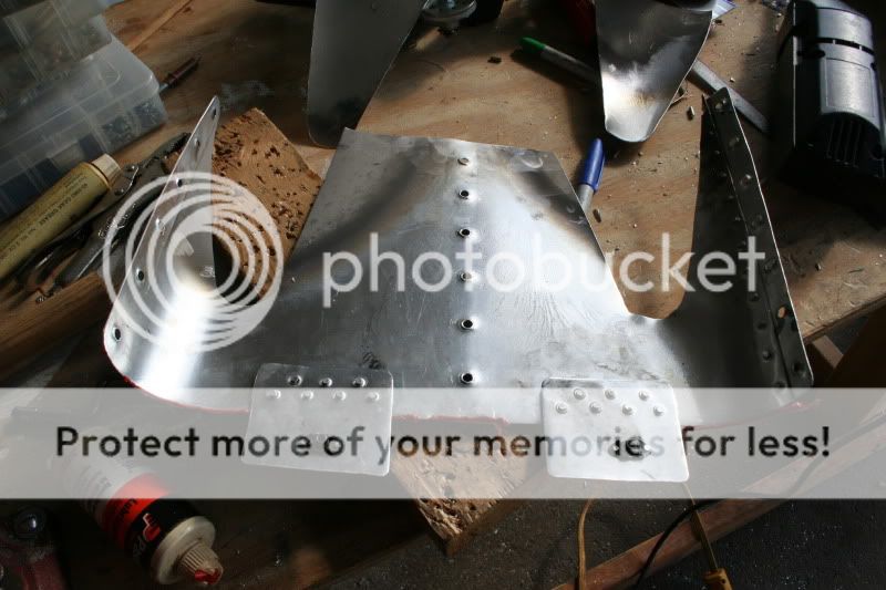
Before I reinstalled the cover I washed it down with alcohol and a paper towel so I could see the new deposits after the next test.
Bob Axsom
I removed the inlet plugs and made the cutouts.
This photo is the inside of the cover after I removed it to cut the exhaust relief openings. Notice the difference in the two sides. The tail end of the exhaust pipes are similarly placed with respect to the stock outlet. It kind of looks like the pairs of cylinders are not performing the same.
I decided to make a modest initial exhaust vent in line with each pipe and the same shape although I toyed with the ideal of opening them to the size and shape of the exhaust pattern on the cover. I did not for two reasons i did not like the look of it and I can always enlarge them later.
Before I reinstalled the cover I washed it down with alcohol and a paper towel so I could see the new deposits after the next test.
Bob Axsom
Last edited:
Regarding the optimum exit velocity, ccreawford, anything less than the free stream velocity means that there's some momentum loss which is paid for with drag. And an exit velocity higher than free stream means thrust.
Of course, I knew that .. just didn't put two and two together.
Incidentally, measuring exit stream velocity with something like this might help optimize the exit duct by itself:
http://www.wingedshadow.com/howfast.html
I wish
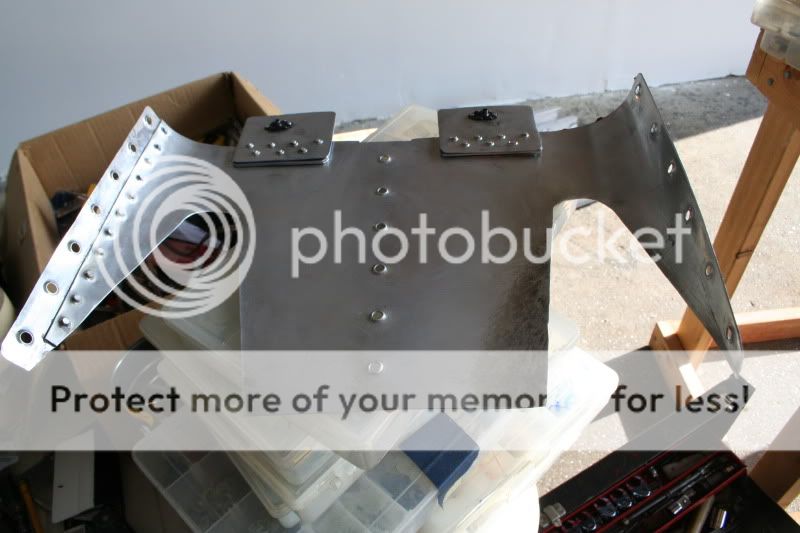
I made the flight with the cutouts and the results were exactly the same at the previous flight 177.2 kts. All my tests are at 6,000 ft density altitude by the way. Manifold pressure 25, RPM was 2730 (that's most I ever get), Oil Temp was 200 which is higher than normal for me. I decided that I wanted to make one more test for today in our unlit airplane with the cover removed. When I removed the cover this is what I saw:
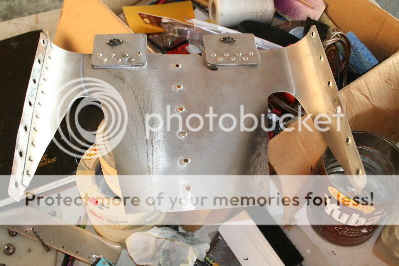
I did a fast turn around and got the test completed without the cover on and landed just before dark (Drake Tower and Razorback Approach worked with me to get it in). The speed was 178.4 but this is not the exact same configuration as I had flown before and got 184.3 kts because now I do not have clean fins and the are two new 3/8" holes in the bottom of the cowl.
My conclusion is that the cover as it is now configured is not as good as the fins without the cover. There may be some unrelated (to the outlet fairing work) performance decay taking place with the engine so it is best to do relative comparisons in limited time windows rather than absolute numbers over a longer period of time.
I am getting very limited sleep so I may not present the information in the best light. I have many more photographs and if you don't see something that you think is important tell me and I will see if I can dig it up.
In the next 18 days I have three races I am entered in, in three different Texas cities so I am going to have to put this experiment on hold and try to get the plane into a competitive condition. I plan to set all of these test articles aside and make up three full length tapered fins out of 2024 T3 0.032" sheet and test fly it one time and focus on race preparation if everything holds together properly. It is going to be a race what you brung situation - no secret break throughs. When things settle down a bit I will get back to this experiment.
Bob Axsom
I made the flight with the cutouts and the results were exactly the same at the previous flight 177.2 kts. All my tests are at 6,000 ft density altitude by the way. Manifold pressure 25, RPM was 2730 (that's most I ever get), Oil Temp was 200 which is higher than normal for me. I decided that I wanted to make one more test for today in our unlit airplane with the cover removed. When I removed the cover this is what I saw:
I did a fast turn around and got the test completed without the cover on and landed just before dark (Drake Tower and Razorback Approach worked with me to get it in). The speed was 178.4 but this is not the exact same configuration as I had flown before and got 184.3 kts because now I do not have clean fins and the are two new 3/8" holes in the bottom of the cowl.
My conclusion is that the cover as it is now configured is not as good as the fins without the cover. There may be some unrelated (to the outlet fairing work) performance decay taking place with the engine so it is best to do relative comparisons in limited time windows rather than absolute numbers over a longer period of time.
I am getting very limited sleep so I may not present the information in the best light. I have many more photographs and if you don't see something that you think is important tell me and I will see if I can dig it up.
In the next 18 days I have three races I am entered in, in three different Texas cities so I am going to have to put this experiment on hold and try to get the plane into a competitive condition. I plan to set all of these test articles aside and make up three full length tapered fins out of 2024 T3 0.032" sheet and test fly it one time and focus on race preparation if everything holds together properly. It is going to be a race what you brung situation - no secret break throughs. When things settle down a bit I will get back to this experiment.
Bob Axsom
Last edited:
hydroguy2
Well Known Member
not the results you wanted but quality work figuring it out. Get back on a good sleep schedule and the testing/brain work will be easier.
For me, I'm kind of in a holding pattern also. I've got plenty to do before I head south for the Hill Country race. Plane is definitely running cooler with the internal outlet baffle, but no real speed gain. Today I tried another comparative run, but to rough at 6600'DA to be comfortable above 185kts, so I aborted.
For me, I'm kind of in a holding pattern also. I've got plenty to do before I head south for the Hill Country race. Plane is definitely running cooler with the internal outlet baffle, but no real speed gain. Today I tried another comparative run, but to rough at 6600'DA to be comfortable above 185kts, so I aborted.
The barrier for me
Bob Axsom
I envy you on that number. Some day, some magnificent day I'll break 185 but it sure is elusive.blah, blah ... above 185kts,
Bob Axsom
F1Boss
Well Known Member
throttle the exit
Hey Bob:
Fab a new cover, just like the original. Fab a pair of airfoil shaped 'bumps' that fasten to the bottom of the ship, with their high points right at the edge of the outlet. As Dan mentioned, work for about 50% exit compared to the start point. This will squeeze the exit air, accelerating it, reducing drag by both restricting mass flow and accelerating the exit velocity.
Best to make these bumps out of SS, but for testing, you might be OK with alum.
We shall call this 'bump' piece a Coanda Bump.
BTW the outlets on the B25 cowls are built this way, so the idea is not new.
More difficult would be to taper the entire exit to a 50% value...
Carry on!
Mark
Thanks for that F1 Boss
I was planning on Coanda bumps but I was coing to put then up by the firewall. You think back at the tail end will work? That would certainly be a less obstructed area to work in. I assume when you recommend stainless steel you are expecting it to get mighty hot in there as opposed to not even warm right now. I'll try the test with aluminum as you mentioned and go to stainless if it works - I guess that means everything.
Bob Axsom
F1Boss
Well Known Member
Hey Bob:
Fab a new cover, just like the original. Fab a pair of airfoil shaped 'bumps' that fasten to the bottom of the ship, with their high points right at the edge of the outlet. As Dan mentioned, work for about 50% exit compared to the start point. This will squeeze the exit air, accelerating it, reducing drag by both restricting mass flow and accelerating the exit velocity.
Best to make these bumps out of SS, but for testing, you might be OK with alum.
We shall call this 'bump' piece a Coanda Bump.
BTW the outlets on the B25 cowls are built this way, so the idea is not new.
More difficult would be to taper the entire exit to a 50% value...
Carry on!
Mark
I have this configuration in aluminum without any issue...
rocketbob
Well Known Member
As Mark said the reason why the Vetterman fairing works is mostly due to coanda effect of the flow around the fairing accelerating the cooling air and exhaust flows. If you approximate the shape of that fairing as Larry and others have done you will see much better results.
For what its worth
I run all of my 3 leg NTPS speed legs at 6000DA adjusted for temperature, just as Bob does. I run them at 2600 RPM just so that I can always control it to a known number. I have made several runs at max RPM (2680 is what my govenor will give me at it's current setting) in an effort to see what the extra 80 RPM would mean in speed. After many attempts, I could never see any speed increase over the 2600 RPM setting with my WW200RV prop, very stock 180 HP IO-360.
Be interesting to see if you get any increase.
Bob, I was really hoping to see you get the magic 185. Instead you have just gotten a bunch of work and disappointment and no sleep. I wish it were different.
I'm thinking of adjusting my prop governor to get a little more rpm....I'm limited to 2610 right now.
I run all of my 3 leg NTPS speed legs at 6000DA adjusted for temperature, just as Bob does. I run them at 2600 RPM just so that I can always control it to a known number. I have made several runs at max RPM (2680 is what my govenor will give me at it's current setting) in an effort to see what the extra 80 RPM would mean in speed. After many attempts, I could never see any speed increase over the 2600 RPM setting with my WW200RV prop, very stock 180 HP IO-360.
Be interesting to see if you get any increase.
Bob, I was really hoping to see you get the magic 185. Instead you have just gotten a bunch of work and disappointment and no sleep. I wish it were different.
F1Boss
Well Known Member
PICTURES!
Give us a peek!
Mark
I have this configuration in aluminum without any issue...
Give us a peek!
Mark
Temporary flow fences made and installed but not tested
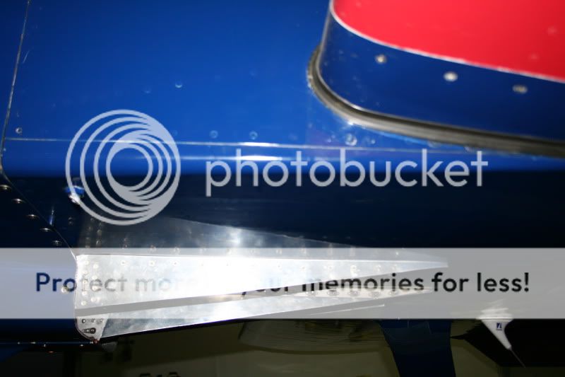
Weather permitting I fly this tomorrow. While working on these a good implementation for the confifigutstion described by F1 Boss came to me. If I had another day I would try to get it in before Taylor on Saturday but the possibility of doing before the Llano race on the following saturday is high.
Bob Axsom
Actually, I think I can make it
I've been thinking about this new Venturi/Coanda idea from F1 Boss tonight and I think I can get it for Taylor If I salvage the old parts with patches instead of remaking them and mount the "bump" on angle brackets defining the shape on the old 0.090" flow fences. Instead of mounting with platenuts I could tap the bracket holes 6/32 or 8/32 or instead of the brackets I could rivet aluminum blocks to the flow fences and drill and tap them. I'm going to give it a shot. I will not have time to test the new triangular flow fences but if this doesn't test out the way I like I will just install the triangles again and race with them untested. The are seen as no risk.
Bob Axsom
I did test the triangular flow fences
The speed jumped up to 181.5 but the right non-sensor LASAR mag failed so I am not gong to work on the latest mod idea for a while. Working through Aircraft Spruce to see if I can get one overnighted from anywhere. SUCCESS! Amy just called back and and said she found a supplier with one in Canada that they are going to overnight to me. $2600+ and shipping cost. The plane is in race configuration with no lights and I'm entered in the race in Taylor, Texas Saturday over 400 miles away. This is going to be TIGHT! In a pinch I can install the tip tanks so I can mount the stock tips and fly at night or fly part way and try to get there before race start on Saturday.
Bob Axsom
The first part is in my plan
In my mind I see a pretty neat set up between the fins. For right now at least I'm going to stich with just making fixed specimens to test. That is a very good idea though. I just finished installing the new LASAR mag going to Taylor at dawn - weather permitting - need sleep.
Bob Axsom
In my mind I see a pretty neat set up between the fins. For right now at least I'm going to stich with just making fixed specimens to test. That is a very good idea though. I just finished installing the new LASAR mag going to Taylor at dawn - weather permitting - need sleep.
Bob Axsom
hydroguy2
Well Known Member
Good luck at Taylor Bob. Hope the winds settle down for you folks....or at least before I get there next week.
BTW, Yesterday, I went to warm up my oil for a change. I had adjusted my prop governor to get a little more RPM. So I made short run down the valley. I ran the prop up 50 more RPM than before(2600 now 2650) and no speed increase. And I actually topped out at 189kts. I'm thinking my 192 I saw a few weeks ago was a fluke. BUT I am running cooler than last year.
BTW, Yesterday, I went to warm up my oil for a change. I had adjusted my prop governor to get a little more RPM. So I made short run down the valley. I ran the prop up 50 more RPM than before(2600 now 2650) and no speed increase. And I actually topped out at 189kts. I'm thinking my 192 I saw a few weeks ago was a fluke. BUT I am running cooler than last year.

