What's new
Van's Air Force

Don't miss anything! Register now for full access to the definitive RV support community.

Edge Distance on HS Front Spar Doubler - RV-7

AndyWW

Well Known Member
A month ago, I hit a snag on the front spar of the HS of my new-build 7, where the edge distance on the holes I drilled in the doubler HS-00001 from HS-710 was very marginal and the spar wasn't straight enough for my liking (see related thread http://www.vansairforce.com/community/showthread.php?t=124011). After a long holiday, my re-ordered parts arrived 3 days ago and I've got to the stage where things went wrong last time (about to match-drill HS-00001 and HS-702). The instructions are a little unclear and look to me like they were probably modified rather than being completely re-written after the doubler was introduced last year to fix the cracking AD. I was about to dive in and try again, but then my wife suggested I post here to ask if anyone has any great suggestions or insights.

The basic issue is that when fixing the position of the doubler it is very hard to see in advance what the edge distance is going to be when the holes outboard of the bend lines are drilled into the "ears", and there is very little room for error. Tiny changes in orientation or positioning can make the edge distance insufficient, and there is inevitably some variation due to the extent to which edges have been smoothed etc. It is tempting to make the bends in HS-710 and HS-714 prior to match-drilling in order to have a better idea of the positioning, but even if I did this it would still be difficult to determine the edge distance before it was too late since the front spar HS-702 is between the 710 and the doubler.

The other, and perhaps related issue, is that the 2 clecos that hold the 710 or 714 to the spar are both close to its center, and they actually allow a fair bit of movement at the end of the spar. So I think that it might be possible to improve upon the suggested procedure of just setting the clecos and match-drilling. I'm certainly going to incorporate a measurement of spar straightness this time!

Any thoughts much appreciated. Part of the problem here is perhaps that this section of the instructions is new so there isn't much accumulated wisdom available yet.
 
Thanks for sharing, Raymond. AndyWW, hope the video is helpful. Try clamping the doublers in place then marking the existing holes on the doubler. Feel free to contact me through my website if you have any other questions.
 
Are you referring to the holes being drilled WITH the ribs?

I just finished prep on all the HS parts and am ready to rivet them all together.

The only thing I can remember being slightly close to edge distance was the 4 holes that you drill after everything is assembled with the ribs. Sec D-D shows 7/16" from the top to the hole and the bottom 1/2". For these holes if you look closely at View A-A the top hole gets pretty close to min edge distance on the HS-710. Vans informed me its okay to get a little over edge distance on the ribs and other parts in this area but the 710 is structural so be sure not to get it too close. I just measured the measurements out that were on the plans and drilled slightly smaller distance than the 7/16" called for. All worked out well.

Hopefully thats helpful.
-Tim
 
Thanks for the answers, especially the video - for those that haven't seen it already, it's well worth watching. It doesn't correspond exactly to my situation since to be totally clear, I'm talking about the initial step in the fresh construction of the HS front spar, using the new instructions which incorporate the doubler from the beginning. This is well before the holes for the ribs are drilled.

The problem I have is that if I go ahead with all new parts, there's only one hole in the spar to look through at the rivet lines on the doublers. The best thing I can think of so far is to use a rather elaborate measuring procedure to try to infer where the holes will come out for a given position of the doubler.

I could try a combination of new and old parts (I reordered HS-702, 710, 714 and 00001) but I haven't managed to think of a combination which wouldn't risk perpetuating at least some of the misalignment I had last time.

Does anyone know of any reason why I shouldn't taper and bend the 710 and 714 before drilling them to HS-702? That would make it easier to estimate where the holes outboard of the bend line are going to end up. Another way might be to use the old 710 and 714 to figure this out.

I'm curious how other people have done this step - there must be a few people by now who have created a new HS since the doubler was added?
 
Hi Andy

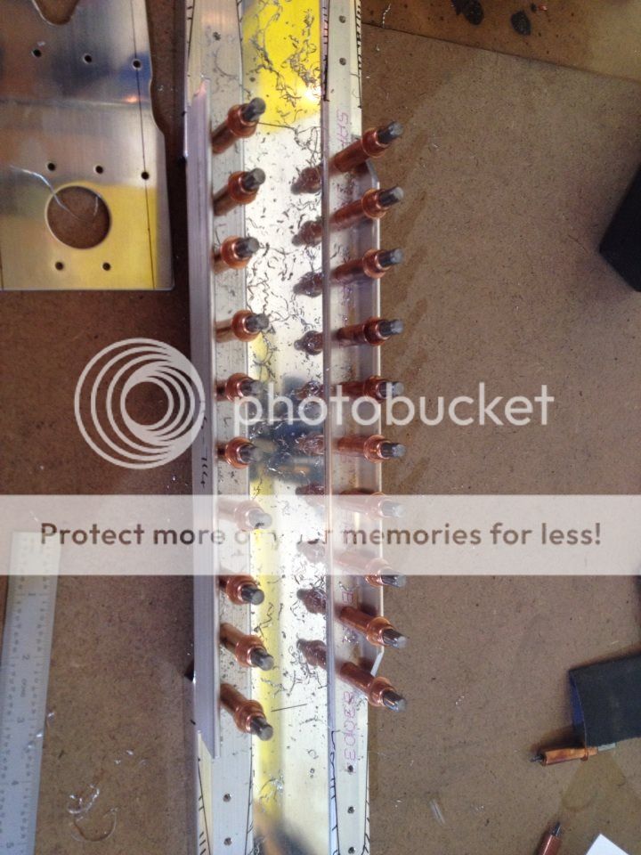
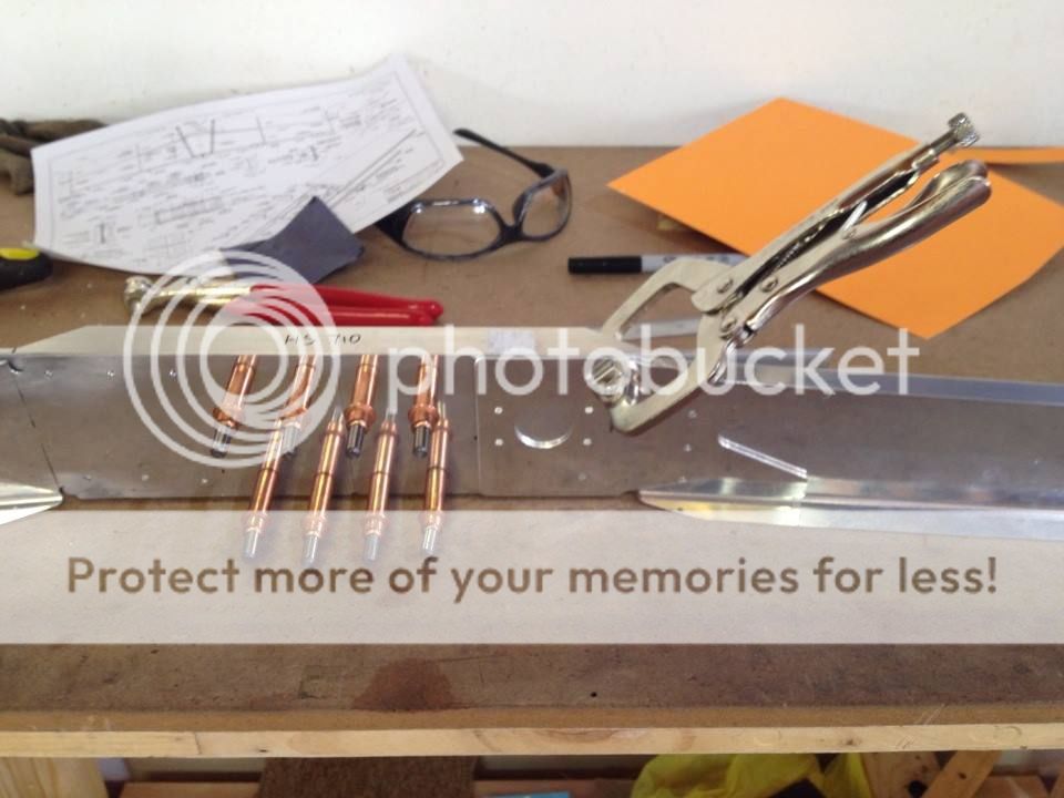
I have been racking my brains to remember this step, and it doesn't help at all that the instructions seem to make no more sense than they did a year ago, they really are appalling! But then I found this photo of the two angles drilled to the HS-702 channels, but without the 00001 doubler in place, and I think that may be the answer! The instructions start by telling you to cleco the 710 and 714 angles to the 702 channels. The very next step tells you to trim the spar channels, apparently with the angles still in place, a seemingly useless step! I think Vans have omitted to mention that while the angles are clecoed to the channels they should be match drilled (only inboard of the ribs mind you). This will then allow you to see the lines they tell you to draw on HS-00001 later on. Its difficult only having these pictures and a fading memory. With the raw parts in front of you does this make sense? or did you do this anyway and still have a problem?

One other thing I'd like to mention is that minimum edge distances are not always absolute and exemptions are common. As Tim mentioned above, I also had less than minimum edge distance on the rib flange but vans Ok'd it. Before the SB most guys got the edge distance issue on the nose rib flange, and it was usually ok. Given that the HS-00001 is a honking thick piece of metal with more than two dozen rivets through it, and was not even considered necessary in the original design, it is a classic candidate for an edge distance exemption, but only Vans can grant that.
 
Last edited:
Hi Ed - Thanks very much for the very useful photos and insightful reply. I found what you said about the instructions quite intriguing - I'd also noticed that there seemed to be an odd cleco/un-cleco foxtrot going on, and I think your theory makes a lot of sense. I tried to follow the instructions even though they seemed strange, and it didn't end well. I am very tempted to try your method. Ultimately I think the most important issue is to get a straight spar and this seems like a good way to get it.

So the proposal is to insert an extra step in the instructions as follows:
1) Ignore the doubler to begin with and drill the holes inboard of the bend line from the 710 and 714 though the spar, making sure it is straight before drilling.
2) Use the newly drilled holes to make sure the doubler is positioned correctly, by sighting the previously drawn rivet lines through the holes.
3) This should solve (or at least mitigate) the edge distance problem on the doubler ears.

As you point out this is a perfect place to use the tolerance allowed on edge distance, and measuring the distance between the edges of the ears on the doublers, compared with the distance between the lines of holes on 710 and 714 suggests that some tolerance is guaranteed to be required. I just want to make sure it isn't asymmetric (on my first attempt the right side was ok but the left wasn't).

Can anyone think of any reason this isn't a big improvement on the current instructions?
 
HS instructions

Andy
I built mine twice. The second time was to correct an egg shaped hole from the SB.
On the second pass with all new insides, I tried to document the process because the manual was difficult.
Check my blog, "empennage" page. Scroll to the bottom.
 
Success!

Thanks to everyone for their tips. I drilled yesterday using Ed's suggestion and it seems to have turned out well. The key was to keep checking the mid-points of the spar ends against the long center line during the drilling process, since these can move around quite a bit when things are only clecoed near the center. The only issue I had was one hole in each spar that got slightly enlarged (0.137") due to being match drilled twice (once with HS-714 and once with the HS-00001 doubler). I can't check the edge distance on the doubler ears until they are drilled later on, but it looks very promising and much better than last time.
 
Match drilling

Andy
Predrilled holes are #41 and #31 or 1/8". If you match drill with the smaller bit there's more room for error. It does add time when you go back and final drill to size.
 
Good stuff!

Great Andy, glad to hear it went well the second time. keep us posted on how it all comes out after you've drilled the ribs. This whole section is something of a baptism of fire, but the good news is that once you have succeeded you will have a lot of confidence moving forward.
 
Frustrating!

Getting the edge distance right on the rivet holes in the HS-00001 spar doubler has been a source of extreme frustration for me. On my first attempt at the HS forward spar I followed the instructions to the letter. Perhaps I should clarify that. I followed the instructions as best I could because the instructions in a number of places make no sense whatsoever. Anyway, I got to the stage where the final holes are drilled through the HS-710/714, HS-702 and HS-00001. When I checked the HS-00001 I found that the edge distance on one of the holes was insufficient. You?ll see what I mean in the picture below ? not even close to the required twice the rivet diameter.

2niu2ih.jpg


So I rang Van?s to see if this might still be acceptable. Well, they weren?t prepared to commit one way or the other simply saying that I was in uncharted waters if I left it like that as no engineering analysis had been done on smaller edge distances here (or something like that). I opted to do the forward spar again and ordered the necessary parts. In the meantime I embarked on a quest to find out where I had gone wrong and what I could do next time to make sure I got it right. I searched the forums and a bunch of builder?s websites to see if anyone else had experienced problems with the spar doubler. I found this thread and Andy?s advice on a better process to follow made a lot of sense to me. I also had a look at the dimensions of the spar doubler and the dimensions of the HS710/714 when in place attached to the HS-702 spar. Now this is interesting. When the HS710/714 are correctly in place attached to the HS-702 spar, the distance between the centres of the outermost holes on each is 2 3/8?. Now the width of the HS-00001 spar doubler at the outer end is 2 7/8?. This means if you take out 2 3/8?for the distance between the holes you are left with ?? which is the exact amount you need to account for the right edge distance for each of these holes. In other words there is zero tolerance for any slight misalignment! If you can?t understand my description here maybe this pic will help.

2s8mw5t.jpg


My new parts arrived and I set to work with all my new found information determined to get it right. I used Andy?s process and I was able to line up the lines on the spar doubler through the holes in the HS710/714. They were perfectly aligned and so I was very confident that things would work out this time. Nope. The edge distance on one of my holes is still too small (better than the first attempt though). Talk about frustration!!!!!!

What to do? I could build this thing a hundred more times and still not get it right because as I mentioned before there is zero tolerance for any slight misalignment. I suspect getting it right would be just sheer good luck. What to do, indeed? And then I stumbled on this little gem ? MIL-R-47196A. It?s on the Van?s web site ? look under support and then the Construction FAQs. This is the standard which allows the shorter shop heads on the rivets in the centre elevator hinge bearing and if you read through it you will find that the minimum edge distance for a 1/8? rivet is 0.219?. And when I check my rivet hole I find this.

2uzceut.jpg


Looks like just a smidge over 0.22? to me ... think I?m saved!

Well after that rather long post I would really welcome other builder?s comments on anything I?ve written above. Are my assumptions, calculations and research correct or am I just a numpty without a clue (need a little encouragement at this stage folks). I?m especially interested in others experiences with the dreaded spar doubler where it?s been part of a new build.
 
Hi Ian, I think you are correct about the zero tolerance, and also that the milspec edge distance. My second try came out less than 2D but greater than 0.219" so I was happy. I think we would both agree that the instructions are less than optimal for this step. The other issue is to get the spar straight because the clecos at the center of the spar do allow a fair amount of movement at the spar ends. I managed to satisfy myself on both issues at the 2nd attempt and have been moving forward. I would advise others to be extremely careful at this step, and measure everything 5 times before drilling! To me it sounds like you are in good shape, so don't be discouraged....
 
Question

Andy, Ian
It sounds like both of you found the same frustration with the HS parts and Vans manual. You both did exactly as you should. Always question it.
I'm glad you got through it. There are many more areas like that ahead and the skills you show will get you through them.
It makes me nuts to find a part exactly the dimension for edge distance but it still needs to have to be debured so there's no way to keep edge distance in tact. Grrrr.

Here's my process.
After venting all the cuss words because Vans engineered a part with an edge distance violation...
Ask Vans before drilling. Usually someone has asked before. Mark minimum on the part and use a center punch to keep the drill bit from wandering. Start with a small pilot hole and enlarge one step smaller than final size. Final size use a reamer.
 
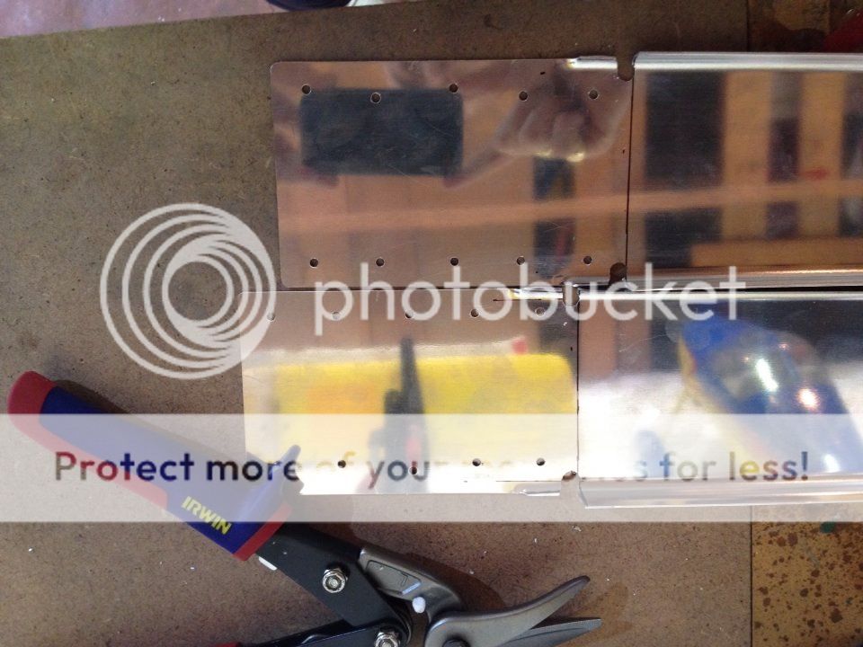
Thanks Andy and Larry. I?m much happier moving on with the build now. I guess these little frustrations just add to one?s education during the build process. I did think of a couple of ways to overcome the problem. One is to fabricate your own doubler with the ears slightly wider than the stock item. This would give that bit of needed tolerance. The other would be to drill all the holes in the HS-710/714 and HS-702 and then place the spar doubler in place so that the exact position could be obtained.
 
I had one single hole on my doubler that had horrible edge distance.

When I talked to vans about it they told me since the doubler was kind of an after thought due to the cracking they thought that edge distance shouldn't be a huge deal on the doubler, as long as the other parts all have edge distance.

The spot mine has edge distance issues is where the doubler attaches to the HS-0005, HS-702, HS-710. They said as long as the reinforcement angle piece had good edge distance I should be fine, which all 3 parts had proper distance, just not the doubler. If anyone here disagrees with that I'd like to hear your thoughts (a little late on this post but I've been in and out of town the last 3 months and am finally getting back into building.)

HS and VS are done and rudder elevator are nearing completion.

-Tim
 
Last edited:
reviving this old thread... it's been an excellent help.

I have one small observation to add

In my set of plans section F-F shows the detail of trimming the spar tabs back and maintaining minimum distance from skin rivet hole. This section of the drawing is noted to be 3/4 scale, but from what I can see, it's actually full scale (based on height of the spar).

As confusing as this section is... even a minor thing like that makes me nervous when I pick up the drill.
 
just started the fight...


can someone tell me if the 4 3/16 holes should be match drilled to #30 now or just wait until the fuse mounting as in the plans and jump right to 3/16

Wont be abel to debur if nothing is drilled now. Plans are un clear.

also watch out for these edges. leave an 1/8 than hammer them flat like the plans say. i got lucky with edge distance here as per Vans.

Where I'm at.
I'm pretty much at the same spot :).

For the moment, I have match drilled to #30 - that is a good question on going to 3/16".

I believe there is a reference to this on page 8-16 FITTING THE HORIZONTAL STABILIZER.

Drawing 27A, View C-C shows how the holes are used.

The section I referenced above says:

Clamp the horizontal stabilizer to the aft fuselage. The stabilizer must be perpendicular to the longitudinal centerline of the fuselage. Pre-position the inboard edges of the skins parallel to the longerons. Check by running a tape measure from the outboard end of the stab to the corner of the firewall. Use similar points on both sides of the airplane and adjust the stabilizer until the measurements are equal.
Install the F-799 wing root fairing as shown on DWG 38, Wing Root Fairing Installation Detail, and Section G-G.
Once the stabilizer is located, it is time to drill the holes though the HS-714 attach angle on the forward spar

Based on that, I'd say we have to wait - but my only qualification is sleeping at holiday inn - so maybe someone more experienced can answer :)

I think I'm with you, #30 makes sense for now rather than leave it undrilled. Than 3/16 drill later during fuse installation.
any others care to chime in before I start drilling...
 
I think I'm with you, #30 makes sense for now rather than leave it undrilled. Than 3/16 drill later during fuse installation.
any others care to chime in before I start drilling...
I guess the shavings will fall into the stabilizer and forever bother me.
 
Back
Top