What's new
Van's Air Force

Don't miss anything! Register now for full access to the definitive RV support community.

Testing Stall Warning Switch

rockitdoc

Well Known Member
Sponsor
I'm installing my stall warning switch in the wing. Want to make sure it works. Here's what I have discovered, so far:
Step 1 - Continuity from center push tab to ground is good

Step 2 - Upper push tab to center tab (ground) are connected (closed) when switch is not activated (down, level flight or at least not stalling, but in fact, these two are connected even when switch is up, ie, stalling. Is this correct?

Step 3 - How do I figure out if the switch works. Been through the wire diagram a couple of times, but can't seem to figure it out. Hence, this post....
 
That doesn't sound quite right. The centre tab is Normally Open and should not be wired to ground. The tab on the long side of the switch is Common and gets wired to ground. The third tab is Normally Closed and does not get connected. The switch should be "off" at rest and "on" when the vane is up because the wing is stalling.
 
Right, You Are!

That doesn't sound quite right. The centre tab is Normally Open and should not be wired to ground. The tab on the long side of the switch is Common and gets wired to ground. The third tab is Normally Closed and does not get connected. The switch should be "off" at rest and "on" when the vane is up because the wing is stalling.

I took the switch out of the wing....Again.

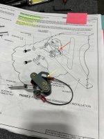
Tested it for continuity. Plans are incorrect. The red arrow shows where the plans have the ground connected. This is incorrect for this switch. The ground should be connected to the tab on the top of the switch, yellow arrow (in fact, the switch is marked indicating this is common, or ground). The center tab is the one that gets connected to +12v (and, this is marked indicating 'on'). I tested this by continuity and found that the center and top tabs are connected when the switch is up, or stalling. The bottom tab is not used, for some reason. Anyway, now I know how to test it when in the wing to make sure I have enough travel to activate the switch.

Stall Warning Switch.jpg
 
I took the switch out of the wing....Again.

Tested it for continuity. Plans are incorrect. The red arrow shows where the plans have the ground connected. This is incorrect for this switch. The ground should be connected to the tab on the top of the switch, yellow arrow (in fact, the switch is marked indicating this is common, or ground). The center tab is the one that gets connected to +12v (and, this is marked indicating 'on'). I tested this by continuity and found that the center and top tabs are connected when the switch is up, or stalling. The bottom tab is not used, for some reason. Anyway, now I know how to test it when in the wing to make sure I have enough travel to activate the switch.

View attachment 23374

If you are only using the normally open and common pins on the switch then it doesn't matter which one of those is connected to ground. Also if one side is connected to ground don't connect the other side to +12v. If you do when the switch is closed you have a direct short to ground. I think you are building a 14 but the 10 plans clearly show the Normally Open pin connected to ground and the common pin connected to the audio board, those could be connected either way it doesn't matter. You just don't want to use the normally closed pin.
 
Like ColoradoDolar wrote, it doesn't matter which wire connects to which terminal as long as the correct two terminals are used. The stall vane switch is not polarity sensitive. The label "COM" does not mean ground. That terminal is common to the other two terminals. Connect the wires to "N.O." and to "COM".
 
I was wrong....again.

I took the switch out of the wing....Again.

Tested it for continuity. Plans are incorrect. The red arrow shows where the plans have the ground connected. This is incorrect for this switch. The ground should be connected to the tab on the top of the switch, yellow arrow (in fact, the switch is marked indicating this is common, or ground). The center tab is the one that gets connected to +12v (and, this is marked indicating 'on'). I tested this by continuity and found that the center and top tabs are connected when the switch is up, or stalling. The bottom tab is not used, for some reason. Anyway, now I know how to test it when in the wing to make sure I have enough travel to activate the switch.

View attachment 23374

All comments were correct. And, I stand....corrected. The plans are correct, again...

The center tab on the switch is 'no', or normally open. The top tab, the long one, is common. The bottom tab is 'nc', normally closed. So, if the center, or n.o. tab is grounded, when the stall arm moves upward in a stall it closes the switch and grounds the common tab causing the warning to go off. As stated by others, it doesn't matter which tab, the n.o. or common is grounded.
 
Back
Top