F-315 Seat Bulkhead Sequence
I figured I'd better add a few notes to the discussion
on my VAF blog about riveting the F-315 seat rib to the F-303 spar bulkhead since not everyone will see that.
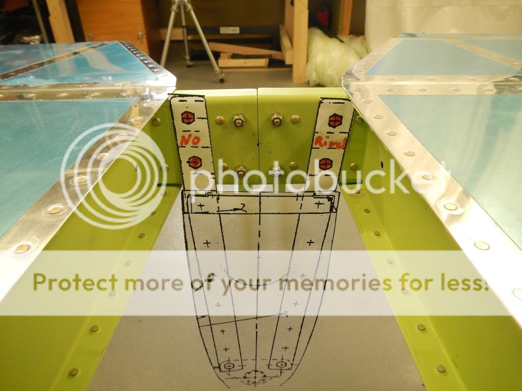
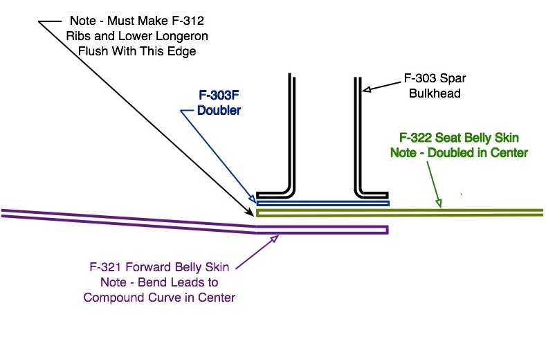
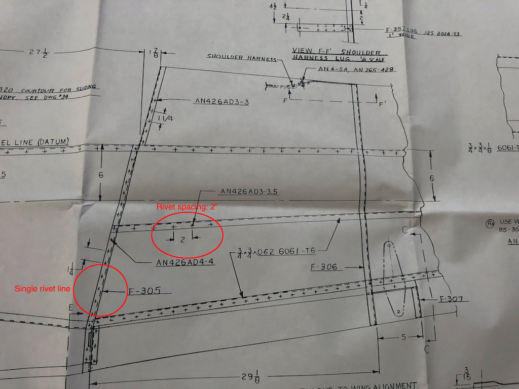
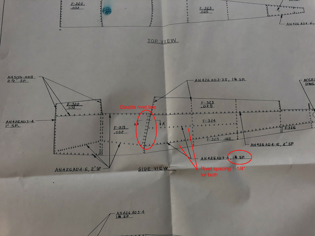
I think that the best way to do this is to rivet the rivets shown in the red oval while the aft bulkhead is still separate from the forward one. At this point it's a simple matter of back-riveting the joint, and the seat rib can be bent away for clearance. The bulkhead won't be drilled for the F-303F splice strip or the F-303E side plates yet.
After this, the bulkheads can be joined with the F-303F splice strip, but the F-303E side plates ought to await having the bulkhead on the jig with the longerons. Then the side plates can be drilled through the F-315 seat ribs webs at the blue oval. Once that's done, the seat ribs can be formed so that the ribs have a joggle around the side plates by using a flange fluting tool.
I failed to do that and went ahead and riveted the F-303F splice strip on too early. This was handy for jigging up the bulkheads and the longerons. When I wanted to rivet the F-315 seat ribs to the bulkhead, I discovered that it was going to be difficult. You can read about that in post #306.
I followed this sequence for the overall seat rib installation:
1. Uncleco and remove the F-315 seat ribs.
2. Uncleco and remove the F-303E side plates.
3. Countersink the end plates.
4. Uncleco and remove the F-313 center seat rib.
5. Uncleco and remove the F-304 bulkhead.
6. Uncleco and remove the F-314 seat ribs.
7. Rivet the F-304 bulkhead to the F-313 center seat rib.
8. Cleco the F-304 bulkhead to the F-305 seat bulkhead.
9. Rivet the F-304 bulkhead to the F-305 seat bulkhead.
10. Cleco the F-314 seat ribs in place.
11. Rivet the mixer brackets to the F-314 seat ribs. In my case, some of those rivets also went through the F-304 bulkhead or the flanges already riveted to the F-303 aft bulkhead, and I left these unriveted for this step.
12. Rivet the F-304 bulkhead to the F-314 seat ribs, including the mixer brackets.
13. Rivet the F-314 seat ribs to the F-303 aft spar bulkhead, including the mixer brackets. For some reason this was harder than I expected, due to the various other parts in the area interfering with it.
14. Rivet the F-314 seat ribs to the F-305 seat bulkhead.
15. Rivet the F-315 outer seat ribs to the F-303 aft bulkhead.
16. Rivet the F-303E side plates to the F-303 spar bulkhead and the F-315 seat ribs.