What's new
Van's Air Force

Don't miss anything! Register now for full access to the definitive RV support community.

Revision to SB-00036 document and replacement parts

Status
Not open for further replies.

greghughespdx

Well Known Member
Advertiser
NOTE: Reporting has been set up on its own thread so we can more effectively communicate the SB revision info here. If you've come here to report your airplane's results, please visit this thread instead and post there - thanks!

Our engineering team is reviewing the manufactured parts shipped as part of SB-00036 and has issued a revision to those parts due to an unanticipated potential fatigue issue that was just discovered. As a result, we have placed all pending shipments on hold until that process has been completed. We have also published SB-00036 REV1, which includes the inspection steps but has the steps related tp installation of the new hinge brackets removed (we will update with new instructions once the new parts are ready). It also includes information outlined in this post.

We've sent an email notification to customers who were already shipped SB-00036 kits. Those kits contain replacement outboard elevator hinge brackets for RV-4/6/7/8 aircraft. We are also emailing all builders who received the newer hinge brackets in their RV-7 and RV-8 tail kits in late 2022 and January 2023.

Builders/owners who have received these parts but have not yet installed them are advised to hold off on installation and wait for replacement parts. If you have installed them on a flying airplane, you may continue to operate the aircraft until the revised parts are available, at which time they will need to be replaced.

If you ordered the SB kit but have not yet received a shipment notification from Van's, know that we have placed your order on hold until the new parts are available. A kit with the new parts will ship to you automatically as soon as they have been manufactured and received. For those who have not already, you can also pre-order the SB kits on the Van's web store, and they will be shipped as soon as the new parts are available.

Van's is prioritizing the production of these new parts and we will strive to ship the replacement parts as soon as possible.

We recognize and apologize for the trouble this unexpected revision creates for builders and owners who have already received - and in some cases installed - the problem parts, and the delays shipping to those with parts on order. We take the revision process very seriously. Due to the potential fatigue issue with the affected parts it was deemed necessary to replace them.

We will communicate with affected customers via email and - of course - here on VAF about this in the next several business days, once we have a timeframe established for the revised parts.​
 
Last edited:
I'd like to add: Our team works hard to provide solid parts and service information. In this case, an issue was not caught and made its way into the field. The moment our engineering team realized there was a problem, they jumped into gear to address the problem right away.

We will produce the revised parts, the design of which has received a highly-focused review by several members of our engineering team, as quickly as possible so we can get the parts to builders/owners.

For those who have already installed these parts, we are truly sorry for the situation. We know it's not a good one. Ultimately, whatever it takes to help ensure your safety and the quality of the products we produce is the very most important thing we do.

Thank you.​
 
Any idea on time frame?

I will post that information here as soon as it is available. This change has literally just happened and we are working through the manufacturing details right now, so we have a couple of steps to complete here before I can communicate the timeframe. Know that we are expediting and production of these parts has high priority.

I'll post info just as soon as we have the details.
 
This caught my eye

... don't recall seeing it discussed in the original thread when the forces acting on the brackets, rivets and spar were being speculated about. From the SB text:

"...the interaction of airframe vibrations and the elevator, which can result from failure to dynamically balance the propeller."

I'm glad none of these cracks have been reported on any 10's yet, but as a guy flying a -10 that seems "smooth enough for me, for now" without a dynamic balance done, it got my attention.

Edited to add: I'm curious what percentage of the fleet has undergone a current propeller dynamic balance.
 
... don't recall seeing it discussed in the original thread when the forces acting on the brackets, rivets and spar were being speculated about. From the SB text:

"...the interaction of airframe vibrations and the elevator, which can result from failure to dynamically balance the propeller."

I'm glad none of these cracks have been reported on any 10's yet, but as a guy flying a -10 that seems "smooth enough for me, for now" without a dynamic balance done, it got my attention.

We have observed a pattern on multiple aircraft in terms of locations of the cracks that are addressed by the service bulletin, which leads us to suspect vibration- and pulse-related forces from the propeller can play a part. That said, we are not saying by any stretch of the means that prop vibration is the sole cause of the cracks when they occur.

Edited to add: I'm curious what percentage of the fleet has undergone a current propeller dynamic balance.

Me too. Maybe we should start a poll. I can say with confidence that a dynamic prop balance is a simple and effective way to reduce vibration and fatigue-related damage to the airframe. I can also say that when an aircraft's prop balance is "off," the pilot often only knows and experiences the individual airplane he/she flies, and in that respect, it's all relative. I know many RV owners who truly believed their prop was balanced and smooth - until they completed a dymanic balance!
 
Dynamic Prop balance hard to detect (in my experience)

Long time lurker here :)
But I thought I'd chime in that I was not able to detect a difference after getting the 3 blade composite Hartzell Explorer dynamically balanced.
(this is on an RV-14 running the 390 EXP119)

I'd flown it about 75 hours at the time it was balanced, and have flown it ~50 since.
As described above, Hartzell explained that it was unlikely I'd notice, even if there had been significant harmonic resonances which may have been removed by dynamic balancing.
Basically, it is a good idea to get it done even if the effects are not noticeable to your butt in the seat.

Steve
 
Greg,

I'm wondering if, for those that are fabricating new horizontal stabilizers, if there might be a better, or equivalent, reinforcement to prevent the issue. A fairly large doubler on the forward face of the HS-603PP rear spar may be equally effective as the modified hinge brackets.

This idea certainly would not help with completed, in-service stabilizers. For those, the new hinge brackets seem the best solution (once the current issue is resolved).

But for new construction, it might be simpler, lighter, easier means of reinfocement. It is equivalent to the reinforcement to the elevator spar in the region of attachment of the hinge rod bearing, which has similar loads (although perhaps not similar dynamic loads due to prop vibration).
 
I'm sure guys are still working out the details, but when you can let us know, for those that have already received the initial sb36 parts, will you be providing the rev1 replacement parts for free?
 
Greg,

I'm wondering if, for those that are fabricating new horizontal stabilizers, if there might be a better, or equivalent, reinforcement to prevent the issue. A fairly large doubler on the forward face of the HS-603PP rear spar may be equally effective as the modified hinge brackets.

This idea certainly would not help with completed, in-service stabilizers. For those, the new hinge brackets seem the best solution (once the current issue is resolved).

But for new construction, it might be simpler, lighter, easier means of reinfocement. It is equivalent to the reinforcement to the elevator spar in the region of attachment of the hinge rod bearing, which has similar loads (although perhaps not similar dynamic loads due to prop vibration).

The forward doubler seems like a huge improvement with essentially zero downside. Possible even worth opening the skin.
 
I'm sure guys are still working out the details, but when you can let us know, for those that have already received the initial sb36 parts, will you be providing the rev1 replacement parts for free?

Yes, the replacement parts for those who received them in a recent kit or as part of the SB-00036 kit will be provided and shipped free of charge, as soon as available.
 
That's great support, I have the first SB kit, now I'll wait for the new one. I scoped the inside of the HS, no cracks. I had a condition inspection due in July and I'll be waiting until then to do the SB. Thanks Greg.
 
The forward doubler seems like a huge improvement with essentially zero downside. Possible even worth opening the skin.

Low Pass, although a doubler on the forward side of the spar may strengthen the area, perhaps one of the downsides (albeit a small one) is that it can hide an underlying crack developing in the spar underneath the doubler, making any future internal inspection more difficult. Although I am formerly an engineer, I only feel qualified to ask questions. My question would be does the engineering team think the solution proposed is right in all situations solutions, or should new construction also include a doubler? If so, in my situation, I'd err on adding the doubler for insurance since I'm going to open up my partly unfinished HS, but for most other flying RV's it might not be justifiable.

Shout out to Greg Hughes on speedy communication in this thread. Thank you all.
 
I just did the inspection on my 80s era RV-4 (1900 hours, some aero) and found no cracks. Apparently the builder of my plane preemptively installed a doubler on the forward side of the spar; on both sides I found a single doubler that spanned both brackets, along with a fifth center rivet on all four brackets. The shop heads of the rivets are on the forward side of the spar on my plane.
 
I just did the inspection on my 80s era RV-4 (1900 hours, some aero) and found no cracks. Apparently the builder of my plane preemptively installed a doubler on the forward side of the spar; on both sides I found a single doubler that spanned both brackets, along with a fifth center rivet on all four brackets. The shop heads of the rivets are on the forward side of the spar on my plane.

The only problem with a fwd doubler, as pointed out in another post,,
You really can’t inspect the spar for cracks, per the SB.

When/if a crack does become visible, could be too late if it shows itself at the flange, then you will need to replace the spar.

Not sure what I would do in your case.
 
I just did the inspection on my 80s era RV-4 (1900 hours, some aero) and found no cracks. Apparently the builder of my plane preemptively installed a doubler on the forward side of the spar; on both sides I found a single doubler that spanned both brackets, along with a fifth center rivet on all four brackets. The shop heads of the rivets are on the forward side of the spar on my plane.

Does the double only pick up the same 4 corner holes as the hinge fitting? Center rivet does not do much since the loads are mostly carried in the corner rivets.
For the doubler to be effective it needs to extend beyond the fitting and have another row of rivets inbd and outbd past the fitting attaching the doubler to the spar. If not, you are still dumping the same load into the spar web through the same 4 corner rivets. The doubler maybe making it stiffer (maybe not a good thing) but it is not really making the spar web stronger to react the fitting loads.

Yes, I agree it is best to extend a doubler beyond the footprint of the bracket and have additional rivets around the perimeter.

Also agree that you can't inspect under a doubler - but that is always the case with all doublers, which are common. In particular, the elevator spar has similar doublers in the area that the plate nuts for the rod hinges attach when the repair in SB 14-02-05 is complied with.

Remember, my suggestion/question was for new construction. The idea is that with additional reinforcement, that area would not crack. Noting that the cracks seem to be fairly rare to begin with (opinion based on slowly growing statistical sample as people report their findings).
 
This below text reposted from a Facebook thread. Unfortunately there have been a few people making statements about alternative methods of addressing the issue that others are taking as gospel (so to speak, please forgive the phraseology). In the interest of safety, I wanted to also include it here to make sure the information is shared equally. This post is certainly not pointed at any one person. :D

TL;DR: An approved fix is coming. Please wait for Van's to release more info.


Anything contradicting the below statement should be considered incorrect until the Van's official fix is released. Refer to service documents on the Van's Aircraft web site Support>Service Information page.

SB-00036 addresses a problem that has begun to appear in the fleet, in which horizontal stabilizer rear spars of RVs have slowly developed cracks at the location where the outboard elevator hinge brackets are attached. The SB-00036 document specifies an inspection of the front and back of the horizintal stabilizer for cracks, and if cracks are found, remediation of the issue.

If cracks are found, and if they are limited in size as described in the bulletin, the owner will need to stop-drill the cracks. After that, a set of parts that will be made available from Van's Aircraft will need to be installed. We recently released a set of parts for the RV-7 and RV-8 to accomplish that fix process, but due to another issue that was discovered with those replacement parts, we stopped shipping them. We are now finalizing a revision of those parts, which will be available to ship soon. We will also be releasing parts for other RV models in the near future.

We STRONGLY recommend that people DO NOT ENGINEER THEIR OWN SOLUTIONS and that they instead pause and wait for our engineering team to complete the revision of the new parts, about which we will communicate further information soon.

We have observed a handful of people on Facebook and other Internet forums stating that "the fix" is a doubler plate of non-specified thickness or design. These people are, quick frankly, incorrect. Their proposed solution is not approved by Van's engineering staff and should not be considered safe. There are a variety of forces at play that contribute to the fatigue issue being addressed, and any improper design may very well introduce new, additional problems that are not obvious. Attachment of the elevator is a critical aspect of the aircraft design, so we cannot stress enough the importance of waiting for our team's review to be completed and the new parts produced before making any changes.

We will have further answers soon, most likely by the end of the day on Monday.​
 
Last edited:
Yes, I agree it is best to extend a doubler beyond the footprint of the bracket and have additional rivets around the perimeter.

Also agree that you can't inspect under a doubler - but that is always the case with all doublers, which are common. In particular, the elevator spar has similar doublers in the area that the plate nuts for the rod hinges attach when the repair in SB 14-02-05 is complied with.

Remember, my suggestion/question was for new construction. The idea is that with additional reinforcement, that area would not crack. Noting that the cracks seem to be fairly rare to begin with (opinion based on slowly growing statistical sample as people report their findings).

Our team is testing revised designs. The inclusion of extended doublers such as Steve mentions has been reviewed, and designing parts/attachment methods to further reduce concentration of loads is all part of the ongoing design process.

I should also note that there are a number of aircraft on which this issue has been observed since the release of the service bulletin, and many of those examples are not posted here on VAF. In at least one case, the cracks were quite severe and clearly require the replacement of the horiz stab rear spar.

You'll hear back from us on Monday by the close of business with an update. I'll continue to communicate significant info updates as they happen.
 
Last edited:
Our team is testing revised designs. The inclusion of extended doublers such as Steve mentions has been reviewed, and designing parts/attachment methods to further reduce concentration of loads is all part of the ongoing design process.

Thanks Greg for the response. Thanks for letting us know that the question/suggestion is in the mix of ideas being explored.

I apologize if anyone interpreted my question/suggestion as a recommendation.
 
Thanks Greg for the response. Thanks for letting us know that the question/suggestion is in the mix of ideas being explored.

I apologize if anyone interpreted my question/suggestion as a recommendation.

No, wasn't yours. Was elsewhere. Just being overly cautious. Appreciate you! :)
 
Our team is testing revised designs. The inclusion of extended doublers such as Steve mentions has been reviewed, and designing parts/attachment methods to further reduce concentration of loads is all part of the ongoing design process............

Again, thank you Greg for all your efforts on what appears to me now as outstanding/proactive communication. Vans is demonstrating to me its commitment to transparency and integrity to its community, and although its benefit may be unmeasurable, I have no doubt this sort of leadership serves both the Vans community and the Business extremely well over the long haul.

Loyal customer and RV8 builder

Future beer on me at the mothership. May you finish your RV 8A long before me.
 
Thanks Greg for keeping the crowd well informed.
Thanks to the Vans engineers for coming up with sensible solutions.

My borescope is on its way and will be put to work ASAP.
I'm not overly worried about cracks as I only flew 80 hours since new.
And there are none visually from the outside as I check on every pre-flight.

I'm more preoccupied by the statement that "the interaction of airframe vibrations and the elevator, which can result from failure to dynamically balance the propeller."

And I won't dispute that unwanted vibrations can produce failures.
Just wondering how many of us dynamically balanced their props?
Presumably, less than more.

My local, friendly prop shop suggested to dynamically balance it after 50 hours or so of operation when I picked it up after assembly.
Given that a correctly dynamically balanced prop has a number of advantages, I will setup a rendez-vous soon.
 
Another Data Point

2001 RV-8, 2,300 hours, mild aerobatics, factory head on Fwd side of spar, no cracks.

LT%20HS%203-XL.jpg
 
IS Elevator flutter part of the vibration source

Greg ... Has the cracked spars been linked to Vne excursions leading to minor flutter issues with elevators? Will be inspecting our RV7A next month... 900hs with a 2008 build date. We did have the prop / engine dynamically balanced at 100hrs, but we have had the prop off since. We marked the prop, ring gear and crank studs to be sure it all went back together in the same location but I'm thinking it must be done each time the prop comes off?
 
We have observed a pattern on multiple aircraft in terms of locations of the cracks that are addressed by the service bulletin, which leads us to suspect vibration- and pulse-related forces from the propeller can play a part. That said, we are not saying by any stretch of the means that prop vibration is the sole cause of the cracks when they occur.

There are many variables that can lead to the cracks in a H-tail TE spar at the elevator hinge bracket. I would be interested to see the data on why you may think it is “vibration- and pulse-related forces from the propeller”. Getting more statistical relevant data will really help so hope those with cracks report on more than just if the have had their prop dynamically balanced.
 
I have seen several posts here and on facebook about this SB.

What I am trying to clarify is would it be a problem to drill a new hole mid way between the front spar and rear spar to insert a borescope to see inside, rather than trying to enlarge the existing hole that is towards the back just ahead of the rear spar.

The scope I am wanting to use is not that fancy and has no sideview camera and I do not believe I will be able to insert it in that rear hole and get a bend on the scope capable of seeing the rear spar area.

Called Vans this morning and the gentleman I spoke to did not advise that it was ok to do so... but then someone else on FB said they had a email from " Sterling " at Vans saying it was ok to do a new hole " on the centerline of the rib, maintain 2D or better edge distance and keep the hole to a minimum will not pose any risk ". The person that sent me that, did a hole midway between the spars and did his inspection then covered the hole with a sticker to cover the hole till next year.

I would like to do a similar hole and want feedback. Thanks Ron
 
Data points:

2004 -8A, 875 hours, has flown acro but I don’t know how much - only hit 3.5G a handful of times in the last 3-1/2 years: No cracks. (Will probably be up for sale pretty soon here, we need a bigger cabin.)

2010 -7A, 200-some hours, I don’t know if it’s flown acro: No cracks.

Almost-new 9A, less than 100 hours: No cracks.
 
I received the new hinge brackets today. THESE ARE THE BRACKETS THAT VANS HAS REJECTED. One of my concerns with the non pre punched stabilizer is the rivet spacing on the rear spar adjacent to the hinge brackets is not uniform from build to build. This is the case on my stabilizer, the rivets that are supposed to go through the new bracket and the skin and rear spar will not have adequate edge distance on the hinge bracket. I hope this issue is addressed with the new brackets that are in the works.
 

Attachments

  • 0C561B58-6663-402D-99BE-A37123B7C6A2.jpg
    0C561B58-6663-402D-99BE-A37123B7C6A2.jpg
    168.3 KB · Views: 365
I note that with just a flashlight I can see the forward rear spar part of the outboard brackets just fine through the lightening holes in the end ribs of my RV-9A. Getting an endoscope in there for a definitive inspection should be straightforward, in the RV-9/9A at least, if one thinks that is necessary. No drilling required. Zooming in the photograph makes me pretty confident that an endoscope isn't required either (for the -9/9A).


..
 

Attachments

  • F2B38604-8A70-432C-A828-1DC83D970058.jpeg
    F2B38604-8A70-432C-A828-1DC83D970058.jpeg
    240.3 KB · Views: 123
  • 5263684B-AC9B-4DCD-8514-AB505923BFA7.jpeg
    5263684B-AC9B-4DCD-8514-AB505923BFA7.jpeg
    442.5 KB · Views: 150
Last edited:
Progress update on replacement parts

Our team's made substantial progress on the final design and testing of the replacement SB parts for the elevator hinge brackets. We have scheduled manufacturing time, and we will be able to update further in the next couple of days, at which time I expect to be able to share a more specific timeline.

A few people have inquired whether they should expect parts in the next couple/few weeks, vs. multiple weeks or months. We are striving to get parts out the door as soon as possible. Assuming no major roadblocks between now and then (and roadblocks do sometimes happen), our target timeline is within the next couple of weeks. (Please don't quote me or tell anyone I told you that, though. It's just between us.)

Note that we will probably provide the parts - at least initially - without powder coat applied, which will allow us to get them out the door and in your hands as soon as possible. The owner/builder will just need to clean the steel parts and apply a coat of self-etching primer before installation.

We will post additional info soon. Thank you again to everyone for your understanding and patience.
 
Fits through existing tooling hole

The camera listed below fit through the existing tooling hole and worked fine for me. It can be found on Amazon for slightly less cost than through Depstech's website. I did see some other vendor had a 3.5mm camera rather than the 3.9mm on this one, but was unable to find if for sale.

I liked the WiFi feature so I didn't have to worry about any USB OTG problems with whatever version of Android I happen to have on my phone / tablet. It works with Android and IOS - I didn't try a PC.

https://depstech.com/collections/wifi-endoscopes/products/wifi-endoscope-wf070

900ish hours, RV-7A, no cracks.

Regards,
Rob
N706DR
 
Rear spar on 7A vs 14A

A friend is building a -7A. He says his HS rear spar is 0.032" 2024-T3, and comes without lightening holes. On the -14(A), it is 0.063" 2024-T3, with six 2" lightening holes between the elevator hinge brackets and two more outboard of the outboard hinge brackets. There are a few more smaller lightening holes inboard of the inboard hinge brackets. Anyone have data points for other models, e.g. the -6(A) and -8(A)?
 
Last edited:
A friend is building a -7A. He says his HS rear spar is 0.032" 2024-T3, and comes without lightening holes. On the -14(A), it is 0.063" 2024-T3, with six 2" lightening holes between the elevator hinge brackets and two more outboard of the outboard hinge brackets. There are a few more smaller lightening holes inboard of the inboard hinge brackets. Anyone have data points for other models, e.g. the -6(A) and -8(A)?

Well, the -8 and the -7 are the same, so, 0.032". And given that the part number is HS-603PP, I', betting the -6 is the same too.
 
Note that we will probably provide the parts - at least initially - without powder coat applied, which will allow us to get them out the door and in your hands as soon as possible. The owner/builder will just need to clean the steel parts and apply a coat of self-etching primer before installation.

Greg, what is the Van's recommendation for a self-etching primer that provides a level of corrosion protection equivalent to a powder coat finish?
 
More cracks

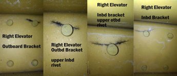
I had to replace my horizontal stab and elevator back in 2015. I found a completed stab and elevator and installed them on my 8. At that time my airframe had 2250 hours on it. It now has 3300 hours, so a bit over a thousand hours on the new stab and most definitely some acro..

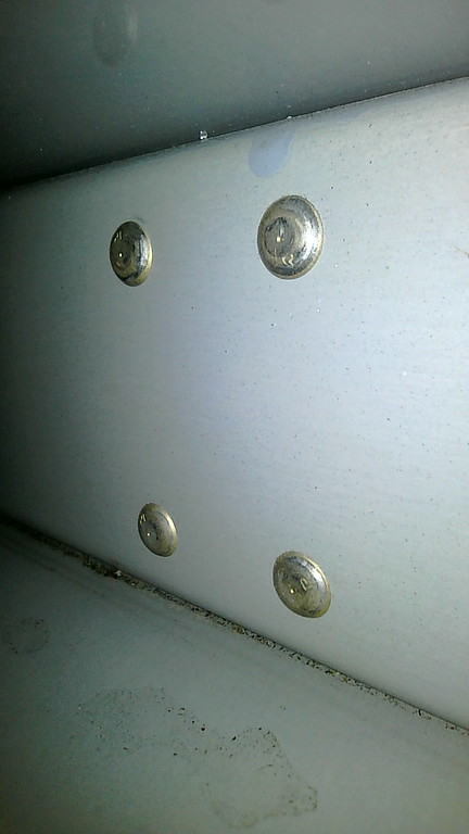
As you can see from the photo's I do have 2 cracks on the right hand, outboard elevator attach brackets. The left brackets have none. The rivet where the crack is on the outboard attach point was obviously not set properly. The inbd attach point also has a crack in the upper adjacent to the crack in the outboard one. This leads me to believe that the reason for the crack may be poor assembly in the first place. Just speculation, but it was not build properly.

Also, I plan on replacing both sides when the parts are available since I can see other rivets that just aren't right here.

SB 00036 4 photos jpg.jpg
 
Cracks on inboard hinges?

When I first reviewed the service bulletin the pessimist in me couldn’t help but question why it required an inspection of the outboard hinges, but not the inboard. After reading the post and viewing the pictures by RV8iator I now decided it was time to ask why the SB doesn’t require inspection of the inboard hinges? My 9A is simple enough to inspect the outboard hinges, but it will require a boroscope to inspect the inboard.
 
Left side cracks?

I have not yet seen reports of cracks in the left side. Have I missed these?
Also, I am familiar with an RV-8 case that almost assuredly (pending consultation with the mothership engineers) that will require rear spar replacement. Anyone know the parts list that this will require? I suspect not solely the spar, but I can’t find details.

My RV-8 appears crack free at approx 330 hours TT, aerobatics to 3.8g max, no snap maneuvers, WW200RV prop dynamically balanced. Shop heads facing aft.
 
When I first reviewed the service bulletin the pessimist in me couldn’t help but question why it required an inspection of the outboard hinges, but not the inboard. After reading the post and viewing the pictures by RV8iator I now decided it was time to ask why the SB doesn’t require inspection of the inboard hinges? My 9A is simple enough to inspect the outboard hinges, but it will require a boroscope to inspect the inboard.

The inboard hinge brackets are located on a much thicker substrate than the outer hinges. (Inner hinge on spar web .032", reinforcement bars .187")
 
My guess is the spiral slipstream caused by descending prop puts a greater load on right horizontal stab. Jerry, my crack is identical to your right side, outboard bracket, upper inboard rivet. What should a proper rivet look like? I have 950 hrs on 2004 rv8 with little aerobatics. I guess it’s not so obvious to a non builder.
 

Attachments

  • CA56806A-4466-4050-B5AF-ED6851B16B2A.jpg
    CA56806A-4466-4050-B5AF-ED6851B16B2A.jpg
    58.5 KB · Views: 434
Last edited:
Good and Bad

Jerry, my crack is identical to your right side, outboard bracket, upper inboard rivet. What should a proper rivet look like?.

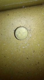
Properly set. there are gauges to check proper height and diameter.

Properly sest.JPG


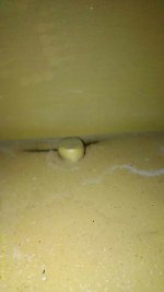
Not Proper. Not how the shop head is bent, not round and not even around the hole. I didn't build either, but this is pretty obvious...

Not set properly.JPG
 
Hmm....

My guess is the spiral slipstream caused by descending prop puts a greater load on right horizontal stab.

However, the same slipstream putting a load on the left stab as well - Only from the bottom.

Let's also not forget about that same slipstream putting a side load on the vertical stab/rudder...any crack sightings on the VS-803PP/VS-413PP?
 
When I first reviewed the service bulletin the pessimist in me couldn’t help but question why it required an inspection of the outboard hinges, but not the inboard. After reading the post and viewing the pictures by RV8iator I now decided it was time to ask why the SB doesn’t require inspection of the inboard hinges? My 9A is simple enough to inspect the outboard hinges, but it will require a boroscope to inspect the inboard.

The inboard hinge brackets are located on a much thicker substrate than the outer hinges. (Inner hinge on spar web .032", reinforcement bars .187")

Also, I would expect the most stress to be on the outboard hinge due to the weight of the counterbalance, and this is exacerbated by vibrations from the engine/prop as they are propagated through the airframe. Think of the ends of the horizontal stab being sorta like the end of a diving board or tuning fork or the tip of a bullwhip...it can vibrate quite violently especially at a harmonic frequency and the stresses on that outboard hinge may be quite high at times.
 
A friend is building a -7A. He says his HS rear spar is 0.032" 2024-T3, and comes without lightening holes. On the -14(A), it is 0.063" 2024-T3, with six 2" lightening holes between the elevator hinge brackets and two more outboard of the outboard hinge brackets. There are a few more smaller lightening holes inboard of the inboard hinge brackets. Anyone have data points for other models, e.g. the -6(A) and -8(A)?

In addition to the thicker spar material, the RV-9/10/14 series have the advantage of the rear spar being constant height from root to tip. I haven't measured the differences but with the tapered stab profile on the 3/4/6/7/8 models, the vertical height of the rear HS spar web at the location of the outboard hinge is quite a bit smaller than on the 9/10/14. I would expect the stresses on the hinge attachment rivets to be lower on the 9/10/14 models, all other things being equal, although I don't know the weight difference of the outboard elevator & counterbalance.

Has anyone discovered cracks on the 9/10/14 models?
 
Bad riveting

My guess is the spiral slipstream caused by descending prop puts a greater load on right horizontal stab. Jerry, my crack is identical to your right side, outboard bracket, upper inboard rivet. What should a proper rivet look like? I have 950 hrs on 2004 rv8 with little aerobatics. I guess it’s not so obvious to a non builder.

Tracy, looking at the top inside rivet in your photo, it’s not squeezed properly either. And on the opposite bracket, the top and bottom rivets closest in don’t look right either. Just speculating here, but the way it looks, it can’t be distributing the load as it should.
 
Tracy, looking at the top inside rivet in your photo, it’s not squeezed properly either. And on the opposite bracket, the top and bottom rivets closest in don’t look right either. Just speculating here, but the way it looks, it can’t be distributing the load as it should.

I was concerned about some of the shop heads on the bracket rivets on my RV-6, they looked over-driven. Then I figured out the very wide field of view of the borescope was distorting the view of the rivets making them look "flatter" than they actually are when viewed nearly straight on. Moving the scope to a different angle revealed that they were in fact properly set. I suspect that is what is happening in the image referenced above in Tracy's aircraft.
 
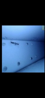
My RV-9A was checked this week. I was able to insert my Vividia-400 Ablescope into the outboard lightening hole on the aft HS spar, then use the articulation to point over to the hinge rivets.

No cracks!

S20230206_0006-M.jpg

This is just one photo of several I was able to take. I wasn't able to get all of the rivets in a single photo.

This airplane has 1052 hours over almost 9 years. No aerobatic use.
 
Status
Not open for further replies.
Back
Top