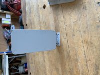
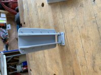
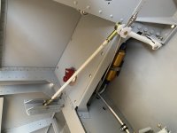
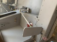
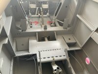
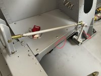
I've partnered my -8 "Special Delivery" with Bruce Bohannon, CFI of Pushy Galore & Exxon Flyin' Tiger fame for the purpose of designing a robust rudder & brake system for the back seat.
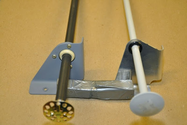
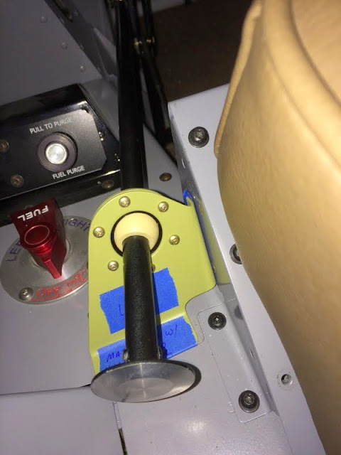
An official announcement will be coming soon, but you've heard it first here on VAF; the FAA has approved the rudder/brake system and just two days ago issued Bruce a LODA to conduct RV-8 transition training. He's currently engineering the system to work with ground adjustable pedals so I don't expect he'll be offering plans or kits any time soon. Sorry. I've flown the front seat to test his 'back seat' ability to override my rudder/brake inputs, and except for a pilot that might lock-in both legs which will get him/her a severe jolt to the back of their head, the geometry and linkage works as designed and is simply amazing. Seems that all it took was to tell Bruce it couldn't be done!
So... stay tuned for the 'official' announcement; "RV-8 transition training available in an RV-8" ...and coming soon thereafter, "RV-4 and RV-3".


 Oh, and you guys are really thinking outside the box if you're going to do transition training in a -3