What's new
Van's Air Force

Don't miss anything! Register now for full access to the definitive RV support community.

RV 14 Plan "Gottchas"

I am not sure that this is a "gotcha" or not. But I think that the seat ribs in the finishing kit have changed. Section 55 shows that the 3/4" holes for the stick wire bundle have a rounded notch out so that the rectangular connector and be pushed through (check out Van's revision of plans and the notch is clearly there). I am not sure when that changed. It is clearly not in any of the plan revisions that I have looked at so far. Section 25, 28, and 29 all show the ribs with round 3/4" holes. Maybe I missed where it is called out in the plans to make this notch out. Also, the 3/4" holes in the tunnel sides F-01451 are not notched.

Also, install all the snap bushings before running the wire harness. I put in the WH on one side with out doing this and boy is it a pain to do after it is in place.
 
...Section 25, 28, and 29 all show the ribs with round 3/4" holes. Maybe I missed where it is called out in the plans to make this notch out. Also, the 3/4" holes in the tunnel sides F-01451 are not notched.

I haven't checked since I built to see if they added the notch to the plans. In my case, I received a piece of paper (not a plan revision page) with the fuselage kit that had a drawing with instructions to add the notch.

I don't recall the time frame of when I ordered the fuselage kit, but it had been out awhile before I finished up the empennage kit and the wing kit. The single sheet drawing I received may not have been in the earliest deliveries of the fuselage kit.

That said, this is the only part of the Van's wiring kit that I ended up replacing. I found the connector that goes through this hole to be too vulnerable to working. It is a mini molex that really needs to be held rigidly or the pins can work loose and come out of the connector. I replaced these connections with D subs after that happened on one of the sticks (long before first flight).

In the end, you can just remove the connector and feed the stick wiring through the unmodified hole. Don't try removing the pins and reinserting them in the mini molex. Per Molex specs, these are one shot pins, they are not meant to be removed and reinserted.
 
Not sure this is a "gotcha", maybe it should be added to the "common mistakes" spreadsheet even though it is not a mistake. It is more "it makes life easier".

So I am installing the WH-00125 and other electrical stuff in the fuselage and I found it relatively annoying to install the ground wires for the sticks and the 12 V power supply.

Van's should supply jumper wires for the stick which are a ring terminal to a spade terminal, then have a spade terminal on the WH-00125. Then one could install the ground jumper when before the parts are put in or when they are installed but easy to access. Since the ground wires for the sticks are relatively long, just clip off the ring terminal and replace with a spade terminal and make the jumper wire yourself.

The 12 V power supply would be even easier. All that one needs is a 4" wire with a ring terminal and a female spade terminal and attach to the rib during installation. Again, why van's doesn't supply this wire in the fuselage kit is beyond me?

Maybe ground wires aren't supposed to be spliced, so this would be a stupid idea.
 
Fuel Senders

Not really a "gotcha", rather this is a heads up that even though the fuel senders look identical, they aren't. There should be a 385B stamped on one ground plane, and 385C stamped on the other of the two senders. You will know immediately if you have put the wrong sender in the tank because the screw holes won't line up and it will hold the sweeper mechanism at an angle.
 
Riveting rudder left hand attach strip / bottom rib

07-10 Step 2 has you rivet the aft 8 rivets common to 3 items - skin, bottom rib and attach strip. It never asks you to rivet the one hole aft of the attach strip - common to only the bottom rib and skin.

7-10 Step 3 then has you rivet the bottom ribs together with blind rivets.

This makes it almost impossible to reach the last rivet on that line next to the trailing edge wedge. Some builders have had to drill out the blind rivets or buck the rivet against the opposing one.

Not certain if this is a plans error, but I think in Step 2 it should say to rivet the aft 8 common to the skin / rib / attach strip AND rivet the one common to the skin and rib. All this is done before you rivet the two bottom ribs together.

$0.02 YMMV

Boy, I?m glad you posted this.... I did that single rivet while I was also doing the eight on the attach strip.
 
Fluid fitting Section 31

On page 31-05 figure 1 it shows the fitting clocked at 25* off horizontal. Then on page 31-11 figure 2 & 3 show a different clocking based on gear configuration. According to Van's use 31-11.
 
In the trash

Just a heads up that the Google sheets file is, "in the owner's trash" and won't be available much longer. I made a copy of it just in case.
 
I thought that there used to be a copy of the actual plans with edited "gotcha" notes somewhere in the forums, but I can't seem to locate them any longer. Anyone know if they were moved, or if they still exist?
 
12-02 Rudder bottom Fairing

Page 12-02 Step 2 states "Drill #30 two holes on each side of the R-911 Rudder Bottom Fairing as shown in Figure 2. Take care to keep the holes
within the area defined by the scribe line. Remove the area up to the scribe line on the rudder bottom fairing as shown in Figure 2".

Pay attention to figure 2 as it shows a straight cut along the top of the fiberglass within the scribe line. DO NOT FOLLOW THE SCRIBE LINE AROUND THE FRONT OF THE RUDDER FAIRING. If you do so then you will end up with a funky looking fairing and realize you just screwed up.

12-02-1.jpg
 
DO NOT FOLLOW THE SCRIBE LINE AROUND THE FRONT OF THE RUDDER FAIRING. If you do so then you will end up with a funky looking fairing and realize you just screwed up.

I think once you finish the rudder , you will find that you would not be able to install it on the vertical stabilizer if it didn't have that funky shape.....
 
12-02

I went back out and fit the fiberglass to the rudder and the cutout in front actually fits pretty nice. I had to clean up the edges a bit since the scribe line was not equal on each side and the front area had a distinct slant, but once trimmed significantly and fitted to my rudder it looks a bit better.

Lets change this plan gotcha to:

"be weary of the scribe lines symmetry and ensure you cut short before trimming to the specific fit of your rudder. Figure 2 does not match the scribe line on the R-911 Rudder fairing."
12-2-2.jpg


I'll add some Flox to fill the gap in front of the rudder horn once the temperatures here warm up a bit.
 
Last edited:
Page 12-07 step 6 is to attach the rider bottom fairing, but the diagram below specifying the screws has the title ?FIGURE 5: MATCH-DRILLING RUDDER BOTTOM FAIRING?. Obviously this is already done.
 
Coax cable for the transponder that is supplied with the empennage kit is very short and limits your options for installing the transponder. I installed the GTR-45R behind the G3X on the copilot side and the coax cable is way too short. The only place you can put the transponder is behind the center stack between the sub panel and the firewall. I pulled out the original coax and re-ran a longer piece of coax--there goes $50 down the drain. I guess I can sell the coax cable.

I would eliminate the wire from the kit and run coax without the ends. this way you don't have to split all the plastic bushings en route to the tail cone. One has to run GPS, 2 coms, and maybe a NAV cable, so you are going to have to install ends on cables anyway.

just my thoughts.
 
I want to subscribe to the RV-14 forum but I cant find this (from the FAQ): You can also choose to receive email notifications of new posts in a thread without posting in that thread, by clicking the 'Subscribe to this thread' link displayed in the thread page.

Can anyone tell me where "Subscribe to this thread" is displayed?
 
Page 12-07 step 6 is to attach the rider bottom fairing, but the diagram below specifying the screws has the title ?FIGURE 5: MATCH-DRILLING RUDDER BOTTOM FAIRING?. Obviously this is already done.
I noticed that. I think it was a copy-and-paste error. Page 12-07 figure 5 is a duplicate of page 12-02 figure 3, which has that caption, except that the call-outs were changed from drilling and nutplate instructions to the screws to use. They just forgot to change the caption when they copied it over.

That brings me to my section 12 gotcha: Page 12-05 figure 2 calls for CS4-4 rivets in 18 places on the rudder top fairing. There are indeed 9 holes shown in the drawing, figure 2. I was sad to see I only had 8 holes until I looked back to section 7, which shows just 8 holes on each side. (One of which gets dimpled on page 07-04 step 4 since things are too tight to reach that one after you rivet the rudder halves together.)
 
I was referring to the Main Wire Harness 14/14A Kit, Van's part number ES WH-00125 KIT, which is an option. It is not included in any kit. If you are going to order it, order it with the fuselage kit so that you can install it as you build the fuselage.

It is not too hard to install after the fuselage is assembled but it will be a lot easier to install while building. I was very disappointed that it did not come standard with the fuselage kit as the wiring did for the wings and empennage.

On the download page, there is a drawing of the harness and it is detailed enough that you could make your own that would interface with the wing and empennage harnesses.

I completed the fuselage kit and put the plane on landing gear before I ordered the WH-00125. Tonight, as I am partly done installing half of the wiring harness, I feel like that was a mistake.

I wish that I had installed the wiring harness before the elevator control rods (section 36). The Molex connector that goes to the aft fuselage (attaching at the F-01406 aft baggage bulkhead) is going to be difficult or impossible to get through the F-01405 bulkhead with the CS-00001 elevator pushrod in place.

Looking back through the plans, the wiring harness would probably be easiest to install before the side skins (section 29) or maybe even earlier. Definitely, order the wiring harness around the time you receive the fuselage kit.
 
Coax cable for the transponder that is supplied with the empennage kit is very short and limits your options for installing the transponder. I installed the GTR-45R behind the G3X on the copilot side and the coax cable is way too short. The only place you can put the transponder is behind the center stack between the sub panel and the firewall. I pulled out the original coax and re-ran a longer piece of coax--there goes $50 down the drain. I guess I can sell the coax cable.

Yes, the stock transponder coax length is too short, but it can be easily extended. Just cut a length of RG-400 cable to suit, then put a male connector on one end and a female on the other. This solution is fine per Stein, so there's no reason to pull the original coax.
 
Section 29 Gotcha

My latest practice is to identify all the parts for a particular plans' section, then do all the prep work (deburring, drilling, cutting, priming, etc.) for all the parts before assembly. I find this to be far more satisfying when I can blast through a section and really see parts coming together. This approach, however, bit me on the rear in section 29.
Part number F-01405K as depicted in figure 2 on page 29-19 has a mistake relative to steps 5 and 6. The machine countersink note in the upper left of figure 2 says to machine countersink the #40 holes in F-01405K. However this note is wrong and should be pointing at F-01405H instead. F-01405K should be dimpled, not countersunk per steps 5 and 6 on this page.
Now I get to order a new part because I was in "prep mode" and wasn't paying attention to the written step instructions and therefore didn't catch the mistake until it was too late.
 
Rudder tip fairing attachment

I was looking ahead and studying the attachment of the rudder tip fairing. Noticed on page 12-05 that 18 CS4-4 rivets are called for. My rudder has only 16 rivet holes so I contacted Van's about the discrepancy. Seems that, when preparing the rudder skins prior to assembly, an additional rivet hole is supposed to be drilled on each rudder skin offset on either side since there won't be room for the two rivets back to back. Since the two skins are identical parts prior to bending the forward end of the balance tab, the holes can't be punched along with the rest. As I was told, this is done in the RV-7 and RV-9 rudder (the latter shown in the attached drawing).

There's probably not much consequence to the missing holes. In my case, I intend to use Hysol in conjunction with the rivets to attach the fairing. It would probably also be possible to drill the holes after rudder assembly but I could not find any way to dimple them.

For what it's worth.
 

Attachments

  • image001.png
    image001.png
    24.8 KB · Views: 286
My rudder has only 16 rivet holes

Hi Ray,

That’s interesting - mine had 9 holes a side, the aft most one was drilled to #30 and dimpled at page 07-04 step 2 ready for countersinking they fairing at a later date.

EDIT: I can’t count. Mine had 8 holes as well. See other post above.
 
Last edited:
Ahh, it may be that the plans have been revised and I missed that.

EDIT: Just checked. That's not it. Those two holes (one each side) were the last of 8 each side on mine, I'm pretty sure. I remember doing that step. What I was told was that a new hole needed to be drilled in each side, each staggered from the other to allow room for the rivets to go besides each other on the inside.
 
Last edited:
That's not it. Those two holes (one each side) were the last of 8 each side on mine, I'm pretty sure. I remember doing that step. What I was told was that a new hole needed to be drilled in each side, each staggered from the other to allow room for the rivets to go besides each other on the inside.

Well that’s interesting! I just checked as well and I only have 8 holes on each side, not 9 as you mentioned! I don’t recall there being any step mentioned about drilling another hole and in my case it would involve drilling out all the rivets to get another one in there. I wonder if I missed something? On page 7-04 it gets you to drill and dimple the 8th hole from the front because you can’t really dimple it later. Not sure how I would dimple one in-situ further aft where the skins are even closer together.

Here is a photo is my installed rudder fairing - only 8 rivets on each side.
https://tasrv14.blogspot.com/2020/04/12-empennage-fairings-complete.html?m=1#postLightBox-14

Thanks for your pickup - I’m keen to know what the outcome is now and if I have to remove my tip fairing.
 
Last edited:
I certainly wouldn't think this is a show stopper. But it's curious that the instruction didn't make it into the manual.
 
I was looking ahead and studying the attachment of the rudder tip fairing. Noticed on page 12-05 that 18 CS4-4 rivets are called for. My rudder has only 16 rivet holes so I contacted Van's about the discrepancy. Seems that, when preparing the rudder skins prior to assembly, an additional rivet hole is supposed to be drilled on each rudder skin offset on either side since there won't be room for the two rivets back to back. Since the two skins are identical parts prior to bending the forward end of the balance tab, the holes can't be punched along with the rest. As I was told, this is done in the RV-7 and RV-9 rudder (the latter shown in the attached drawing).

There's probably not much consequence to the missing holes. In my case, I intend to use Hysol in conjunction with the rivets to attach the fairing. It would probably also be possible to drill the holes after rudder assembly but I could not find any way to dimple them.

For what it's worth.

I think the rivet count call out is a typo.
The prototypes and the current parts have 8 holes per side.
 
I think the rivet count call out is a typo.
The prototypes and the current parts have 8 holes per side.

It's also the number of holes pictured in the fairing install. And, since this is, to a very large extent, an RV-9 rudder, I would think it would be done the same as the RV-9 (as in the image I was provided by one of your cohorts): starting with 8 holes per side and drilling one additional each side.

Certainly not critical, just a curiosity.
 
It looks like Google will begin automatically deleting anything in a Google Drive Trash folder. If I remember correctly, this Gottcha's file is actually in the original authors trash folder - can the original author speak up, or should we move it to a non-trash location?

Thanks!
 
Rudder cable installation

I don’t know if this has been flagged yet or not, but a number of folks on the Facebook RV-14 site have found they installed the rudder cables backwards, because the plans only say to place the plastic sleeve forward. Turns out, the plans should specify to place the clevis end of the cable aft, instead. The plastic sleeve will slide the length of the cable and in recent kits, the sleeve is apparently arriving on the aft end. I checked and the drawing in section 10 is not clear enough to differentiate the end fittings. A simple note would avoid any confusion and a lot of rework. :rolleyes:
 
I don’t know if this has been flagged yet or not, but a number of folks on the Facebook RV-14 site have found they installed the rudder cables backwards, because the plans only say to place the plastic sleeve forward. Turns out, the plans should specify to place the clevis end of the cable aft, instead. The plastic sleeve will slide the length of the cable and in recent kits, the sleeve is apparently arriving on the aft end. I checked and the drawing in section 10 is not clear enough to differentiate the end fittings. A simple note would avoid any confusion and a lot of rework. :rolleyes:

I made the same mistake, but my kit was shipped back in 2014 so it has been quite a while where this has been happening. It needs to be clarified and I am surprised it hasn’t been by now.
 
I don’t know if this has been flagged yet or not, but a number of folks on the Facebook RV-14 site have found they installed the rudder cables backwards, because the plans only say to place the plastic sleeve forward. Turns out, the plans should specify to place the clevis end of the cable aft, instead. The plastic sleeve will slide the length of the cable and in recent kits, the sleeve is apparently arriving on the aft end. I checked and the drawing in section 10 is not clear enough to differentiate the end fittings. A simple note would avoid any confusion and a lot of rework. :rolleyes:

Thanks Mark for bringing this to my attention today. Jeff and I are both victims.
 
Please save this file!

It looks like Google will begin automatically deleting anything in a Google Drive Trash folder. If I remember correctly, this Gottcha's file is actually in the original authors trash folder - can the original author speak up, or should we move it to a non-trash location?

Thanks!

Yes! I tried to access the file tonight, and it's showing only a single sheet.
Anyone have a recent version available?

thx
 
Yes! I tried to access the file tonight, and it's showing only a single sheet.
Anyone have a recent version available?

thx

This is the one I have been using. Not sure how recent.
 

Attachments

  • Copy of RV14 Master list of common errors - Sheet1.pdf
    87 KB · Views: 1,388
Yes! I tried to access the file tonight, and it's showing only a single sheet.
Anyone have a recent version available?

thx

The "gotchas" spreadsheet is intended to be a single file and single sheet document.

The inventory spreadsheet is a single file with multiple sheets.
 
Section 22: Ailerons

I could not find these plans errors on either the wiki nor the "gotcha's" excel file.

Please excuse me if i have misunderstood the plans or if they have already been identified.

I am working of the aileron plans rev 4/15/2013.

22-02
After step 3 there is an identical step 7. The intent is clear to buff out the facets in the flanges - just a typo.

22-03:
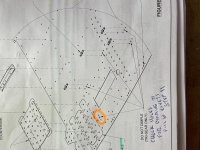
Step 1 asks you to dimple the 0.98 holes in the main ribs (these are the #40 ones). Nowhere on the page does it ask you to dimple 120 degrees the #30 holes in the rib webs (there are 6 holes which connect the upper A-1005A ribs to the lower A-1005-B ribs later on with pull rivets). These are identified to be dimpled in Figure 2 callouts. I dimpled these 100 degrees at this point because i didn't have a 120 degree dimple die. :eek:

22-05:
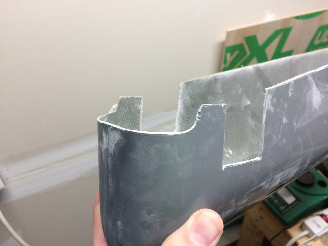
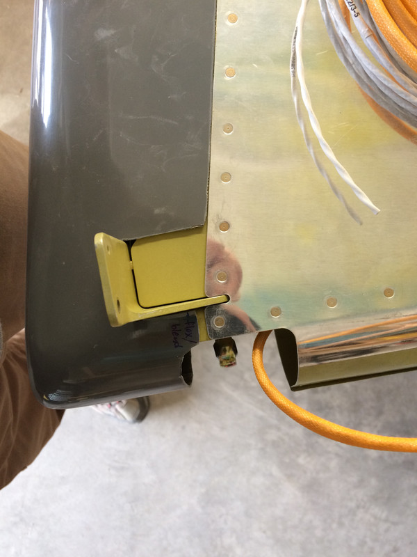
(at this point you have the nose skin clecod to the nose ribs and the 2 end holes of the counterbalance only. You have removed the spar, and you are about to drill the 2 mini tabs at the front of each of the nose ribs to the counterbalance).
Step 1: you drill the lower tab only - i used a 6" long #40 through the lower #30 hole in the aft rib flange (where it would connect to the spar). You then cleco the counterbalance to this rib through the hole you just drilled. You then remove the nose skin.

If you do this, you end up with 2 nose ribs held to the counterbalance with only 1 cleco and it's impossible to keep the ribs aligned.

What i did, is i clecod the nose rib to the counterbalance through the #40 hole i just drilled, then i re-installed the spar to the ribs only (not the skin). Then i removed the nose skin. This kept the ribs in a much better alignment for the next step 2.

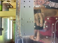
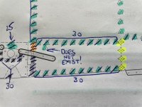
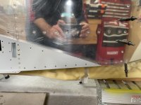
22-05 Figure 1 - This supports step 2; you are supposed to have the nose skin removed, but the image shows the skin still in place.

2 scenarios here: With the skin in place i could not see a way to get a drill bit in to mark the top tab hole to the counterbalance? Perhaps there is a way and in Step 1 you are not supposed to remove the nose skin (which would solve the alignment problem for the nose ribs). Not sure of the intent here. Or, you are supposed to remove the skin to get access to mark this hole, but then you have wobbly unaligned ribs. ???

Step 2: Mark the hole of the top flange etc - this works fine with the nose skin removed and the spar clecod in position as i indicated.
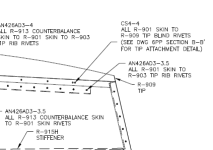
22-07:
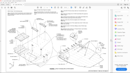
Figure 1 title is "final-drill spar and nose ribs" but there is no instruction step to do this. I assume it is not needed. Also, you are supposed to place the aileron, right side up, on the table with the nose to spar clecos hanging off the edge of the board. Then somehow cleco on the trailing edge? I am not sure how i can do this unless i have a skinny table, thinner than the chord of the aileron? (if anything can shed some light on what they are getting at, that would be great).

Another query if anyone knows, which way did people install the screws and nuts for the counterbalance? Screw heads in the tube, or on the rib flange?

Apologies if i haven't understood the plans properly or if these have already been flagged. Compared to the other plans sections, it feels like these ones are not as polished as the others - I know we are supposed to be expert builders by this stage of the build of course :confused::D
 
Last edited:
Firewall to pump Fuel tube too short

When I made the fuel tube between the firewall and the pump it came out too short (7-8mm / 1/4"-5/16"). I made a new line in the spreadsheet. (Page 31-10, step 4). Advice is to measure before cutting. There was enough tubing to make a new one.
 
Starboard Heater Vent

Found a 'gotcha' today.

The plans in the Exhaust Section have you modify the heater vent on the starboard side to close off the bottom of the vent that was mounted to the firewall way back when the FWF construction began before the engine was mounted.

The problem with this is that the two rivets that are supposed to be drilled out cannot be reached now that everything is in the way. Also, even if these two rivets are drilled out somehow, getting new ones in will be impossible or nearly so.

My solution was to glue the cover onto the outside of the vent with fuel tank sealant and after that cures, RTV. It's not structural, and even if the glued on cover comes loose, it can't hurt anything down there and the only negative result is more heat going to the starboard side until glued back again.

Vent Heater Pass.jpg
 
26-11 - Taildragger - adding rivets into nutplate holes

If you are building a taildragger, on Page 26-11, Step 11 it says: "Fill the nutplate holes in the centre bottom skin with rivets".

It has a picture of a bunch of locations where nutplates should be installed IF you are building a nose-dragger.

However, there is one location which is shown to NOT have a nutplate. In the nosewheel version this gets a nutplate in chapter 29.

Well, don't fill this location with rivets in Chapter 26 by accident - otherwise, in Chapter 29, you get to the point after much work (bolting things together, adding sealant to the exhaust tunnel etc), when you stand the fuselage on it's side to rivet the bottom skin - you will find 3 dimpled holes which already have rivets underneath them!

Ask me how i know! Doh x 10.
 

Attachments

  • Screenshot (57).png
    Screenshot (57).png
    307.9 KB · Views: 83
  • IMG_4022.jpg
    IMG_4022.jpg
    339.7 KB · Views: 81
  • IMG_4020.jpg
    IMG_4020.jpg
    483.6 KB · Views: 74
Last edited:
On page 29-12 you are riveting the side skins.

There is a rivet callout at the back of the skins behind the flaps (in the bay where the step would mount) just above where the curved flap gap angles will mount. My kit didn’t have a hole in that location.
 

Attachments

  • 83D3CB98-F112-4CC6-9E0A-C64881969B8A.jpg
    83D3CB98-F112-4CC6-9E0A-C64881969B8A.jpg
    312.9 KB · Views: 69
  • 70DFADFD-537E-436C-89F3-5B8904EF0229.jpg
    70DFADFD-537E-436C-89F3-5B8904EF0229.jpg
    402.2 KB · Views: 69
Last edited:
Back
Top