What's new
Van's Air Force

Don't miss anything! Register now for full access to the definitive RV support community.

Skyview Avionics Received!

Bill_H

Well Known Member
My Skyview avionics have arrived from Van's! Only a couple of wiring harnesses are on back order (per a phone call from my wife). And here I am stuck in New York on a business trip! But I will be back home tomorrow and get to work!

I ordered my engine last February 2011 if you are wondering, and am totally finished with the plane except for the avionics - including paint. See pics here if you would like.

http://www.facebook.com/media/set/?set=a.151245628228677.26907.100000297210697&type=3&l=a2b29e894a

Bill H.
N412BR
 
That is fantastic news Bill, so happy for you. It also means I am one kit closer to getting mine
 
Bill - Excellent! We're excited to start seeing SkyViews in 12s. Send photos as you install it.

-Robert
Dynon Marketing
 
Can"t wait

Received my skyview kit ordered power plant kit last December 2010.I am away for two weeks so can't work on it till I get home on the first of March.
I wish I had the paper work so I could get a head start but I waited a very long time so I will make the best of it 120210 N145Y some day.
Bayne
 
My kit is also ready. Maybe I pick it up from Van's on the next business trip. Can anyone please provide me the size and weight of the box? (Barb didn't have this data last week).

Thank you, Joeri.
 
I have finally started on the Skyview installation. Here are just a few notes and surprises. My plane is complete except for avionics, wings in their stands.

I started with the wing connection updates. This is straightforward. You are running two additional 18 gauge wires form the wing root to the tip - one to power the strobe separately (the original installation powers the nav and strobe from one wire) and one used to synch the two strobes. If you are building your wing, add these two wires now!

The PANEL
You get a new left panel piece and new center piece. Not a new right piece.
The left piece has the big skyview cutout. It does NOT have the small cutouts above it for the intercom and ELT switch as shown on the demonstrator. You will have to cut those yourself unless you want to put them on the right side of the panel in your existing right-side panel piece that has those cutouts.

Well, I DO want them on the left. The plans say to do that you then order a new right-side piece and new map box parts
F-00035 SkyView Inst Panel Right Mapbox
F-00021 Map Box Door
Printed copy of Section 29A
And a 6 inch piece of hinge (I had spare hinge)

BTW the new center panel piece requires that you add nutplates to holes in the bottom of the center panel piece frame. I had already done that, which was an option in the original plans.

I was missing 8 tiny screws in my kit - check your bags carefully.
Instead of them, the bag contained 8 cotter pins that were not needed.

In what may be an oversight, there are no FUSES in the kit I was sent. They are called out on page 42C-04 of the plans. Neither the main fuses for the switch unit are included, nor the spares shown on that page. It may be that the parts list is more for a retro-fit of flying RV-12s which would already have fuses. I could not find on any of the parts lists where the fuses are called out to have been shipped. I brought this to Van's attention.

If you already have your engine, upgrading to the new fuel pressure sensor is OPTIONAL. If you want it you have to order the sensor from Dynon and a bracket from Vans. The plans include a page on how to wire it in.

This is a very complex sub kit - going to be fun!

Bill H.
 
Sounds like we're both at the same stage of completion. I too have the engine installed, wings in the stand, and electrical system installed. I drove over to Van's from Eastern Washington and picked up my avionics kit last Friday 2/17. After doing some inventory, I started in on Section 42D, Skyview Update Instructions, Saturday morning. Almost immediately, I realized that we're going to have to study these plans much closer to be successful. Reading ahead is almost a necessity. For instance:

"Page 42D-03, Step 3: Pull the AFT Pitot Line (formerly Static Line) back through the F-1202-B Panel Base and all the bulkheads back to the area of the fuel pump behind the F-1204 Center Section Assembly."

Now, I interpreted this step to mean that the Static Line, installed on Page 31-02, Step 2, had to be removed. This would require cutting all the tie wraps from the wiring bundle and then snaking out the plastic line over the rudder pedals, through the cushion clamps, and through the bulkheads. This would've been a total nightmare. So I read ahead, looking for the subsequent step where this line would be replaced with something else. Nothing. After studying the plans for 45 minutes, it finally dawned on me that they didn't want me to remove the line at all! It is OK as-is! If I had gone ahead and cut out this line from the wiring bundle, that would been a terrible mistake.

So, be careful out there! Read ahead and make sure you understand what Van's is saying. These plans are targeted toward customers who have airframes in various stages of completion.

Actually, what it says is what it means... to remove the plastic line, but only back to the point of the fuel pump (because it will be put back in after the wire runs are completed).
Some of the snap bushings where a few more wires need to be run, are quite full. The line is removed to make some room so that while being installed, you wont damage any of the new wires (break pins off the ends, etc.) while routing them. Then the plastic line is reinstalled (it is pretty tough and much easier to be the last thing inserted through a nearly full snap bushing. If you think you can do it without removing the line, go for it. But it wont be fun replacing broken off pins once the wires are in place.
 
Oh my. :eek: Thanks for correcting me on this. I'll begin pulling the plastic tubing from the bundle tonight.
 
If you intend to buy the new version fuel pressure sender,
Dynon part number 101690-000 Carbureted Fuel/Fluid Pressure Sender-Kavlico, 1/8-27 NPT, 15 PSI , $85
... don't get it from Dynon - they charge a $20 fee plus shipping. In fact they recommend that you use one of their retailers. Aircraft Spruce is one of them, their part number 10-04820, DYNON KAVLICO CARB FUEL SENSR, $83 plus $2 shipping by mail.
 
Skyview Autopilot Disconnect

Here is an omission in the Skyview plans.

Existing page 31-07 shows the "old" 4 wires going from the OPTIONAL
harness then exiting under the panel and going to the AP disconnect
switch. There is a connection made to the lighting circuit for 2 of
those wires before they go under the panel. 4 wires total.

New Skyview section 42D-02 step 26 says to cut these 4 wires.
A molex is being installed since the mid panel gets removed.

On page 42D-27, it says to install molex pins on the cut wires as
well as on the switch and put in the molex housings.

BUT!!! It also shows on page 42C-08 that a new harness WH-0025 (which
is provided) goes from the autopilot plug on the AV-5000A (the new power distribution plug-and-play box) to this same disconnect
switch. This harness only has 4 wires, with the molex pins already installed. No mention in the plans is made as to what to do with the old wires regarding this contradiction.

Per Ken at Vans - disconnect the old wires and heat shrink the ends and use the new harness connected to the new molex. Two of them might be dealt with by removing their pins from the RV-12 OPTIONAL harness DB-25.

Bill H. Making Skyview progress!
 
I'd noticed the same discrepancy in the AP wiring, but assumed it was my inability to follow directions rather than their mistake.

Because the two conversion wiring harnesses are on back order, I've had to pull off the instrument panel and fuselage wiring modifications for now. Can't really go any further without them. Pitot and static line mods are done in the back. Currently working on the wing wiring modifications and am held up waiting for an Open Barrel Terminal Crimping Tool to arrive from Stein Air in Minneapolis.

Speaking of wing wiring mods, the Skyview upgrade requires two additional wires to be pulled from root to tip for the nav/strobes in both wings. In the right wing, the bundle now grows to five wires. Pulling these wires through the small snap bushings has proven to be a study in patience. I had to use heat shrink tubing to connect the wire to the pull string, one wire at at time. With each successive wire pull, I also pulled another string to use in pulling the next wire. Finally got it, but don't have any room in the snap bushings for an extra string to pull future wires. Hope there are no more required.
 
Missing Skyview Parts

Check your Skyview kits. I have made Van's aware of these.

Plans Page 42C-19 requires installation of a
ES 9 PIN BACKSHELL 2
This is a special backshell attaching a DB9 to the ADAHRS.
The plans say it has short screws, and long screw versions interfere with the magnetometer. It is not in the Skyview parts kits or on any of the bag lists. Not provided in any of the earlier kits.
Jerry - did you get this? If so in which bag is it listed on for you?

Plans Page 42D-13
Steps 3 and 4 require
PT 1/4 OD TUBE
to be cut in 15 inch and 33 inch lengths.
This tube is not included, but I had enough left over from previous parts of the build to make it.

No PANEL FUSES were supplied in my Skyview Kit nor were they on any parts list or bag lists.

Bill H.
 
Has anyone on the "outlaw list" (those who did not order an engine from Vans) received their Skyview yet? After they had got my money and order, they told me they would get back with me in two or three weeks, it has been three weeks now with no word. I keep waiting for the UPS man to drive up . . .
 
Skyview Avionics Received

I received my kit Feb 15. Airplane 120302.

It was sent FedEx next day (for $145!) - I was hoping to drive down there and pick up some other items from the catalog at the same time. Guess I expected a ship or pick-up email. Smarter next time (?).

Got the same 8 cotter pins instead of screws - so obviously a system problem at their end. Also short one ring terminal - no big deal. Took a couple of days to run the inventory.

Got a notice that the ship-short wire harnesses were on their way.

Also - yesterday, received double set of fuses - installed set plus spare set.

Bob Bogash
N737G
 
Sky view

Received our sky view today, getting ready to do inventory, kit 328. Don from Texas, it will probably be a fed-ex truck pulling up your driveway.
 
Bill,

Neither have I received a short screwed ES 9 PIN BACKSHELL 2 for plugging into the ADAHRS. It's interesting to note that on Page 42D-21, the existing ES 9 PIN BACKSHELL 2 on the end of the WH-RV12-TUNNEL wiring harness is re-pinned for re-use. I wonder if the interefence referred to on Page 42C-19, Step 4, is electronic rather than physical in nature.

I didn't recieve any PT 1/4 OD TUBE either. Had some extra length on the old static line that was coiled up in the instrument panel tray, but was afraid to cut it off. Ordered a 10' roll from Van's and used that for Page 42D-13.

No PANEL FUSES either. Do you think maybe these are considered comsumable items and, since they're readily available at any auto parts store, they aren't included in the kit?

Jerry
 
Got my skyview last week. Almost a year #449. I am having some of the same issues mentioned. The instructions are not very good. Where do the two audio cables from mike/phones go? Where does the power outlet wire go? I see an answer for the cockpit light. I know I have some more studying to do but the instruction are not very clear and a wiring diagram would help. Also don't use the 3/8 screw in the plug panel aft end as they bottom out and can break off piece inside. I did get my back ordered harness and fuses and other hardware yesterday.
 
Has anyone gotten warning of Avionics kit shipping

Does Van's warn you that your Skyview is shipping, or have they just been magically showing up from Fedex some day?
 
For me it "just showed up." I did get a letter that my back-ordered harnesses shipped from Stein Air (and arrived yesterday.)
 
Van's will send you the fuses, just tell them that they are missing. That's an oversight.

Van's is currently (today) working on where/how to plug in the headset harness wires. The instructions have to do with adapting to a flying unit that received a harness in Part 42 that we did not buy. They missed that, I sent them an email yesterday referencing the relevant pages. When I get the answer I will post it. There is likely a plug (maybe the 37 pin one) that the pins on the harness go into.

Regarding the backshell in the tail, I sent that in as a missing item. What is re-pinned is the plug, not the backshell. The backshell that was originally supplied for that DB9 in the tail cone (long ago!) was not labelled "Backshell 2" and had the long connector pins, not short ones. They probably need to be non-ferrous short pins since the Skyview magnetometer is there and maybe something else in the backshell needs to be non-ferrous. I will also post what I hear on that.

CPTBOB - what are you referring to: "3/8 screw in the plug panel aft end" ?
 
Bill the MS 35206-228 #6X 3/8 going into the aft two holes of AV50000A is where I had an issue(page 42C-02). The 3/8 is to long, the front holes are deep enough. Not a big deal. I am still trying to sort out the wiring, making slow progress. Your post was very helpfull.
 
Skyview Avionics Received

Mine just showed up. As mentioned previously, I was hoping to pick it up and was surprised when I came home and my wife said "Wait until you see the two boxes in the entryway!" The shipping Bill exceeded my gas bill by about $100 - which I was going to spend while down there on a towbar (and other things.)

I was also surprised to see the shipping charges showed up (without asking) on a credit card account that I had used previously at Van's. That's kind of a big No-No.

In any event, they were trying to be responsive and address the long waits as quickly as possible, so I don't want to complain - and I won't.

My two back ordered harnesses also arrived yesterday from SteinAir.

Bob Bogash
N737G
 
maybe I can gets some warning then..

I guess I can monitor my recent credit card activity for $100+ shipping charges...the 25% deposit showed up about a week ago--so maybe that's I sign of things being eminent...
 
We got ours tonight!

Like others, two boxes and a couple back ordered harnesses. Wow, what a complete kit with great quality from what I can tell. You guys have no idea how nice it is to receive something like this. I spent months working on my panel for the RV-10 which included planning, ordering, wiring, ect.......
It was a long wait for the Skyview but like everything Van's does, it looks like it was done right and is very complete.
I remember the early RV-4 guys saying how spoiled I was with a pre-punched RV-10 kit. Now I am telling all you RV-12 guys that you are completely spoiled with this kit. I've said this before, "It practically builds itself!"

Here are a few pictures. Luckily I had some help from Anna.
P1030542-X2.jpg


P1030545-X2.jpg


P1030551-X2.jpg


P1030553-X2.jpg


P1030562-X2.jpg


P1030558-X2.jpg
 
More Pictures

P1030561-X2.jpg


Looks like it is pre-wired for ADS-B
P1030559-X2.jpg


Nice, thick manual
P1030557-X2.jpg


Just an idea of the quality of the connectors
P1030563-X2.jpg


Let me know if anyone wants a specific picture of something.
 
Last edited:
Thanks for the pictures

After looking at the photos it encouraged me to call Vans to see my status on my avionics/Skyview order. Jessie told me I was 7th in line and they were waiting on a shipment from Dynon and Garmin to continue filling orders. I am expecting an email next week with an updated status on shipping.

Of course the shipping of these 2 boxes is a little expensive because of the insurance cost and someone will have to be there to sign for its arrival. I am looking forward to it delivery but where I am on the list makes me think it will be a week or two yet. Oh well, more time to settle some of the issue with the earlier shipments. ;)
 
Another harness may be needed - intercom wires

I received word from Van's regarding the Skyview question: "Where do we connect the intercom wires? The plans only show adapting from a cable that you would have gotten only if you bought the original avionics."

Here's what they just said: "As suspected, the headset wires need to be plugged into the AV-5000. However ---- they won't reach, and you will need an extension - also there are 7 places in the connector on the AV5000, and you have 8 wires, the two ground wires need to be spliced together.

Bottom line, we will need to make some harness adapters for you guys (about 190 customers) who have the old fuse wiring . Our engineering guys are working on this, but it will take a couple of weeks to get them made and sent out to you."
+++++
Now I just went out and checked and it looks to me like my wires are long enough to reach, and I requested the pinouts and offered to send them a picture as another check. I will post more as this develops.
Bill H.
 
new connectors at wing root & tail cone

Did the Skyview package include these updated plugs? These are the blue ones I've seen in others posts.

Thanks for the updates Bill!!:)
 
Yes, the new wing plugs are included. You must pull two new wires through the wings. One is for nav light power. The existing wire that powers both the nav and strobe is separated and used for strobe only. (This is the wire connected to the noise filter.) The second new wire is to keep the strobes synched. A short wire is run across the fuselage to each plug to join the strobes together. This is described in the info book for the strobe connections. I had left in a bulky string and doubted it would work well to pull these new wires. So I used it to pull strong braided fishing line - 3 strings of it. Then I pulled the new wires individually. (The extra strings were in case one broke in the process). Worked fine and left one string still intact just-in-case. Also included are new fuselage triangular plates that replace those with the tabs on them. If your plane is painted, a small part of them shows under the wing so you will need to match paint them.
 
Thanks Bill! I will order the new plug for the trim motor and this info saves me the return of the new wing plugs. I had heard this change would be included with Skyview but I hadn't heard anything about it except information about having to run new wires to the lights. Your post clears this up for me. ;)
 
MITCH - you opinion on the below please!

I was dreading page 42D-25. This is the page where you add the diode to the bottom relay on the firewall. This is a difficult place to get to if the engine is already installed. I found that by lifting out the oil tank (mine is still empty) and removing the two bands that hold it, I was able to get my hand in there for the tough part - bolt removal and replacement. With a very flat, small ratchet wrench the job was actually easy, only took a few minutes. Whew!

I did all of the pitot-static revisions in the tail, and installed the ADAHRS. I used foam padding and a long board to rest on and supported the tail on a table with more foam padding. I revised the OAT wires and plugged them into the ADAHRS. That leaves 4 wires that originally plugged into the DB-9 in the tail. The plans say remove them from the DB-9 totally and abandon them in place. The plans say clearly that they are no longer used. Hmmmm.....

Now on to the last major task - routing those new harnesses and the new wires to the tailcone (not looking forward to that. Tough working inside the cabin, lying flat, etc.) What goes to the tailcone in the Skyview are 2 twisted-pair sets, and a single cable with 4 wires in it. All of those go into the old DB-9 connector (now empty).

Now, something interesting. The plans say to pull the pitot tubing back from the panel all the way to the aft fuel pump. This is to clear space in the very-tightly-packed snap bushings in the main fuselage member for pulling these new wires. Then you put the pitot tube back. This doesn't sound like fun. It occurs to me that by removing those abandon-in-place wires (i.e. cut/seal them at the panel end and pull them aft) , that also frees up space - and they might be usable as pulling wires for the new ones. I will check into that.

Mitch - your opinion???
 
Bill_H,
I assume that you are asking my opinion because my user name is Mich48041. Mich used to be the abbreviation for Michigan way back before they came out with the 2 letter state codes. I am dating myself.
Good job installing the diode. The hardest part of some jobs is just getting started. Many times I have wasted time trying to do a job an easier way, when it would have been quicker to go ahead and do it the hard way to start with. :D
I am not going to be much help with the Skyview installation because I am not familiar with it. As for pulling out unneeded wires, doing that will make the plane lighter and leave more room for other wires. On the other hand, there could be a future use for them and it will be even harder to pull wires back in. I would follow the instructions, but the choice is yours. As for temporarily pulling out the 1/4" nylon tubing, that sounds like a good idea. It might be easier to get it back in if the end is cut at an angle.
SteinAir sells a WIRESPOON to help pushing wires through a bundle without cutting the wire-ties.
Keep up the good work.
Joe Gores
 
Is there a part number for a blank right panel?

I want to put a blank right panel in. Is there a part number?

Sounds like the F-00035 has the map box hole in it. I think that box is just going to collect junk and would like to leave it blank for future expansion. Maybe an iPad mount or GPS.
 
I want to put a blank right panel in. Is there a part number?

Sounds like the F-00035 has the map box hole in it. I think that box is just going to collect junk and would like to leave it blank for future expansion. Maybe an iPad mount or GPS.

should be really easy just to buy some stock ali sheet and use the existing right side panel as a template to match drill and cut to shape.

EAB only ofc.
 
I meant Mitch Lock but I always like to reads your posts, Joe!

I discussed this Skyview retrofit with Mitch Lock at Sebring. He did not mention removing the static tubing (as a beta tester he might not have had the final instructions) but he recommended the use of the wirespoon to pass the wires through the tight passages.
 
Good Grief Bill, I took one look at you stuffed into the tail and got the willies just thinking about it! I sure hope I can get all of that done before I attach my tail!.
 
Bill - Where did you source the carbon fiber vinyl for your panel blanks? They look pretty sharp!

(Thanks for all the install updates, too! I'm about to do the "tailcone crawl" myself...:D)
 
Last edited:
Well, I shouldn't post it because I want to be unique --- BUT it was a leftover piece given to me by an experienced RV-8 builder! Copy from the best, I say! http://www.xpinvinyls.com/

I'll be back at work on the plane on Friday. Time to run the two new harnesses and the replacement wires to the tailcone. I'll report on that. The wire spoon looks like a great idea - and I think I can make a serviceable one for free using a piece of stiff plastic tubing cut at an acute angle. I'll post how it goes. Then it is "plug it all in" - finish the engine hookup, mount the prop and (gulp) first engine start!
 
Last edited:
Skyview Intercom Wires

AN UPDATE

Earlier, I received word from Van's regarding the Skyview question: "Where do we connect the intercom wires? The plans only show adapting from a cable that you would have gotten only if you bought the original avionics."

Here's what they said: "As suspected, the headset wires need to be plugged into the AV-5000. However ---- they won't reach, and you will need an extension - also there are 7 places in the connector on the AV5000, and you have 8 wires, the two ground wires need to be spliced together.

Bottom line, we will need to make some harness adapters for you guys (about 190 customers) who have the old fuse wiring . Our engineering guys are working on this, but it will take a couple of weeks to get them made and sent out to you."

+++++
Then I went out and checked and it looks to me like my wires are long enough to reach. I sent them a picture and requested the pinouts.

+++++

They noted to me that the pins on the existing harness are male and have to be changed to female. I noted that I had female pins and a crimper.
++++++++++++

They then provided this guidance below. But I think they still intend to send out adapter harnesses.

Per Vans:
The headset wires plug into the "Options" harness WH-00045

Pilot headphone
White L - Pin 28
Blue/WHite R - Pin 29

Pilot Mic Wht/Orange Pin 27

Co-Pilot headphone
White L - Pin 24
Blu/Wht R - Pin 25

Co-Pilot Mic Wht/Orng Pin 26

Both the green Audio Grounds/shields need to be spliced together and go to
Pin 37

NOTE: This is the panel end of the shielded wire so the shield does get crimped to the wire & pin on that end. Normally the instructions have us dealing with the other end of the wire for which the shield is not attached to anything.

+++++++++
 
Regarding the pitot-static revisions in the tail, and installing the ADAHRS. I have the Fus finished and am working on the firewall forward. i did not install the top skin on my tail cone just in case there were revisions for the Skyview. At some point I will want to install the tail cone. I would like to install the tail cone without the top skin. When I get the Skyview I will make the revisions in the the cone then install the top skin. Are there any problems in installing the tail cone without the top skin?
 
Don't confuse the top skin of the tailcone with the skin pieces that define the rear window. Install all of the skins on the tailcone - no problem! Leave off the two skins that define the rear window (and have the hole for the fuel tank filler) until late. You can cleco them on to do the things you will need to do.
The only revisions in the top skin of the tail cone are drilling 8 new #30 holes using a drill guide. You have to revise the static system plastic tubing slightly if you already did it the "old way." Ditto changes in the wiring that goes into the tail cone to the DB9. There is no reason to leave the top skin of the tail cone off when you do decide to connect the two. Read some other posts - I advise you having fully done all of the flaperon control linkages as well as the AP servo install before joining the tail to the fuse. See my pics.
 
NEW SKYVIEW VERSION 3.3

Skyview 3.3 was released on March 5th.
This will be an update for all of us receiving the current hardware, which probaly has a previous version (3.2.2) loaded.
Get used to going to this page!
http://www.dynonavionics.com/docs/support_software_SkyView.html

Details of the new capabilities in 3.3 are here:
http://www.dynonavionics.com/docs/RevLog_SkyView.html

Highlights:
ALERTING and AUDIO OUT: The Audio Out feature includes tone and voice annunciation of engine, navigation, Angle of Attack, and autopilot messages and alerts, augmenting the visual alerting and messaging on the display.

USER WAYPOINTS: The new User Waypoint function gives the pilot a straight-forward, powerful way to create, manipulate, and import/export personal waypoints. User Waypoints now appear as an icon of the pilot's choosing, and like other airports or navaids they can be used in flight plans, as direct-to navigation waypoints, or can be used visually on the map page to help navigate. They include labeling with common airport and other graphic symbols.

ALTITUDE ALERTING: Allows the pilot to set altitude alert points above and below the chosen altitude bug.

MAP GPS INFORMATION BOXES: Waypoint GPS information can now be displayed on the GPS navigation map, including items such as Bearing to Waypoint, Distance to Go, Distance to Waypoint, ETA, Ground Speed, and GPS Altitude. All of this additional GPS information can be selected and viewed by the pilot in flight.

AIRSPEED ZERO ADJUST. Allows calibration on the ground at zero airspeed.

ROTAX 912 ENGINE MONITOR: New Rotax 912 engine setup dynamically adjusts the oil temperature and tachometer gauges to reflect limitations specified by Rotax.

NOTE
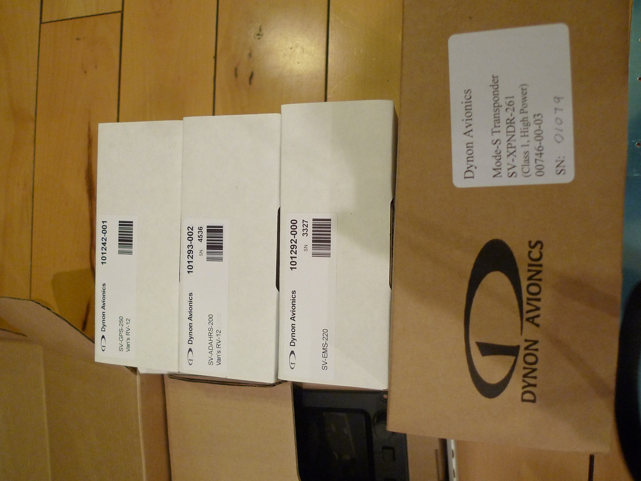
Check the serial # of you unit for a possible issue with noise in the intercom. Details here:
http://www.dynonavionics.com/docs/support_bulletin_030512.html

Note: You may be thinking that you can download engine and flight data from the Skyview onto your USB drive after a flight. CURRENTLY NOT SO!!!
They say "As of SkyView firmware v3.2, the only recording capability in SkyView is an internal log file for Dynon Avionics Engineering use. However, SkyView can stream both flight and engine data from a serial port, and that data can be recorded with an external unit - either a laptop computer or a dedicated data logging device (Google for "data logger"). Data logging is a capability that will be added in a future (but near-term) update of SkyView firmware." 3.3 did not add this capability.
 
They may be catching up in their shipments

I received my Skyview kit yesterday--I was one of the special folks that had already purchased the engine kit--which arrived around the first of December last year. So I must be one of the last of the special folks, and everyone else that hasn't bought their engine kit is next in line....I feel so special...just have to figure out which of the Destruction sections apply to my vintage of fuse/finish kit....
 
What leads you to think this is so? I am one of the "special folks" that has to wait until everyone else get theirs, ordered over a month ago, no word from Vans yet..

. that
I received my Skyview kit yesterday--I was one of the special folks that had already purchased the engine kit--which arrived around the first of December last year. So I must be one of the last of the special folks, and everyone else that hasn't bought their engine kit is next in line....I feel so special...just have to figure out which of the Destruction sections apply to my vintage of fuse/finish kit....
 
My Skyview will likely be next week!

Vans has all the money for my Skyview but not all the parts to send. I received an email on Monday confirming my stuff was ready for shippment except Vans was waiting for a shippment from Dynon with more Skyviews. Their plan was receive the Skyviews on Thursday (8th) and ship on Friday. If the delievery is delayed it would ship till next week at the earliest.

This is the news I received early this week. Actually it has been helpful to read on the posts on other experience so I know better what to expect and it also has given Vans some more time to iron out issues with parts. I hope :rolleyes:
 
Back
Top