What's new
Van's Air Force

Don't miss anything! Register now for full access to the definitive RV support community.

Cowl and intake mod

Mike S

Senior Curmudgeon
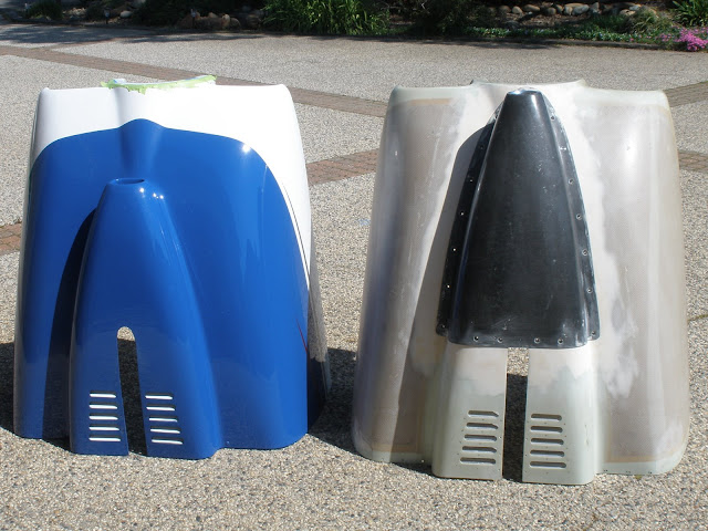
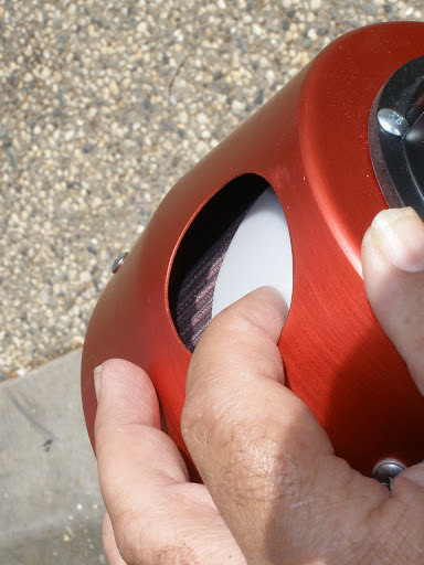
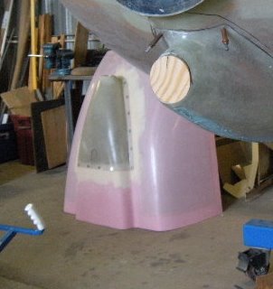
So, what do you do if there is a BIG hole in your lower cowl???

RV-10%20horizontal%20cowl%20mod%20007.jpg


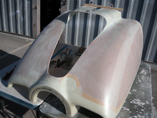
How about covering it up with something like this???

RV-10%20horizontal%20cowl%20mod%20012.jpg


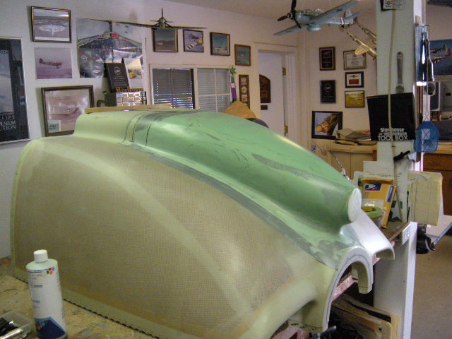
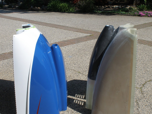
Now, you are probably wondering why would I want to cut up a perfectly good cowl, and add a new hunk of plastic to it??

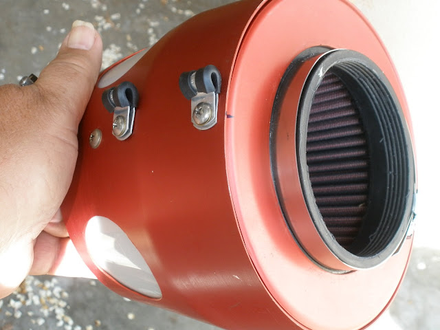
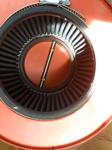
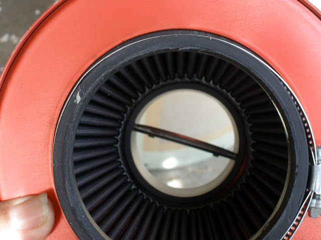
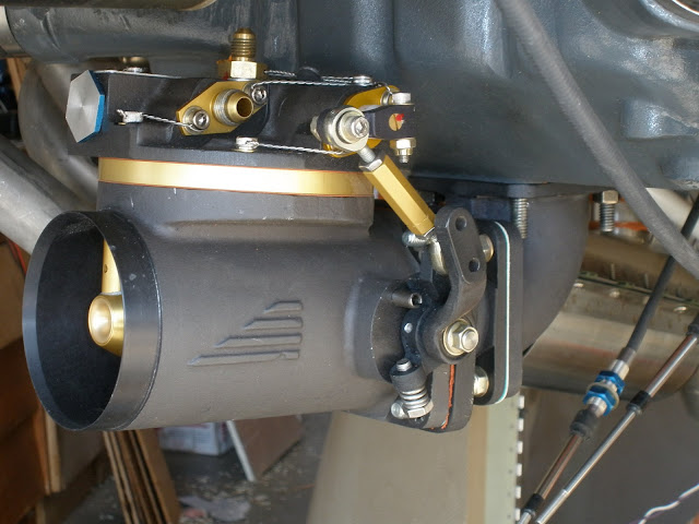
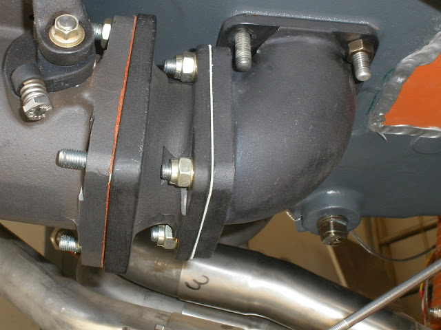
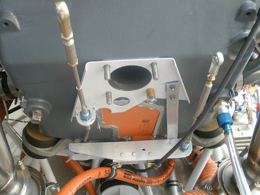
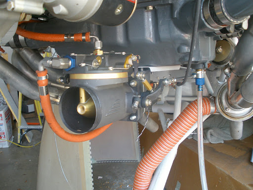
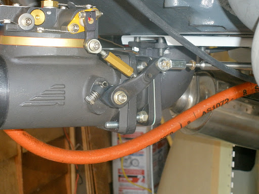
Maybe, just maybe, it is to accommodate something like this???

RV10%20cast%20elbow%20002.jpg


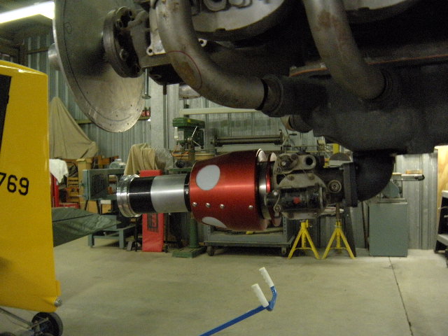
O.K., not exactly like the above, but so close most folks might not see the difference, and besides, I dont have a shot of the finished unit yet.

What does it all mean???

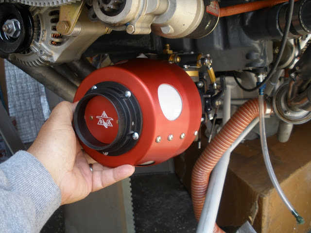
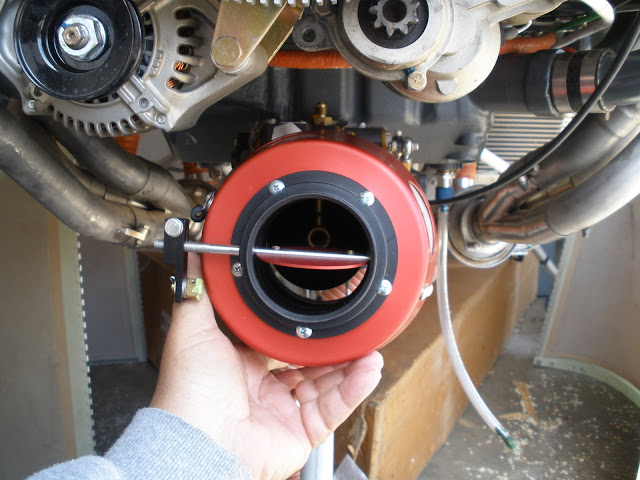
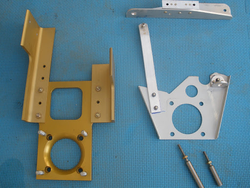
Rod Bower, the ram air guy, is working up a package for the RV 10.

If interested, contact Rod for details.
 
Last edited:
Looks nice Mike. As it happens, I'm doing something similar on my -8, so I've thought about the "big hole" (which is not as big as yours).

There is going to be some loss of structural integrity to the bottom cowl. If we don't so something about it, I suspect we'll see spider cracks or worse at the corners of the opening. To toughen up the edge of the hole I've raked out the first 1/2" of honeycomb core and replaced it with flox/epoxy. Next I'll add two plies of 9 oz on both the inner and outer surfaces, a doubler ring of sorts around the opening. Because the lower cowl can see some significant radiated heat, those plies will be laminated using Aeropoxy PR2032 rather than West 105, just to get the higher Tg (195F vs 125F).
 
Looks nice Mike.

Yes, I agree with you, but Rod is the one who gets the thanks, he is doing the work shown here.

As it happens, I'm doing something similar on my -8

Have you seen what Rod did on his 8??

ROD_6.jpg


There is going to be some loss of structural integrity to the bottom cowl.

Yes, and because of the training wheel on the 10, that big slot for the gear makes it worse. I am going to bend up a piece of .060" or so alum, couple inches wide, bent into a horseshoe shape, with outward facing feet, that will be bolted to the cowl over the slot. Similar to a fork brace on a motorcycle.
 
Ya know, I made an assumption that's probably not correct.....is the new scoop bonded in place or removable? If bonded on place, forget what I said.

Mine is getting an intake scoop much like Rod's, but it will go on and off with a few quarter-turns. Should make cowl installation easy, in particular since I'll have no need to remove it to do a TB adjustment or look inside the lower plenum area.
 
Last edited:
Ya know, I made an assumption that's probably not correct.....is the new scoop bonded in place or removable?

I am going with removable, held on by 18 of these.

4000SetUpCsmall_small1.jpg


With a 3 blade prop, getting the bottom cowl off is a bit of a pain.

Having a big opening will make minor service work easy-----at least that is the plan.
 
My Removable Intake

While only on a lowly carbureted engine....the idea and result is the same. Ease of service. The ability to change the oil and check out the entire underside of the engine without without removing the lower cowl.

my.php
[/URL][/IMG]

my.php
[/URL][/IMG]

my.php
[/URL][/IMG]

I buried and used epoxy & flox on #8 nutplates in the cowl. I use stainless countersunk washers and screws. I like them better than Camlocks....
There is also a strip of carbonfiber about 2" wide at the back of removable intake part and also on the back edges of the lower cowl just for extra stiffness.
 
Looks nice Mike. As it happens, I'm doing something similar on my -8, so I've thought about the "big hole" (which is not as big as yours).

There is going to be some loss of structural integrity to the bottom cowl. If we don't so something about it, I suspect we'll see spider cracks or worse at the corners of the opening. To toughen up the edge of the hole I've raked out the first 1/2" of honeycomb core and replaced it with flox/epoxy. Next I'll add two plies of 9 oz on both the inner and outer surfaces, a doubler ring of sorts around the opening. Because the lower cowl can see some significant radiated heat, those plies will be laminated using Aeropoxy PR2032 rather than West 105, just to get the higher Tg (195F vs 125F).

Dan, planning on using the quick release fastiners for eaze of install/removal. Once the quick release locations are established, I will cleco on the scoop (with mold release) and lay up an inner flange (2") attached to the original cowl and mold release on the new scoop creating a right angle stiffiner (.5")for structional support. Using carbon layup of 2.5" wide (2" x .5"vertical lip) following the contour of the new scoop, the .5" angle should really stiffen it up. The cross section just ahead of the cut for the nose gear will be supported with an .040" alluminum flange attached cross ways to the glass creating a support for the quick fastiners riveted thru the glass and the aluminum.
I also dug out the honeycomb and squeegied in flox and sanded to a round edge. Using the aeropoxy is a good idea. Where can I get some? The 2" flange will also provide a nice bed for the quick fastiners.
Rod
 
Sounds like a good plan Rod. If I picture your description correctly, the outer surface of the scoop winds up flush with the surface of the cowl, which is a nice trick.

Looks like a floating receptacle in Mike's post. Bill has a point about using screws and nutplates. Don't want the scoop moving around and chaffing, and a row of screws returns the scoop to structural duty, more or less. Gonna think about that. My scoop hole isn't nearly as big as Bill's or yours, so I may stick with quarter-turns and use fixed receptacles.

Wicks has the PR2032 Aeropoxy, just ordered more yesterday.

BTW, nice shop. Is that an L-4 photo on the wall?
 
Wow, you guys are doing some really cool stuff there. I think I just got my morning VAF education :).
 
Just as a data point, the F1 Rocket cowls have a removeable scoop on the bottom of the cowl, similiar to the ones here. No special bracing is used, it's just screwed down to a flange using #8 countersunk screws about 3" apart. I've never heard of any problems in this area from any of the Rockets flying.
 
Just as a data point, the F1 Rocket cowls have a removeable scoop on the bottom of the cowl, similiar to the ones here. No special bracing is used, it's just screwed down to a flange using #8 countersunk screws about 3" apart. I've never heard of any problems in this area from any of the Rockets flying.

Good point Randy. I think the difference is the Rocket cowls are solid laminate all around the opening, yes? We're cutting a hole in a honeycomb core area with very thin face plies.
 
We're cutting a hole in a honeycomb core area with very thin face plies.

Dan, re read post 8, Rod is reinforcing the opening with carbon, a right angle lip, and digging out the honeycomb and inserting flox.

Should be way strong.

Thanks for the heads up, however, I think (hope?) Rod has it under control.
 
Sounds like a good plan Rod. If I picture your description correctly, the outer surface of the scoop winds up flush with the surface of the cowl, which is a nice trick.

Looks like a floating receptacle in Mike's post. Bill has a point about using screws and nutplates. Don't want the scoop moving around and chaffing, and a row of screws returns the scoop to structural duty, more or less. Gonna think about that. My scoop hole isn't nearly as big as Bill's or yours, so I may stick with quarter-turns and use fixed receptacles.

Wicks has the PR2032 Aeropoxy, just ordered more yesterday.

BTW, nice shop. Is that an L-4 photo on the wall?

The L4 is a Wag Aero replica and lives next to me. I was in partinership for 4 years and loved the low and slow morning flights. We are just getting into the POPPI bloom in the foothills and its brilliant.

Mike's cowl will use the 1/4 turn Quick release fastiners. I think that the #8 nut plates are stronger but the Quick release really holds quite well. The scoop is nested and allows very little wiggle room. (which just might prevent the crazing issue). I suspect that if consideration is given to large radiius and clearance gaps that are not too tight, combined with the preventive measures talked about earlier should do the job.

With regard to the #8 stainless washers in one of the pictures:
Try using a #6 washer dimled for the #8. Looks much cleaner!!
Rod
 
Is that an automatic mixture control that I see on the servo?

Bob, the fuel servo seen in this photo is actually a RSA-5 bendix. Mike's will have an Air Flow Performance FM-200. The air flow meter actually has better flow properties than the RSA-5.
Rod
 
<<The L4 is a Wag Aero replica and lives next to me. I was in partnership for 4 years and loved the low and slow morning flights.>>

Right on brother. Had a '45 J-model for 300 hours....a down-low dawn patrol with the sun rising over the mist is as good as it gets.

Off-topic, but you might like a quick story....a friend managed to find the military aircraft record card in the archives at Maxwell. The card had a dated entry for everything from contract award onward. It came off the assembly line in Lock Haven a few days after VJ Day, was accepted shortly after, and was picked up by a ferry pilot who was to deliver it to Fort Bragg. The next card entry was dated two weeks later; "Aircraft Overdue". The following entry was dated the next day, and simply said "Aircraft Arrived".

Ok, you're a young ferry pilot. The war is over, nobody much cares about details......and you have a brand new cow-pasture airplane. Hmmm.

Maybe it was the worst weather week in history, and maybe it did take two weeks to get from central PA to North Carolina. However, I always wished that airplane could talk, and I suspect the ferry pilot was glad it could not <g>
 
<<Dan, re read post 8, Rod is reinforcing the opening with carbon, a right angle lip, and digging out the honeycomb and inserting flox.>>

Right, and per post #10, I think he is doing a great job. Ain't worried about Rod; he's a builder.
 
Bob, the fuel servo seen in this photo is actually a RSA-5 bendix. Mike's will have an Air Flow Performance FM-200. The air flow meter actually has better flow properties than the RSA-5.
Rod

Sure, but I see an automatic mixture control bellows on the side of the RSA-5, and I've never seen one on a -5 but I've got a RSA-10 that has one. Just curious.
 
Sure, but I see an automatic mixture control bellows on the side of the RSA-5, and I've never seen one on a -5 but I've got a RSA-10 that has one. Just curious.

Rocket Bob, you have the greatest Photo of the bunch.. Sort of remindes me of John Bellosi of good times past. The RSA 5 is a loaner so disregard the
the photo. Rod
 
It's a combo RAM,Filtered,Alternate air

The red canister is a unit designed by Rob Bower that serves a combination of purposes.
1. It has a butterfly valve on the intake to allow for RAM air direct into the fuel servo. (increased MP, a mini turbo)
2. With the butterfly shut it acts as an air filter (There is a K&N filter contained within the housing).
3. The plastic discs on the side of the canister open and allow for warm (alternate) cowl air to the servo. Alternate Air

A 3 in 1 solution with performance benefits!
 
Update Photos------I hope...........

Well, I have had the cowl back for a while, finally got around to getting a couple of shots to show the difference from a stock cowl.

P3300019.jpg


P3300020.jpg
 
Great thread! Thanks for taking the time to post!

Tom, thanks for the kind words.

As of now, I am working on getting all the ancillary stuff -----fuel lines, throttle and mixture controls----to function with the change in fuel servo location.

One problem, the direction of travel for the mixture shaft/arm must be reversed.

Luckily, Don at Airflow Performance says to just send him the unit, he will take care of this at no charge.

Can you say GREAT CUSTOMER SERVICE???:D

All in all, I am quite pleased with the project so far, and I really like the access to the bottom of the engine with the scoop off (bottom cowl still on).

Much thanks again to Don, and Rod Bower.
 
Mike

are the louvers on the lower cowl standard RV-10 ware or a mod? I assume they are for increased air flow and engine cooling - is this a common issue on the -10 or is this in response to an anticipated need with the engine being used?

just curious

erich
 
Erich, they are standard kit units.

Some folks are adding more, but my buddy's plane (painted cowl) has been just fine, now two years in the air.
 
A little detail

Never having built a plane and done anything but fly them, what is that? :D

As was stated prior, this is Rod Bowers ram air setup.

It contains a K&N air filter, seen here from the inside.

P3310005.jpg


The two Adel clamps are used to hold the bowden cable that controls the inlet valve.

Here is the valve closed, from outside,

P3310008.jpg


And inside.

P3310006.jpg


And here is it open, again from the outside, and a view from inside the servo unit.

P3310009.jpg


P3310007.jpg


Lastly, this is how the air gets into the unit when the ram air control is closed. These are basically like reed valves in an air compressor, or a two stroke engine.

P3310012.jpg


Hope this helps make sense of things.

More to follow-----
 
Last edited:
A bit more.

To continue, the fuel servo has been re-mounted in a horizontal manner.

I believe this is the way Rockets do it--------

To make it all work, you need an elbow, and an adapter to match the throat diameter to the intake hole in the sump.

P3310002.jpg


P3310003.jpg


By the way, that adapter is canted up 5*, your eyes are not fooling you:D

These are standard parts from Airflow Performance.

Thanks for lookin'
 
Michael, welcome.

Deems is the guy that created the new scoop and gave it to Rod to duplicate.

Michael

Hey there, welcome to VAF. Good to have you aboard.

Yes, even though I only dealt with Rod, he did mention Deems's was part of the mix.

Deems had a slightly different setup, here is a shot of his scoop-----pepto cowl, in background.

RV-10%20horizontal%20cowl%20mod%20001.jpg


IIRC, what Rod told me, Deems used the fuel servo updraft, and put an elbow on the intake side of it, thus the inlet is lower, and back farther.

But, I agree, sure does look like Deems is the driving force to the design
 
Last edited:
Project update

Well, I guess it is time to show some progress on this mod.

Here is the original servo/cable mounting part from AirFlow Perf on the left, and the new parts I had to make----(or modify) to attach the throttle and mixture cables. I also included provisions to mount a couple of adel clamps for fuel hose, and prop cable. Also shown are the cable extensions I had to order.

P6120006%20%282%29.jpg


The new parts installed on the engine.

P6120010%20%282%29.jpg


All the stuff on the engine, for a final fitting/mock up. New fuel lines were needed to fit relocated unit.

P6120011%20%282%29.jpg


Here you can see the apx 5" that the fuel servo moved forward. This is in addition to a 180 rotation, which moved the mixture/throttle arms to the opposite sides. Also, a good shot of the extensions in place.

P6120012%20%282%29.jpg


Now for a final looksee by my local tech consular, disassemble/reassemble with gaskets and correct hardware.

So, was it worth it???

No way to tell, as I have no baseline to compare against.

Would I do it again??

Yes, especially after reading Deems Davis's comments about the Bowers system, in his "first flight" notice on the mothership.
 
Last edited:
Back
Top